SlideShare ist ein Scribd-Unternehmen logo
1 von 9
Downloaden Sie, um offline zu lesen
.
.
.
.
.                                                                            DATE    August 2004
.                                                                            PAGE    1/9

TIE-28: Bubbles and Inclusions in Optical Glass

0. Introduction
Optical glass in general is nearly free of bubbles and inclusions compared to other technical
glasses due to sophisticated production processes, which are optimized for low bubble
content. Nevertheless to specify an optical glass for a desired optical component it is helpful
to know the background on the generation of bubbles and inclusions and their impact on the
application. This technical information gives an overview on the topics involved in the
selection of the right specification for bubbles and inclusions.

1. Generation of Bubbles in Optical Glass:
The compositions of glasses are frequently given in form of oxides. In reality however raw
materials used for melting may be carbonates or hydrogen-carbonates and others. Melting of
such raw materials produces reactions gases forming bubbles in the melt.

These bubbles will be removed with the refining process, which is part of all glass melting.
During the refining process the glass temperature is increased. The solubility of the gas
components decreases. Bubbles will be formed and grow much more rapidly. The elevated
temperature decreases the viscosity of the glass supporting the bubbles to move up and
vanish from the melt.

Residual fine bubbles, which do not succeed to leave the melt will be removed by chemical
reactions caused by refining agents. These are elements, which change their valency during
cooling down. When such an element searches for a chemical binding partner, it will take the
gas of the tiny bubbles and dissolve it back into the glass. The gas atoms still will be present
in the glass but not disturbing anymore.

Residual bubbles in optical glass may come from different sources. In most cases they come
from non-perfect refining.


Fig. 1: Optical glass block with a small amount of bubbles


TIE-28: Bubbles and Inclusions in Optical Glass
.
.
.
.
.                                                                        DATE    August 2004
.                                                                        PAGE    2/9

Nevertheless a certain amount of gaseous bubbles within the glass melt during the melting
process is essential to achieve a good homogenization of the melt. Ascending bubbles lead
to an additional convection movement of the glass melt and therefore improve the
homogenization process. Fig. 1 shows an N-BK7 glass sample with only a small amount of
bubbles.

The generation of bubbles by the melting and casting process is not the only possible
process. Sometimes bubbles can also be generated in hot forming processes. Figure 2
shows bubble fogs generated by reheat pressing of N-BK7, where the preform was
damaged. Tiny bubbles were captured in a small flaw. Note: The length of the pattern in the
picture is smaller than 2 mm.


Fig. 2: Bubbles generated by reheat pressing of N-BK7.


2. Generation of Inclusions in Optical Glass:
Inclusions (solid particles) within the glass can be generated due to:
    Ø Remains from the batch that have not been melted completely
    Ø Wall material with low solubility
    Ø Particles from the outer surrounding
    Ø Platinum particles from the tank tools
    Ø Devitrification processes, crystallization

In general solids are gross contaminants that should be avoided if possible. Nevertheless
sometimes such contaminations cannot be avoided in total due to the overall melting
process. For example platinum particles can be often found in optical glasses due to the
frequent use of platinum as wall material in the standard melting tank. Nevertheless such
platinum particles are rather small (< 0.03 mm in general) and therefore do not exhibit
problems in standard applications whereas they may become important in high energy laser
applications.


TIE-28: Bubbles and Inclusions in Optical Glass
.
.
.
.
.                                                                            DATE    August 2004
.                                                                            PAGE    3/9


The prevention of devitrification processes limits some glasses to special production
procedures and formats. Certain glasses show a high risk of devitrification in special
temperature regions and can therefore only produced in special sizes. Figure 3 shows crystal
in N-SF6 that was generated due to devitrification.


Fig. 3: N-SF6 with crystal due to devitrification


3. The Influence of Bubbles and Inclusions on Optical Application
In theory every part of a lens has the same imaging properties (if one may neglect image
aberrations). For example covering a lens completely with only letting the light pass through
a tiny spot in the upper corner one can still see the complete image but with less intensity. In
figure 4 a) very simplified part of an optical system is displayed. This optical system consists
of two lenses. The first lens is positioned at an intermediate image plane with the image of an
arrow. The second lens images the arrow to the final image plane. Additionally four light rays
are constructed. It can be seen clearly that independent from another the two upper rays and
the two lower rays both image the tip of the arrow correctly. The position of the first lens in
this optical system is an image plane. The position of the second lens is a pupil.

In figure 4 b) the influence of bubbles and inclusions that are located in lenses near the
pupils of an optical system can be seen. They do not disturb the shape of the final image but
they reduce the image contrast and intensity because part of the light is scattered. The size
of this effect depends on the amount of bubbles and inclusions per area of the glass.


TIE-28: Bubbles and Inclusions in Optical Glass
.
.
.
.
.                                                                                         DATE     August 2004
.                                                                                         PAGE     4/9


Bubbles and inclusions located in optical elements near the image plane can be harmful,
because they might be visible in the final image (depending e.g. on inclusion size and image
detector pixel size and sensitivity). This is displayed in figure 4 c). The inclusion within the
first lens can be seen in the final image.

In reality lens systems consist of many different lenses and are much more complicated than
the displayed example. Therefore the designer has to take into account individually the
possible bubbles and inclusions in the optical system for any lens.

                                       image
                                       plane                   pupil


                                                  light rays


                                                                                 final
                        intermediate                                            image
                            image
                                                       focal
                                                      length
              = inclusion

                                  a)               lenses


         b) inclusion on pupil plane ->                                 c) inclusion on image plane ->
       reduced brightness and contrast                                 image of inclusion in final image


Fig. 4: The influence of bubbles and inclusions in a simplified optical system

With pulsed lasers, especially in the focus of the beam, light output of giga watt and power
densities far above 109 Watt/cm 2 can be achieved. Under the effect of such high energy and
power densities of electromagnetic waves, internal and surface damage can occur in optical
glasses. One reason for the damage are microscopically small extraneous particles in the
glass. Platinum particles in the glass are of special importance. The damage threshold for
platinum particles extends from energy densities of 2.5 to 8 J/cm2. The resulting damage site
can grow by continued irradiation to size larger than 1 mm [3]


TIE-28: Bubbles and Inclusions in Optical Glass
.
.
.
.
.                                                                            DATE   August 2004
.                                                                            PAGE   5/9

4. Inspection of bubbles and inclusions
The inclusion quality will be assessed by visual inspection. To visualize the bubbles and
inclusions the following measurement setup is used in general (figure 5). The glass is placed
on a black background and illuminated from the side. The glass is viewed from above by
looking through it toward the black background. The bubbles and inclusions become visible
as bright spots. This arrangement is very sensitive for the quantification of bubbles and
inclusions. To determine the sizes either comparison standards or microscopes are used.
The evaluation includes all bubbles and inclusions with dimensions ≥ 0.03 mm. Figure 6
shows a typical view using this measurement setup.


                                                            Inspector


                                                         Inclusion      Glass specimen

            Halogen Lamp,
             narrow beam
                                                  Black screen


Fig. 5: Schematic measurement setup for inclusion inspection down to 0.03 mm diameter.


Fig. 6: View of inspected glass sample


TIE-28: Bubbles and Inclusions in Optical Glass
.
.
.
.
.                                                                                 DATE   August 2004
.                                                                                 PAGE   6/9

5. Specification
5.1 Bubbles and Inclusions
The characterization of bubble content of a glass is performed by reporting the total cross
section in mm 2 of a 100 cm 3 glass volume, calculated as the sum of the detected cross
sections of bubbles. Additionally the maximum allowable number per 100 cm 3 and the size
dependent diameter of bubbles is defined for each cross section. Inclusions in glass, such as
stones or crystals are treated as bubbles of equivalent cross section.

The bubbles classes and the maximum allowable quantities and diameters of bubbles and
inclusions in optical glass are listed in table 1. If the inclusion cross section is not spherical,
the diameter shall be the mean of the largest and the smallest distance across the field of
view.

Bubbles class according         B0                               B1
to catalog data sheet of
the concerned glass type
Quality step                                  VB     EVB                     VB          EVB
Maximum         allowable       0.03          0.01   0.006       0.1         0.03        0.02
cross section of all
bubbles and inclusions
in mm2 per 100 cm 3 of
glass volume
maximum         allowable       10            4      2           30          10          4
quantity per 100 cm3
Maximum        50               0.1           0.10   0.10        0.15        0.15        0.10
allowable      100              0.15          0.15   0.10        0.20        0.15        0.10
diameter of 200                 0.20          0.15   0.10        0.30        0.20        0.10
bubbles or 300                  0.25          0.20   -           0.40        0.25        -
inclusions in 500               0.40          -      -           0.60        -           -
mm             800              0.55          -      -           0.80        -           -

Tab. 1: Tolerances for bubbles and inclusions in optical glass.

The increased quality steps VB (increased bubble selection) and EVB (extra increased
bubble selection) are only applicable for fabricated pieces of glass and pressings but not for
raw glass. Therefore the manufacturer can choose a glass with areas of lower bubble quality
unless there are other suitable sized parts that fulfill the bubbles specification of the
customer.

The customer should always indicate if the bubble and inclusion specification is only valid for
the fabricated piece of glass or for the raw piece. For example if a raw glass does not fulfil
the specification in total, parts of it might be within specification and can be used for the
application if for example a bigger amount of only small lenses are fabricated from the raw
glass.

From strips and blocks normally much smaller finished parts are produced. Here occasional,
individual bubbles having greater dimensions are permitted, if the limit values for the total
cross section area and quantity per volume are maintained.


TIE-28: Bubbles and Inclusions in Optical Glass
.
.
.
.
.                                                                           DATE   August 2004
.                                                                           PAGE    7/9

Bubbles may be distributed. Instead of a single bubble with limit size, a larger number of
bubbles of lesser dimensions is allowable (refer to [1],[2]).


5.2 Concentrations
Concentrations of bubbles and inclusions in the later final part are not allowed. A
concentration occurs when there are multiple inclusions and more than 20% of the total
number of inclusions occurs in any 4% of the sample. However, when the total number of
inclusions found in the sample is ten or less, there must be two or more inclusions falling
within a 4% area to constitute a concentration.


5.3 Haze
Haze refers to inclusions within the glass with sizes < 0.01 mm and much smaller.
They originate from phase separation or devitrification, i.e. small droplets or crystals with
different refractive index than the surrounding glass matrix. Note that in figure 7 haze
corresponds to the small structures.


Fig. 7: View of a sample with haze through an electron microscope (tiny dots between larger
crystals in a bad quality glass sample).


5.3.1 Inspection of haze
The arrangement for the inspection of haze is similar to the inspection of bubbles and
inclusions. The difference is the direction of the illumination. The glass piece under
inspection will be illuminated almost in the direction of vision in front of a black screen in
comparison to the normal bubble and inclusion inspection where the glass is illuminated
almost perpendicular to the viewing direction (see figure 8). The inspector assesses the
intensity of the scattered light. This is a very sensitive arrangement revealing even slight
haze levels.


TIE-28: Bubbles and Inclusions in Optical Glass
.
.
.
.
.                                                                            DATE    August 2004
.                                                                            PAGE    8/9


Fig. 8: Experimental setup for haze inspection


5.4 Quality Grade „extra low platinum particle content“ (EP)
Gas bubbles and crystals are nearly irrelevant for the damage mechanism of the glass during
laser irradiation. On the contrary very small amounts of microscopic platinum particles can
lead to local damages in the glass. Therefore the bubble classes do not cover the necessary
specification of platinum particles for glass with low platinum content.

To specify glass with extra low platinum content it is important to add the expression “extra
low platinum particle content” (EP) to the desired bubble class. In this case platinum particles
are examined independent from the usual bubble classification. The registration limit for
platinum particles is ≥ 0.003 mm; smaller particles are not visible in general.

The quality grade „extra low platinum particle content” (EP) is characterised by:

    max. amount of platinum particles in 100 cm3
                          ≥ 0.05 mm                               0
                          ≥ 0.03 mm up to < 0.05 mm               5
                          ≥ 0.003 mm up to < 0.03 mm              12

Table 3: Specification of platinum particles


TIE-28: Bubbles and Inclusions in Optical Glass
.
.
.
.
.                                                                            DATE   August 2004
.                                                                            PAGE   9/9

5.3.1 Inspection of platinum particle content
The samples need to be polished on 4 surfaces. For inspection a strong lamp with a
collimated beam of parallel light with small beam cross-section is used. The light is scattered
by the platinum particles and therefore the platinum particles appear to be small bright spots.
Standard accuracy for testing bubbles and inclusion size is 0.03 mm. Dimensions of smaller
particles cannot be measured.

Smaller particles are counted qualitatively. On special demand size and amount of platinum
particles can be characterised using high-resolution microscopy. The expense of such kind of
measurement is significantly higher.


6. Literature

[1] ISO/DIS 10110 - part 3; Preparation of drawings for optical elements and systems;
Material Imperfections – Bubbles and Inclusions; 1996

[2] ISO 12123 – Raw optical glass in bulk and preshaped forms – Bubbles and inclusions –
Test method and classification; 1996

[3] SCHOTT Technical Information Nr. 21, 4/1988


For more information please contact:
Optics for Devices
SCHOTT AG
Germany
Phone: + 49 (0)6131/66-3835
Fax: + 49 (0)6131/66-1998
E-mail: info.optics@schott.com
www.schott.com/optics_devices


TIE-28: Bubbles and Inclusions in Optical Glass

Weitere ähnliche Inhalte

Mehr von SCHOTT

Effect of Detergent Concentration and Type when printing on Epoxy Coated NEXT...
Effect of Detergent Concentration and Type when printing on Epoxy Coated NEXT...Effect of Detergent Concentration and Type when printing on Epoxy Coated NEXT...
Effect of Detergent Concentration and Type when printing on Epoxy Coated NEXT...SCHOTT
 
Microarray Solutions newsletter #5
Microarray Solutions newsletter #5Microarray Solutions newsletter #5
Microarray Solutions newsletter #5SCHOTT
 
SCHOTT Glass Substrates for Microfluidic Applications
SCHOTT Glass Substrates for Microfluidic ApplicationsSCHOTT Glass Substrates for Microfluidic Applications
SCHOTT Glass Substrates for Microfluidic ApplicationsSCHOTT
 
SCHOTT NEXTERION® HiSens optical coating for high sensitive microarray analysis
SCHOTT NEXTERION® HiSens optical coating for high sensitive microarray analysisSCHOTT NEXTERION® HiSens optical coating for high sensitive microarray analysis
SCHOTT NEXTERION® HiSens optical coating for high sensitive microarray analysisSCHOTT
 
NEXTERION® Slide P - The slide of choice for Antibody Microarrays
NEXTERION® Slide P - The slide of choice for Antibody MicroarraysNEXTERION® Slide P - The slide of choice for Antibody Microarrays
NEXTERION® Slide P - The slide of choice for Antibody MicroarraysSCHOTT
 
Protein Microarrays: Approaches to Printing
Protein Microarrays: Approaches to PrintingProtein Microarrays: Approaches to Printing
Protein Microarrays: Approaches to PrintingSCHOTT
 
NEXTERION® Microarray slides with barcodes and custom logos from SCHOTT
NEXTERION® Microarray slides with barcodes and custom logos from SCHOTTNEXTERION® Microarray slides with barcodes and custom logos from SCHOTT
NEXTERION® Microarray slides with barcodes and custom logos from SCHOTTSCHOTT
 
Compatibility of DMSO spotting buffers with Nexterion Slide E Epoxy-coated Mi...
Compatibility of DMSO spotting buffers with Nexterion Slide E Epoxy-coated Mi...Compatibility of DMSO spotting buffers with Nexterion Slide E Epoxy-coated Mi...
Compatibility of DMSO spotting buffers with Nexterion Slide E Epoxy-coated Mi...SCHOTT
 
Modification to the Nexterion Spot Spotting buffer composition
Modification to the Nexterion Spot Spotting buffer compositionModification to the Nexterion Spot Spotting buffer composition
Modification to the Nexterion Spot Spotting buffer compositionSCHOTT
 
Protocol for Preparation of Streptavidin-coated Slides based on SCHOTT Nexter...
Protocol for Preparation of Streptavidin-coated Slides based on SCHOTT Nexter...Protocol for Preparation of Streptavidin-coated Slides based on SCHOTT Nexter...
Protocol for Preparation of Streptavidin-coated Slides based on SCHOTT Nexter...SCHOTT
 
Publications citing schott_nexterion_microarray_products_20100929
Publications citing schott_nexterion_microarray_products_20100929Publications citing schott_nexterion_microarray_products_20100929
Publications citing schott_nexterion_microarray_products_20100929SCHOTT
 
Overview of SCHOTT’s protein micro-array slide surfaces
Overview of SCHOTT’s protein micro-array slide surfacesOverview of SCHOTT’s protein micro-array slide surfaces
Overview of SCHOTT’s protein micro-array slide surfacesSCHOTT
 
SCHOTT Nexterion Slide H poster presented at PepTalk 2004
SCHOTT Nexterion Slide H poster presented at PepTalk 2004SCHOTT Nexterion Slide H poster presented at PepTalk 2004
SCHOTT Nexterion Slide H poster presented at PepTalk 2004SCHOTT
 
SCHOTT Nexterion Micro-array Glass Substrates Presentation
SCHOTT Nexterion Micro-array Glass Substrates PresentationSCHOTT Nexterion Micro-array Glass Substrates Presentation
SCHOTT Nexterion Micro-array Glass Substrates PresentationSCHOTT
 
SCHOTT Nexterion® Glass B surface flatness
SCHOTT Nexterion® Glass B surface flatnessSCHOTT Nexterion® Glass B surface flatness
SCHOTT Nexterion® Glass B surface flatnessSCHOTT
 

Mehr von SCHOTT (15)

Effect of Detergent Concentration and Type when printing on Epoxy Coated NEXT...
Effect of Detergent Concentration and Type when printing on Epoxy Coated NEXT...Effect of Detergent Concentration and Type when printing on Epoxy Coated NEXT...
Effect of Detergent Concentration and Type when printing on Epoxy Coated NEXT...
 
Microarray Solutions newsletter #5
Microarray Solutions newsletter #5Microarray Solutions newsletter #5
Microarray Solutions newsletter #5
 
SCHOTT Glass Substrates for Microfluidic Applications
SCHOTT Glass Substrates for Microfluidic ApplicationsSCHOTT Glass Substrates for Microfluidic Applications
SCHOTT Glass Substrates for Microfluidic Applications
 
SCHOTT NEXTERION® HiSens optical coating for high sensitive microarray analysis
SCHOTT NEXTERION® HiSens optical coating for high sensitive microarray analysisSCHOTT NEXTERION® HiSens optical coating for high sensitive microarray analysis
SCHOTT NEXTERION® HiSens optical coating for high sensitive microarray analysis
 
NEXTERION® Slide P - The slide of choice for Antibody Microarrays
NEXTERION® Slide P - The slide of choice for Antibody MicroarraysNEXTERION® Slide P - The slide of choice for Antibody Microarrays
NEXTERION® Slide P - The slide of choice for Antibody Microarrays
 
Protein Microarrays: Approaches to Printing
Protein Microarrays: Approaches to PrintingProtein Microarrays: Approaches to Printing
Protein Microarrays: Approaches to Printing
 
NEXTERION® Microarray slides with barcodes and custom logos from SCHOTT
NEXTERION® Microarray slides with barcodes and custom logos from SCHOTTNEXTERION® Microarray slides with barcodes and custom logos from SCHOTT
NEXTERION® Microarray slides with barcodes and custom logos from SCHOTT
 
Compatibility of DMSO spotting buffers with Nexterion Slide E Epoxy-coated Mi...
Compatibility of DMSO spotting buffers with Nexterion Slide E Epoxy-coated Mi...Compatibility of DMSO spotting buffers with Nexterion Slide E Epoxy-coated Mi...
Compatibility of DMSO spotting buffers with Nexterion Slide E Epoxy-coated Mi...
 
Modification to the Nexterion Spot Spotting buffer composition
Modification to the Nexterion Spot Spotting buffer compositionModification to the Nexterion Spot Spotting buffer composition
Modification to the Nexterion Spot Spotting buffer composition
 
Protocol for Preparation of Streptavidin-coated Slides based on SCHOTT Nexter...
Protocol for Preparation of Streptavidin-coated Slides based on SCHOTT Nexter...Protocol for Preparation of Streptavidin-coated Slides based on SCHOTT Nexter...
Protocol for Preparation of Streptavidin-coated Slides based on SCHOTT Nexter...
 
Publications citing schott_nexterion_microarray_products_20100929
Publications citing schott_nexterion_microarray_products_20100929Publications citing schott_nexterion_microarray_products_20100929
Publications citing schott_nexterion_microarray_products_20100929
 
Overview of SCHOTT’s protein micro-array slide surfaces
Overview of SCHOTT’s protein micro-array slide surfacesOverview of SCHOTT’s protein micro-array slide surfaces
Overview of SCHOTT’s protein micro-array slide surfaces
 
SCHOTT Nexterion Slide H poster presented at PepTalk 2004
SCHOTT Nexterion Slide H poster presented at PepTalk 2004SCHOTT Nexterion Slide H poster presented at PepTalk 2004
SCHOTT Nexterion Slide H poster presented at PepTalk 2004
 
SCHOTT Nexterion Micro-array Glass Substrates Presentation
SCHOTT Nexterion Micro-array Glass Substrates PresentationSCHOTT Nexterion Micro-array Glass Substrates Presentation
SCHOTT Nexterion Micro-array Glass Substrates Presentation
 
SCHOTT Nexterion® Glass B surface flatness
SCHOTT Nexterion® Glass B surface flatnessSCHOTT Nexterion® Glass B surface flatness
SCHOTT Nexterion® Glass B surface flatness
 

SCHOTT Guides: Bubbles and Inclusions in Optical Glass

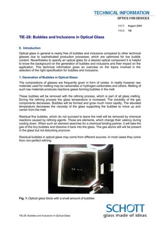
  • 1. . . . . . DATE August 2004 . PAGE 1/9 TIE-28: Bubbles and Inclusions in Optical Glass 0. Introduction Optical glass in general is nearly free of bubbles and inclusions compared to other technical glasses due to sophisticated production processes, which are optimized for low bubble content. Nevertheless to specify an optical glass for a desired optical component it is helpful to know the background on the generation of bubbles and inclusions and their impact on the application. This technical information gives an overview on the topics involved in the selection of the right specification for bubbles and inclusions. 1. Generation of Bubbles in Optical Glass: The compositions of glasses are frequently given in form of oxides. In reality however raw materials used for melting may be carbonates or hydrogen-carbonates and others. Melting of such raw materials produces reactions gases forming bubbles in the melt. These bubbles will be removed with the refining process, which is part of all glass melting. During the refining process the glass temperature is increased. The solubility of the gas components decreases. Bubbles will be formed and grow much more rapidly. The elevated temperature decreases the viscosity of the glass supporting the bubbles to move up and vanish from the melt. Residual fine bubbles, which do not succeed to leave the melt will be removed by chemical reactions caused by refining agents. These are elements, which change their valency during cooling down. When such an element searches for a chemical binding partner, it will take the gas of the tiny bubbles and dissolve it back into the glass. The gas atoms still will be present in the glass but not disturbing anymore. Residual bubbles in optical glass may come from different sources. In most cases they come from non-perfect refining. Fig. 1: Optical glass block with a small amount of bubbles TIE-28: Bubbles and Inclusions in Optical Glass
  • 2. . . . . . DATE August 2004 . PAGE 2/9 Nevertheless a certain amount of gaseous bubbles within the glass melt during the melting process is essential to achieve a good homogenization of the melt. Ascending bubbles lead to an additional convection movement of the glass melt and therefore improve the homogenization process. Fig. 1 shows an N-BK7 glass sample with only a small amount of bubbles. The generation of bubbles by the melting and casting process is not the only possible process. Sometimes bubbles can also be generated in hot forming processes. Figure 2 shows bubble fogs generated by reheat pressing of N-BK7, where the preform was damaged. Tiny bubbles were captured in a small flaw. Note: The length of the pattern in the picture is smaller than 2 mm. Fig. 2: Bubbles generated by reheat pressing of N-BK7. 2. Generation of Inclusions in Optical Glass: Inclusions (solid particles) within the glass can be generated due to: Ø Remains from the batch that have not been melted completely Ø Wall material with low solubility Ø Particles from the outer surrounding Ø Platinum particles from the tank tools Ø Devitrification processes, crystallization In general solids are gross contaminants that should be avoided if possible. Nevertheless sometimes such contaminations cannot be avoided in total due to the overall melting process. For example platinum particles can be often found in optical glasses due to the frequent use of platinum as wall material in the standard melting tank. Nevertheless such platinum particles are rather small (< 0.03 mm in general) and therefore do not exhibit problems in standard applications whereas they may become important in high energy laser applications. TIE-28: Bubbles and Inclusions in Optical Glass
  • 3. . . . . . DATE August 2004 . PAGE 3/9 The prevention of devitrification processes limits some glasses to special production procedures and formats. Certain glasses show a high risk of devitrification in special temperature regions and can therefore only produced in special sizes. Figure 3 shows crystal in N-SF6 that was generated due to devitrification. Fig. 3: N-SF6 with crystal due to devitrification 3. The Influence of Bubbles and Inclusions on Optical Application In theory every part of a lens has the same imaging properties (if one may neglect image aberrations). For example covering a lens completely with only letting the light pass through a tiny spot in the upper corner one can still see the complete image but with less intensity. In figure 4 a) very simplified part of an optical system is displayed. This optical system consists of two lenses. The first lens is positioned at an intermediate image plane with the image of an arrow. The second lens images the arrow to the final image plane. Additionally four light rays are constructed. It can be seen clearly that independent from another the two upper rays and the two lower rays both image the tip of the arrow correctly. The position of the first lens in this optical system is an image plane. The position of the second lens is a pupil. In figure 4 b) the influence of bubbles and inclusions that are located in lenses near the pupils of an optical system can be seen. They do not disturb the shape of the final image but they reduce the image contrast and intensity because part of the light is scattered. The size of this effect depends on the amount of bubbles and inclusions per area of the glass. TIE-28: Bubbles and Inclusions in Optical Glass
  • 4. . . . . . DATE August 2004 . PAGE 4/9 Bubbles and inclusions located in optical elements near the image plane can be harmful, because they might be visible in the final image (depending e.g. on inclusion size and image detector pixel size and sensitivity). This is displayed in figure 4 c). The inclusion within the first lens can be seen in the final image. In reality lens systems consist of many different lenses and are much more complicated than the displayed example. Therefore the designer has to take into account individually the possible bubbles and inclusions in the optical system for any lens. image plane pupil light rays final intermediate image image focal length = inclusion a) lenses b) inclusion on pupil plane -> c) inclusion on image plane -> reduced brightness and contrast image of inclusion in final image Fig. 4: The influence of bubbles and inclusions in a simplified optical system With pulsed lasers, especially in the focus of the beam, light output of giga watt and power densities far above 109 Watt/cm 2 can be achieved. Under the effect of such high energy and power densities of electromagnetic waves, internal and surface damage can occur in optical glasses. One reason for the damage are microscopically small extraneous particles in the glass. Platinum particles in the glass are of special importance. The damage threshold for platinum particles extends from energy densities of 2.5 to 8 J/cm2. The resulting damage site can grow by continued irradiation to size larger than 1 mm [3] TIE-28: Bubbles and Inclusions in Optical Glass
  • 5. . . . . . DATE August 2004 . PAGE 5/9 4. Inspection of bubbles and inclusions The inclusion quality will be assessed by visual inspection. To visualize the bubbles and inclusions the following measurement setup is used in general (figure 5). The glass is placed on a black background and illuminated from the side. The glass is viewed from above by looking through it toward the black background. The bubbles and inclusions become visible as bright spots. This arrangement is very sensitive for the quantification of bubbles and inclusions. To determine the sizes either comparison standards or microscopes are used. The evaluation includes all bubbles and inclusions with dimensions ≥ 0.03 mm. Figure 6 shows a typical view using this measurement setup. Inspector Inclusion Glass specimen Halogen Lamp, narrow beam Black screen Fig. 5: Schematic measurement setup for inclusion inspection down to 0.03 mm diameter. Fig. 6: View of inspected glass sample TIE-28: Bubbles and Inclusions in Optical Glass
  • 6. . . . . . DATE August 2004 . PAGE 6/9 5. Specification 5.1 Bubbles and Inclusions The characterization of bubble content of a glass is performed by reporting the total cross section in mm 2 of a 100 cm 3 glass volume, calculated as the sum of the detected cross sections of bubbles. Additionally the maximum allowable number per 100 cm 3 and the size dependent diameter of bubbles is defined for each cross section. Inclusions in glass, such as stones or crystals are treated as bubbles of equivalent cross section. The bubbles classes and the maximum allowable quantities and diameters of bubbles and inclusions in optical glass are listed in table 1. If the inclusion cross section is not spherical, the diameter shall be the mean of the largest and the smallest distance across the field of view. Bubbles class according B0 B1 to catalog data sheet of the concerned glass type Quality step VB EVB VB EVB Maximum allowable 0.03 0.01 0.006 0.1 0.03 0.02 cross section of all bubbles and inclusions in mm2 per 100 cm 3 of glass volume maximum allowable 10 4 2 30 10 4 quantity per 100 cm3 Maximum 50 0.1 0.10 0.10 0.15 0.15 0.10 allowable 100 0.15 0.15 0.10 0.20 0.15 0.10 diameter of 200 0.20 0.15 0.10 0.30 0.20 0.10 bubbles or 300 0.25 0.20 - 0.40 0.25 - inclusions in 500 0.40 - - 0.60 - - mm 800 0.55 - - 0.80 - - Tab. 1: Tolerances for bubbles and inclusions in optical glass. The increased quality steps VB (increased bubble selection) and EVB (extra increased bubble selection) are only applicable for fabricated pieces of glass and pressings but not for raw glass. Therefore the manufacturer can choose a glass with areas of lower bubble quality unless there are other suitable sized parts that fulfill the bubbles specification of the customer. The customer should always indicate if the bubble and inclusion specification is only valid for the fabricated piece of glass or for the raw piece. For example if a raw glass does not fulfil the specification in total, parts of it might be within specification and can be used for the application if for example a bigger amount of only small lenses are fabricated from the raw glass. From strips and blocks normally much smaller finished parts are produced. Here occasional, individual bubbles having greater dimensions are permitted, if the limit values for the total cross section area and quantity per volume are maintained. TIE-28: Bubbles and Inclusions in Optical Glass
  • 7. . . . . . DATE August 2004 . PAGE 7/9 Bubbles may be distributed. Instead of a single bubble with limit size, a larger number of bubbles of lesser dimensions is allowable (refer to [1],[2]). 5.2 Concentrations Concentrations of bubbles and inclusions in the later final part are not allowed. A concentration occurs when there are multiple inclusions and more than 20% of the total number of inclusions occurs in any 4% of the sample. However, when the total number of inclusions found in the sample is ten or less, there must be two or more inclusions falling within a 4% area to constitute a concentration. 5.3 Haze Haze refers to inclusions within the glass with sizes < 0.01 mm and much smaller. They originate from phase separation or devitrification, i.e. small droplets or crystals with different refractive index than the surrounding glass matrix. Note that in figure 7 haze corresponds to the small structures. Fig. 7: View of a sample with haze through an electron microscope (tiny dots between larger crystals in a bad quality glass sample). 5.3.1 Inspection of haze The arrangement for the inspection of haze is similar to the inspection of bubbles and inclusions. The difference is the direction of the illumination. The glass piece under inspection will be illuminated almost in the direction of vision in front of a black screen in comparison to the normal bubble and inclusion inspection where the glass is illuminated almost perpendicular to the viewing direction (see figure 8). The inspector assesses the intensity of the scattered light. This is a very sensitive arrangement revealing even slight haze levels. TIE-28: Bubbles and Inclusions in Optical Glass
  • 8. . . . . . DATE August 2004 . PAGE 8/9 Fig. 8: Experimental setup for haze inspection 5.4 Quality Grade „extra low platinum particle content“ (EP) Gas bubbles and crystals are nearly irrelevant for the damage mechanism of the glass during laser irradiation. On the contrary very small amounts of microscopic platinum particles can lead to local damages in the glass. Therefore the bubble classes do not cover the necessary specification of platinum particles for glass with low platinum content. To specify glass with extra low platinum content it is important to add the expression “extra low platinum particle content” (EP) to the desired bubble class. In this case platinum particles are examined independent from the usual bubble classification. The registration limit for platinum particles is ≥ 0.003 mm; smaller particles are not visible in general. The quality grade „extra low platinum particle content” (EP) is characterised by: max. amount of platinum particles in 100 cm3 ≥ 0.05 mm 0 ≥ 0.03 mm up to < 0.05 mm 5 ≥ 0.003 mm up to < 0.03 mm 12 Table 3: Specification of platinum particles TIE-28: Bubbles and Inclusions in Optical Glass
  • 9. . . . . . DATE August 2004 . PAGE 9/9 5.3.1 Inspection of platinum particle content The samples need to be polished on 4 surfaces. For inspection a strong lamp with a collimated beam of parallel light with small beam cross-section is used. The light is scattered by the platinum particles and therefore the platinum particles appear to be small bright spots. Standard accuracy for testing bubbles and inclusion size is 0.03 mm. Dimensions of smaller particles cannot be measured. Smaller particles are counted qualitatively. On special demand size and amount of platinum particles can be characterised using high-resolution microscopy. The expense of such kind of measurement is significantly higher. 6. Literature [1] ISO/DIS 10110 - part 3; Preparation of drawings for optical elements and systems; Material Imperfections – Bubbles and Inclusions; 1996 [2] ISO 12123 – Raw optical glass in bulk and preshaped forms – Bubbles and inclusions – Test method and classification; 1996 [3] SCHOTT Technical Information Nr. 21, 4/1988 For more information please contact: Optics for Devices SCHOTT AG Germany Phone: + 49 (0)6131/66-3835 Fax: + 49 (0)6131/66-1998 E-mail: info.optics@schott.com www.schott.com/optics_devices TIE-28: Bubbles and Inclusions in Optical Glass