
Empfohlen
Weitere ähnliche Inhalte
Was ist angesagt?
Was ist angesagt? (20)
Ähnlich wie Design of Gas and Oil Separator 2023.pdf
Ähnlich wie Design of Gas and Oil Separator 2023.pdf (20)
Kürzlich hochgeladen
Kürzlich hochgeladen (20)
Design of Gas and Oil Separator 2023.pdf
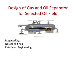
- 1. Design of Gas and Oil Separator for Selected Oil Field . ;;,, Prepared by: Nasser Kalf Aziz Petroleum Engineering NNNHHHHHH HHH
- 2. Outlines Definition of Separator. Functional Sections of a Gas-Liquid Separator Types of oil and gas Separator. Basic functions of oil and gas separators. Figure Types of Separator. Comparison between horizontal separator & vertical separator. Internal Vessel Components. Mist Extractors. Control Components of Gas–Oil Separators. Operating Problems.
- 3. What is the Separator? A cylindrical or spherical vessel used to separate oil, gas and water from the total fluid stream produced by a well laminar flow.
- 4. Basic components of Separator 1- Inlet Diverter Section The inlet stream to the separator is typically a high-velocity turbulent mixture of gas and liquid. Due to the high velocity, the fluids enter the separator with a high momentum. Collision or abruptly changes the direction of flow by absorbing the momentum of the liquid and allowing the liquid and gas to separate. This results in the initial “gross” separation of liquid and gas. The inlet diverter, sometimes referred to as the primary separation section. Therefor this section is used to reduce the momentum of the inlet flow stream, perform an initial bulk separate ion of the gas and liquid phases, and enhance gas flow distribution. There are varieties of inlet devices available and these will be discussed in more detail in a later section.
- 5. Basic components of Separator 2- Liquid Collection Section The liquid collection section, located at the bottom of the vessel, it acts as a receiver for all liquid removed from the gas in the inlet, gas gravity, and mist extraction sections. The liquid collection section provides the required retention time necessary for any entrained gas in the liquid to escape to the gravity settling section. In addition, it provides a surge volume to handle intermittent slugs. In three-phase separation applications, the liquid gravity section also provides residence time to allow for separation of water droplets from a lighter hydrocarbon liquid phase and vice- versa. Due to the smaller difference in gravity between crude oil and water, compared to gas and liquid in two-phase separation, Liquid-liquid separation requires longer retention times than gas-liquid separation
- 6. Basic components of Separator 3-Gravity Settling Section As the gas stream enters the gravity settling section, its velocity drops and small liquid droplets that were entrained in the gas and not separated by the inlet diverter are separated out by gravity and fall to the gas liquid interface, preconditioning the gas for final polishing by the mist extractor. The gravity settling section is sized so that liquid droplets greater than 100 to 140 microns fall to the gas-liquid interface while smaller liquid droplets remain with the gas. Liquid droplets greater than 100 to 140 microns are undesirable as they can overload the mist extractor at the separator outlet .In some horizontal designs, straightening vanes are used to reduce turbulence. The vanes also act as droplet coalescers, which reduces the horizontal length required for droplet removal from the gas stream
- 7. Basic components of Separator 4-Mist Extractor Section Gas leaving the gravity settling section contains small liquid droplets, generally less than 100 to 140 microns. Before the gas leaves the vessel, it passes through a coalescing section or mist extractor. This section uses coalescing elements that provide a large amount of surface area used to coalesce and remove the small droplets of liquid. As the gas flows through the coalescing elements, it must make numerous directional changes. Due to their greater mass, the liquid droplets cannot follow the rapid changes in direction of flow
- 9. Types of oil and gas Separator 1-Vertical Separators Vertical separators, shown in Fig. 2, are usually selected when the gas-liquid ratio is high or total gas volumes are low. In a vertical separator, the fluids enter the vessel through an inlet device whose primary objectives are to achieve efficient bulk separation of liquid from the gas and to improve flow distribution of both phases through the separator. Liquid removed by the inlet device is directed to the bottom of the vessel. The gas moves upward in the gravity settling section, where the liquid droplets fall vertically downward counter-current to the upward gas flow. The settling velocity of a liquid droplet is directly proportional to its diameter. If the size of a liquid droplet is too small, it will be carried up and out with the vapor. Thus, a mist extractor section is added to capture small liquid droplets. Liquid removed by the mist extractor is coalesced into larger droplets that then fall through the gas to the liquid reservoir in the bottom. Liquid continues to flow downward through liquid collection section to the liquid outlet. As the liquid reaches equilibrium, gas bubbles flow counter to the direction of the liquid flow and eventually migrate to the vapor space. In this service the vertical separator: • Does not need significant liquid retention volume • A properly designed liquid level control loop responds quickly to any liquid that enters, thus avoiding tripping an alarm or shutdown • The separator occupies a small amount of plot space.
- 11. Types of oil and gas Separator 2- Horizontal Separator Figure 3 displays a schematic diagram of a horizontal Separator. In a Horizontal Separator, the gas flows horizontally while the liquid droplets fall towards the surface of the liquid. Wet gas flows into the Separator surface and forms a liquid film which is discharged away to the liquid separator. The beams must be longer than the travel distance of the fluid path. The liquid level control position is more important in the horizontal separator than in the vertical separator because of the limited increase area.
- 12. Figure (3) A typical horizontal Separator
- 13. Types of oil and gas Separator 3-Spherical Separator Spherical Separators provide an inexpensive and compact means of arranging insulation. Due to compact configurations, this type of separator has very limited flow area and gravitational stability section of the liquid. Also, the placement and functioning of the liquid level control in this type of Separator is critical.
- 14. Figure (6) a spherical Separator
- 15. Basic functions of oil and gas separators 1- Removing oil from the gas 2- Removing gas from oil 3- Isolate water from oil 4- Maintain optimum pressure separator 5- Maintain a liquid seal in the separator
- 17. Comparison between horizontal separator & vertical separator separators used in oilfields can be divided into horizontal separators and vertical separators according to the installation methods. According to its performance, it can also be divided into test separator, production separator, oil-gas two-phase separator and oil-gas- water three-phase separator. Generally, horizontal separator is the popular choice for customers due to its wide range of applications, low unit processing cost, easy for installation, operation and maintenance. Furthermore, with its large gas-liquid interface area, bubbles in crude oil are easy to rise to gas-phase space. Therefore, it has perfect gas-liquid separation effect which can meet customer requirements.
- 19. Internal Vessel Components. 1-Inlet Diverters Inlet diverters serve to impart flow direction of the entering vapor/liquid stream and provide primary separator between the liquid and vapor. There are many types of inlet diverters • No inlet device • Diverter plate • Half-pipe • Reversed pipe (elbow) • Dished head • Vane-type • Cyclonic The main functions of the inlet device are: • Reduce the momentum of the inlet stream and enhance flow distribution of the gas and liquid phases. • Efficient separation of the bulk liquid phase. • Prevent droplet shattering and re-entrainment of bulk liquid phase.
- 21. Internal Vessel Components There are several different types of separator inlet devices that are commonly used: A baffle plate can be a spherical dish, flat plate, angle iron, cone, elbow, or just about anything that will accomplish a rapid change in direction and velocity of the fluids and thus disengage the gas and liquid. At the same velocity the higher-density liquid possesses more energy and, thus, does not change direction or velocity as easily as the gas. Thus, the gas tends to flow around the diverter while the liquid strikes the diverter and then falls to the bottom of the vessel. The design of the baffles is governed principally by the structural supports required to resist the impact- momentum load. The advantage of using devices such as a half-sphere elbow or cone is that they create less disturbance than plates or angle iron, cutting down on re-entrainment or emulsifying problems.
- 22. Internal Vessel Components Centrifugal inlet diverters use centrifugal force, rather than mechanical agitation, to disengage the oil and gas. These devices can have a cyclonic chimney or may use a tangential fluid race around the walls. Centrifugal inlet diverters are generally use an inlet nozzle sufficient to create a fluid velocity of about 20 ft/s around a chimney. Centrifugal diverters can be designed to efficiently separate the liquid while minimizing the possibility of foaming or emulsifying problems. The disadvantage is that their design is rate sensitive. At low velocities they will not work properly. Thus, they are not normally recommended for producing operations where rates are not expected to be steady.
- 25. Internal Vessel Components 2- Wave Breakers In long horizontal vessels, waves may result from surges of liquids entering the vessel or will result if the horizontal vessel is located on a floating structure. Wave breakers are nothing more than perforated baffles or plates that are placed perpendicular to the flow located in the liquid collection section of the separator. These baffles dampen any wave action that may be caused by incoming fluids. The wave actions in the vessel must be eliminated so level controls, level switches, and weirs may perform properly. is a three- dimensional view of a horizontal separator fitted with an inlet diverter,
- 26. Internal Vessel Components 3- Defoaming Plates Foam at the interface may occur when gas bubbles are liberated from the liquid. Foam can severely degrade the performance of a separator. This foam can be destabilized with the addition of chemicals at the inlet, but the more effective solution is to force the foam to pass through a series of inclined parallel plates or tubes as shown in Figure These closely spaced, parallel plates or tubes provide additional surface area, which breaks up the foam and allows the foam to collapse into the liquid layer.
- 27. Internal Vessel Components 4- Vortex Breaker Liquid leaving a separator may form vortices or whirlpools, which can pull gas down into the liquid outlet. Therefore, horizontal separators are often equipped with vortex breakers, which prevent a vortex from developing when the liquid control valve is open. A vortex could suck some gas out of the vapor space and re-entrain it in the liquid outlet. One type of vortex breaker is shown in Figure. It is a covered cylinder with radially directed flat plates. As liquid enters the bottom of the vortex breaker, any circular motion is prevented by the flat plates. Any tendency to form vortices is removed. illustrates other commonly used vortex breakers.
- 29. Internal Vessel Components 5- Stilling Well A stilling well, which is simply a slotted pipe fitting surrounding an internal level control displacer, protects the displacer from currents, waves, and other disturbances that could cause the displacer to sense an incorrect level measurement
- 30. Internal Vessel Components 6- Sand Jets and Drains In horizontal separators, one worry is the accumulation of sand and solids at the bottom of the vessel. If allowed to build up, these solids will upset the separator operations by taking up vessel volume. Generally, the solids settle to the bottom and become well packed. To remove the solids, sand drains are opened in a controlled manner, and then high-pressure fluid, usually produced water, is pumped through the jets to agitate the solids and flush them down the drains. The sand jets are normally designed with a 20-ft/s, jet tip velocity and aimed in such a manner to give good coverage of the vessel bottom.
- 32. Mist Extractors 1- Introduction Mist extractors or mist eliminators or demister, are names of an equipment used to remove the liquid droplets and solid particles from the gas stream. All mist extractor types are based on the some kind of intervention in the natural balance between gravitational and drag forces. This is accomplished in one or more of the following ways: • Overcoming drag force by reducing the gas velocity (gravity separators or settling chambers) • Introducing additional forces (venturi scrubbers, cyclones.) • Increasing gravitational force by boosting the droplet size (impingement-type) The following factors should be considered before selection: • Size of droplets the equipment must remove • Accepted pressure drop across the mist extractor • Susceptibility of the equipment to plugging by solids, if solids are present • Liquid handling capability of the equipment • Whether the mist extractor/eliminator can be installed inside existing vessel, or if it requires a standalone vessel instead • Cost of the mist extractor/eliminator itself and required vessels, piping, instrumentation, and utilities
- 33. Mist Extractors 2- Impingement-Type Mist Extractor Impingement-type mist extractor is the most widely used type of mist extractors because it offers good balance between efficiency, operating range, pressure drop requirement, and installed cost. These types consist of baffles, wire meshes, and micro-fiber pads. Impingement-type mist extractors may involve just a single baffle or disc installed in a vessel. As illustrated in Figure 8, as the gas approaches the surface of the baffle or disc (commonly referred to as a target), fluid streamlines spread around the baffle or disc. The higher the stream velocity, the closer to the target these streamlines start to form. A droplet can be captured by the target in an impingement-type mist extractor/eliminator via any of the following three mechanisms: inertial impaction, direct interception, and diffusion (Fig. A and B).
- 34. Mist Extractors
- 35. Mist Extractors • Inertial impaction. Because of their mass, particles 1 to 10 microns in diameter in the gas stream have sufficient momentum to break through the gas streamlines and continue to move in a straight line until they impinge on the target. Impaction is generally the most important mechanism in wire mesh pads and impingement plates. • Direct interception. There are also particles in the gas stream that are smaller, between 0.3 to 1 microns in diameter, than those above. These do not have sufficient momentum to break through the gas streamlines. Instead, they are carried around the target by the gas stream. However, if the streamline in which the particle is traveling happens to lie close enough to the target so that the distance from the particle centerline to the target is less than one-half the particle’s diameter, the particle can touch the target and be collected. Interception effectiveness is a function of pore structure. The smaller the pores, the greater the media to intercept particles. • Diffusion. Even smaller particles, usually smaller than 0.3 microns in diameter, exhibit random Brownian motion caused by collisions with the gas molecules. This random motion will cause these small particles to strike the target and be collected, even if the gas velocity is zero. Diffusion is favored by low velocity and high-concentration gradients.
- 36. Mist Extractors 3- Baffles (Vane Type) mist extractor This type of impingement mist extractor consists of a series of baffles, vanes, or plates between which the gas must flow. The most common is the vane or chevron-shape, as shown in Figures 2-29, 2-30, and 2-31. The vanes force the gas flow to be laminar between parallel plates that contain directional changes. The surface of the plates serves as a target for droplet impingement and collection. A number of different vane pack designs are available. Pack thicknesses are generally in the range of 6–12 inches. Vanes are usually arranged in a zig-zag or sinusoidal pattern, The space between the baffles ranges from 5 to 75 mm, with a total depth in the flow direction of 150 to 300 mm. illustrate a vane mist extractor installed in a vertical and horizontal separator, respectively. Figure 2-34 shows a vane mist extractor made from an angle iron. Figure 2-35 illustrates an “arch” plate mist extractor. As gas flows through the plates, droplets impinge on the plate surface. The droplets coalesce, fall, and are routed to the liquid collection section of the vessel. Vane-type eliminators are sized by their manufacturers to assure both laminar flow and a certain minimum pressure drop. Vane or chevron-shaped mist extractors remove liquid droplets 10 to 40 microns and larger.
- 37. Mist Extractors
- 38. Mist Extractors Separation Performance The operation and performance is usually dictated by a design velocity expressed as follows: Vt = K [(ρl - ρg ) / ρg]0.5 where V = gas velocity, ft/s K = Souders–Brown coefficient, ρl = liquid or droplet density, lb/ft3 ρg = gas density, lb/ft3 The “K” factor or Souders–Brown coefficient, is determined experimentally for each plate geometry. Its value ranges from 0.3 to 1.0 ft/s in typical designs. Since impaction is the primary collection mechanism, at too low a value of “K” the droplets can remain in the gas streamlines and pass through the device uncollected. The upper limit is set to minimize re-entrainment, which is caused either by excessive breakup of the droplets as they impinge onto the plates or by shearing of the liquid film on the plates. Vane-type mist extractors are also impacted by inlet liquid loading, but generally have considerably more tolerance towards liquids than mesh-pads. The required mist extractor area is obtained from A = Qg / Vt where A = area of mist extractor (ft2) Qg = actual gas flow rate, ft3/sec
- 39. Mist Extractors 4- Wire-Mesh mist extractor Wire-mesh mist extractors, or pads, are made by knitting wire, metal or plastic, into tightly packed layers which are then crimped and stacked to achieve the required pad thickness. If removal of very small droplets, i.e. less than 10 micron, is required, much finer fibers may be interwoven with the primary mesh to produce a co-knit pad. Mesh pads remove liquid droplets mainly by impingement of droplets onto the wires and/or co-knit fibers followed by coalescence into droplets large enough to disengage from the bottom of the pad and drop through the rising gas flow into the liquid holding part of the separator. Mesh pads are not recommended for dirty or fouling service as they tend to plug easily. Wire-mesh is the most common type of mist extractor found in production operations Most installations will use a 6-inch thick pad with 9-12 lb/ft3 bulk density. Minimum recommended pad thickness is 4 inches. They are usually constructed from wires of diameter ranging from 0.10 to 0.28 mm, with a typical void volume fraction of 0.95 to 0.99. The wire pad is placed between top and bottom support grids near the outlet of a separator, generally on a support ring (vertical separator) or frame (horizontal separator). Wire-mesh mist extractors are normally installed in vertical upward gas flow, although horizontal flows are employed in some specialized applications. In a horizontal flow the designer must be careful because liquid droplets captured in the higher elevation of the vertical mesh may drain downward at an angle as they are pushed through the mesh, resulting in re-entrainment.
- 40. Mist Extractors
- 41. Mist Extractors 5- Micro-Fiber Micro-fiber mist extractors use very small diameter fibers, usually less than 0.02 mm, to capture very small droplets. Gas and liquid flow is horizontal and co-current. Because the micro-fiber unit is manufactured from densely packed fiber, drainage by gravity inside the unit is limited. Much of the liquid is eventually pushed through the micro-fiber and drains on the downstream face. The surface area of a micro-fiber mist extractor can be 3 to 150 times that of a wire-mesh unit of equal volume
- 42. Mist Extractors 6-Other Configurations Some separators use centrifugal mist extractors, discussed earlier in this chapter, that cause liquid droplets to be separated by centrifugal force These units can be more efficient than either wire-mesh or vanes and are the least susceptible to plugging. However, they are not in common use in production operations because their removal efficiencies are sensitive to small changes in flow. In addition, they require relatively large pressure drops to create the centrifugal force. To a lesser extent, random packing is sometimes used for mist extraction, as shown in The packing acts as a coalescer . 7- Final Selection The selection of a type of mist extractor involves a typical cost-benefit analysis. Wire- mesh pads are the cheapest, but mesh pads are the most susceptible to plugging with paraffins , gas hydrates, etc. With age, mesh pads also tend to deteriorate and release wires and/or chunks of the pad into the gas stream. This can be extremely damaging to downstream equipment, such as compressors. Vane units, on the other hand, are more expensive. Typically, vane units are less susceptible to plugging and deterioration than mesh pads. Micro-fiber units are the most expensive and are capable of capturing very small droplets but, like wire mesh pads, are susceptible to plugging. The selection of a type of mist extractor is affected by the fluid characteristics, the system requirements, and the cost.
- 43. Mist Extractors
- 44. Control Components of Gas–Oil Separators Gas–oil separators are generally equipped with the following control devices and internal components. Liquid Level Controller The liquid level controller (LLC) is used to maintain the liquid level inside the separator at a fixed height. In simple terms, it consists of a float that exists at the liquid–gas interface and sends a signal to an automatic valve on the oil outlet. The signal causes the valve to open or close, thus allowing more or less liquid out of the separator to maintain its level inside the separator. Pressure Control Valve The pressure control valve (PCV) is an automatic backpressure valve that exists on the gas stream outlet. The valve is set at a prescribed pressure. It will automatically open or close, allowing more or less gas to flow out of the separator to maintain a fixed pressure inside the separator. Pressure Relief Valve The pressure relief valve (PRV) is a safety device that will automatically open to vent the separator if the pressure inside the separator exceeded the design safe limit. Shut down valves Shut down valves are usually installed at the inlet of separator to protect the vessel by preventing the incoming flow in case of vessel high pressure or high liquid level. Also it is usually installed at the outlet lines to prevent the flow out in case of very low liquid level or very low pressure. uid out of the separator to maintain its level inside the separator.
- 45. Operating Problems 1- Foamy Crude The major cause of foam is the presence of impurities other than water in crude. One impurity that always causes foam is CO2. Work over fluids sometimes may be incompatible with the wellbore fluids, and will cause foam. Foam presents no problem within a separator if the internal design assures adequate time or sufficient coalescing surface for the foam to “break.” Foaming in a separating vessel is a problem due to: 1. Foam will occupy a large space in the separator that otherwise would be available for the separation process; therefore, the separator efficiency will be reduced. 2. The foam will disrupt the operation of the level controller, since it has a density between that of the liquid and gas. 3. In case of existence of a foam bank, it will be possible for some of the foam to escape with gas outlet or with liquid outlet. Causing a problem in both cases. 2- Paraffin Separator operation can be adversely affected by an accumulation of paraffin. Coalescing plates in the liquid section and mesh pad mist extractors in the gas section are particularly prone to plugging by accumulations of paraffin. Where it is determined that paraffin is an actual or potential problem, the use of plate-type or centrifugal mist extractors should be considered. Manways , handholes , and nozzles should be provided to allow steam, solvent, or other types of cleaning of the separator internals. The bulk temperature of the liquid should always be kept above the cloud point of the crude oil.
- 46. Operating Problems 3- Sand Accumulation of san in the bottom of separators is serious operation problem, causing separator size reduction, cutout of valve trim, and plugging of separator internals. Accumulations of sand can be removed by periodically injecting water or steam in the bottom of the vessel so as to suspend the sand during drainingis a cutaway of a sand wash and drain system fitted into a horizontal separator fitted with sand jets and an inverted trough. Sometimes a vertical separator is fitted with a cone bottom. This design would be used if sand production was anticipated to be a major problem. The cone is normally at an angle of between 450 and 600 to the horizontal. If a cone is installed, it could be part of the pressure-containing walls of the vessel, or for structural reasons, it could be installed internal to the vessel cylinder In such a case, a gas equalizing line must be installed to assure that the vapor behind the cone is always in pressure equilibrium with the vapor space.
- 48. Operating Problems 4- Gas Blowby Gas blowby occurs when free gas escapes with the liquid phase and can be an indication of low liquid level, vortexing, or level control failure. This could lead to a very dangerous situation. If there is a level control failure and the liquid dump valve is open, the gas entering the vessel will exit the liquid outlet line and would have to be handled by the next downstream vessel in the process. Unless the downstream vessel is designed for the gas blowby condition, it can be over-pressured. Gas blowby can usually be prevented by installing a level safety low sensor (LSL) that shuts in the inflow and/or outflow to the vessel when the liquid level drops to 10–15% below the lowest operating level. In addition, downstream process components should be equipped with a pressure safety high (PSH) sensor and a pressure safety valve (PSV) sized for gas blowby. 5- Liquid Carryover Liquid carryover occurs when free liquid escapes with the gas phase and can indicate high liquid level, damage to vessel internals, foam, improper design, plugged liquid outlets, or a flow rate that exceeds the vessel’s design rate. Liquid carryover can usually be prevented by installing a level safety high (LSH) sensor that shuts in the inlet flow to the separator when the liquid level exceeds the normal maximum liquid level by some percentage, usually 10–15%.