Pioneering Large Diamond Recovery at Karowe Diamond Mine_Ref Comments_11-12-2015
1. PIONEERING LARGE DIAMOND RECOVERY AT
KAROWE DIAMOND MINE
ABSTRACT
Historically, large diamond recovery in conventional treatment plant flowsheets has been associated
with dense media separation (DMS) as an ore beneficiation technique. This is mainly attributed to its
highly efficient and proven track record as a successful method in the concentration and separation of
ores with variable solids densities. In most instances, dense media separation has been recognised and
utilised as a pre-concentration step ahead of any Recovery plant due to its ability and versatility in
reducing DMS feed ore within a specific size range to manageable volumes required for downstream
X-Ray processing and subsequent diamond recovery. The benefit of using carbon signature based
detection equipment in retrieving large stones upfront in the flowsheet not only equates to earlier
beneficiation of diamonds from the system, but also promotes the reduction of diamond-bearing ore
exposure to additional materials handling, pumping and/or crushing which has been known to damage
or even break product and decrease revenue as part of the overall value chain.
INTRODUCTION
The selection of X-ray transmission (XRT) for kimberlite sorting lies in the advantage of the material
presentation. Detection with XRT is dependent on the atomic number of the material to be the detected.
The sorting ability and effectiveness of X-ray transmission lies in variance of the atomic number of
material A and B that need to be separated from each other. The advantage of this technique is that the
presentation of the material is of lesser importance. Unlike Near-Infrared (NIR) and X-ray
Luminescence (XRL), XRT is not dependant on a clean, visibly colour different or reflective particle
surfaces. XRT technology has a significantly higher detection of Type II diamonds compared to
traditional XRL sorters with an order of magnitude lower yield percentage. XRT sorters delivers a
significantly lower percentage yield than traditional DMS plants with a vastly reduced running cost
relating to consumables and utilities.
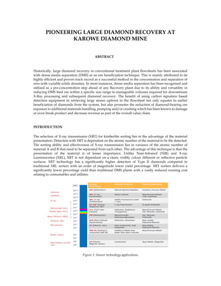
Figure 1: Sensor technology applications
2. A broad-band electrical X-ray source is applied to the material to be sorted while it is moving along the
belt.
Figure 2: XRT sorter material discrimination
The X-ray sensor system below the material produces a digital image of the material being sorted, using
two different energy bands. The X-ray attenuation through the material is different between the two
bands and depends on both the material's thickness and density. An image transformation of the density
images of the two bands then enables the classification of each pixel according to its average atomic
density.
Figure 3: Dual XRT sensing
Figure 4: XRT imaging
3. Figure 5: XRT automated sorting principle
Classification of each pixel proceeds relative to a reference density against which the system has been
calibrated. A complete particle will then be classified according to the overall classification of the pixels
within the particle. Depending on the classification, the selected particles are either “ejects”, diverted
upwards by air jets out of the overall material stream (material stream B) or “accepts” in the other stream
(material stream A). It is important to note that “eject” refers to the material that the system has been
configured to blow out of the material stream, this can be either the waste or the product.
XRT CIRCUIT DESIGN, COMMISSIONING & PERFORMANCE
XRT Layout (including Audit XRT): The Karowe XRT section, as part of the greater Karowe Plant
Upgrade circuit, is found post autogenous (AG) milling where a DMS/Bulk Sorter Sizing Screen is
utilised to separate the XRT feed envelope from the -8 mm DMS feed and also any -1.5 mm fine effluent
generated in the circuit due to particle breakdown via materials handling, transfers and recycling.
The DMS/Bulk Sorter Sizing Screen is key to the circuit in Figure 6 due to its central positioning in
receiving milled ore, tertiary crusher product and also pebble crusher “bleed” fraction (i.e. pebble
crusher recycle by-pass not re-directed back to mill feed for load management requirements). From the
DMS/Bulk Sorter Sizing Screen, the feed is split into the following three streams:
• -60 +8 mm fraction is wet screened and fed to the XRT section.
• -8 +1.5 mm fraction is wet screened and fed to the existing DMS for gravity concentration.
• -1.5 mm envelope is removed as effluent to the degrit circuit for grits removal and dewatering
purposes. There is little to no value in the effluent stream hence the reason for removal and
dewatering.
Moving away from the DMS/Bulk Sorting Sizing Screen and down to the XRT section, the -60 +8 mm
is further separated via Bulk Sorter Sizing Screen at the top of the XRT building into the following
streams:
• Large Diamond Recovery (x 1 stream) -60 +32 mm
• Coarse XRT (x 2 streams) -32 +14 mm
• Middles XRT (x 2 streams) -14 +8 mm
5. Figure 8: Karowe’s XRT section during construction (Q2 2015)
To recover large diamonds in the various XRT size fractions as set out above, each individual size
fraction stream’s processing route utilises bin(s) and variable speed belt feeder(s) to “match” each
associated XRT’s size-specific throughput application. Feed presentation ahead of each XRT machine
was a critical factor evaluated during the design phase: a vibrating feeder ahead of the XRT machine
accepts feed from the upstream belt feeder and introduces an evenly distributed mono layer feed to the
XRT feed belt typically running at speeds of up to ~3 m/s. The following table below best illustrates the
throughput-size fraction relationship applicable to Karowe’s Bulk Sorting section:
Table I: XRT Throughput vs size fraction treatment
Maximum Machine Throughput – Karowe Plant Specific
Description Size Fraction Throughput (tph)
Large Diamond Recovery
(LDR) XRT Bulk Sorting
-60 +32 mm 150
Coarse XRT Bulk Sorting -32 +14 mm 100
Middles XRT Bulk Sorting -14 +8 mm 60
Feed moisture content (percentage solids by weight) from upstream washing/sizing was also
instrumental to the design, as any value in excess of 8 percent surface moisture (by weight) will cause
unnecessary fines build-up in the Bulk Sorting section and detrimentally impact on machine
performance. Supporting utility services were also crucial for each and every XRT performing to its
optimum efficiency; by utilising compressed air and chilled water as essential services to the machines,
diamond concentrate could be adequately “ejected” from each sized stream with chiller water
effectively cooling down the respective x-ray tubes for continuous successful operation. Tables II and
III capture the chiller water and compressed air services data. The data were required during design
and subsequent operation of the Karowe XRT sorter machines.
6. Table II: Chiller water requirements per Karowe XRT sorter
Description Value / Comment
Water Circuit Flowrate (l/min) 10
Water Pressure at Machine Inlet (bar) 4.5
Maximum Operating Temperature (˚C) 40
Water Inlet Temperature (˚C)
(Chiller pipes require isolation lagging to keep fluid temperature
down to a minimum before feed entry into machines)
25
Cooling Capacity Required (kW, accumulated heating energy)
4 kW X-Ray Source
4 kW Generator
8
Coolant
High Glycol content;
≤ 10 percent concentration
Table III: Consumed air requirements per tonne of feed ejected
Description Value
Large Diamond Recovery (LDR) XRT Bulk Sorting (m3/hr)
20
(Based on 1% material ejection rate)
Coarse XRT Bulk Sorting (m3/hr)
25
(Based on 1% material ejection rate)
Middles XRT Bulk Sorting (m3/hr)
50
(Based on 1% material ejection rate)
Cold commissioning (C3) with regards to the Karowe XRT machines were completed on the 15th of April
2015. These included the following vendor-specific activities:
• Splicing of new sorter belts.
• Electrical wiring of the sorters.
• Sorter calibrations and sorting algorithms.
• Tracer testing without material.
• Diamond testing without material.
During the tracer and diamond testing without material, the following tracer and diamond quantities
with associated specifications were adopted and utilised to calibrate, set up and test individual machine
performances. Aspects requiring set up and testing included white balance, nozzle to pixel mapping,
divergence, and establishing the various calibration curves.
Table IV: Karowe XRT tracer and diamond specifications used during cold commissioning
Material Size Fraction (mm)
Number & of Cubic
Carbon Tracers Used
Tracer
Dimensions (mm)
Minimum Diamond
Size Range (mm)
LDR: -60 +32 mm
@ 150 tph
500 @ 98% expected
recovery
50 x 50 x 50
24.26 x 20.12 x 24.12
(tracer diamond #52)
Coarse: -32 +14 mm
@ 100/200 tph
(Throughput per sorter /
Overall throughput)
500 @ 98% expected
recovery
15 x 15 x 15
11.14 x 11.03 x 9.51
(tracer diamond #25)
Middles: -14 +8 mm
@ 43/86 tph
(Throughput per sorter /
Overall throughput)
500 @ 98% expected
recovery
10 x 10 x 10
6.54 x 6.83 x 6.99 (tracer
diamond #52)
Following the cold commissioning activities that concluded on the 15th of April, the project moved into
a hot commissioning phase (C4) with the following listed activities that occurred soon after:
7. • Tracer testing with material feed.
• Production ramp-up.
• Production optimisation.
Tracer results obtained during hot commissioning of the XRT sorters can be viewed in Tables V to IX.
Table V: Karowe LDR (-60 +32 mm) XRT sorter tracer test results
Tracer Test No.
Totaliser
Start
(tonnes)
Totaliser
Stop
(tonnes)
Tonnes Treated
during Tracer
Test
Number of
Tracers added
to Ore Feed
% Tracer
Recovery
1 5.8 14.0 8.2 100 100
2 14.0 26.2 12.2 100 100
3 26.2 33.9 7.7 100 100
4 33.9 46.5 12.6 100 100
5 46.5 54.3 7.8 100 100
Total / Average - - 48.5 (total) 500 (total)
100
(average)
Average Throughput Range during
all Tracer Test Runs (tph)
100 – 153
% VSD Setting on Belt Feeder
Feeding XRT Sorter
20 (Tests 1, 2) & 38 – 42 (Tests 3, 4 & 5)
Table VI: Karowe Coarse 1 (-32 +14 mm) XRT sorter tracer test results
Tracer Test No.
Totaliser
Start
(tonnes)
Totaliser
Stop
(tonnes)
Tonnes Treated
during Tracer
Test
Number of
Tracers added
to Ore Feed
% Tracer
Recovery
1 12.4 18.6 6.2 100 100
2 18.6 24.1 5.5 100 100
3 24.1 29.0 4.9 100 100
4 29.0 33.6 4.6 100 100
5 33.6 37.4 3.8 100 100
Total / Average - - 25.0 (total) 500 (total)
100
(average)
Average Throughput Range during
all Tracer Test Runs (tph)
100 – 120
% VSD Setting on Belt Feeder
Feeding XRT Sorter
25
Table VII: Karowe Coarse 2 (-32 +14 mm) XRT sorter tracer test results
Tracer Test No.
Totaliser
Start
(tonnes)
Totaliser
Stop
(tonnes)
Tonnes Treated
during Tracer
Test
Number of
Tracers added
to Ore Feed
% Tracer
Recovery
1 3.0 8.8 5.8 100 100
2 8.8 13.8 5.0 100 100
3 13.8 18.6 4.8 100 100
4 18.6 24.8 6.2 100 100
5 24.8 29.4 4.6 100 100
Total / Average - - 26.4 (total) 500 (total)
100
(average)
Average Throughput Range
during all Tracer Test Runs (tph)
90 – 130
% VSD Setting on Belt Feeder
Feeding XRT Sorter
25
8. Table VIII: Middles 1 (-14 +8 mm) XRT sorter tracer test results
Tracer Test No.
Totaliser
Start
(tonnes)
Totaliser
Stop
(tonnes)
Tonnes
Treated
during Tracer
Test
Number of
Tracers added
to Ore Feed
% Tracer
Recovery
1 34.8 38.3 3.5 100 100
2 38.3 41.0 2.7 100 98
3 41.0 44.3 3.3 100 100
4 44.3 47.0 2.7 100 100
5 47.0 49.4 2.4 100 99
Total / Average - - 14.6 (total) 500 (total)
99.4
(average)
Average Throughput Range
during all Tracer Test Runs
(tph)
40 – 43
% VSD Setting on Belt Feeder
Feeding XRT Sorter
13
Table IX: Karowe Middles 2 (-14 +8 mm) XRT sorter tracer test results
Tracer Test No.
Totaliser
Start
(tonnes)
Totaliser
Stop
(tonnes)
Tonnes Treated
during Tracer
Test
Number of
Tracers added
to Ore Feed
% Tracer
Recovery
1 46.9 50.9 1.3 100 100
2 50.9 52.1 1.2 100 100
3 52.1 53.3 1.2 100 99
4 53.3 54.6 1.3 100 100
5 54.6 55.8 1.2 100 100
Total / Average - - 6.2 (total) 500 (total) 99.8 (average)
Average Throughput
Range during all Tracer
Test Runs (tph)
41 – 44
% VSD Setting on Belt
Feeder Feeding XRT
Sorter (on SCADA)
13
Average yields achieved during above tracer tests in material feed were in the order of ~ 1.3 to
8.0 x 10⁻⁵ % with an associated calculated product yield range of ~0.3 to 1.2 kg/day. Hot commissioning
ceased on the 27th of April 2015 where the XRT sorters were subsequently handed over to the Boteti
client for normal production running. Continued production performance monitoring also occurred
post XRT handover for another period of 28 days until this was completed on the 25th of May 2015.
Further XRT optimisation was required and completed on the challenges experienced post production
running. These challenges were:
• Low air consumption and air inlet pressure: mitigating action involved separating the LDR XRT
separator from the rest of the XRT compressed air circuit with its own dedicated stand-alone
compressor unit.
• Low chiller water inlet flow: matter resolved on site through small system adjustment.
• Occasional fines carry-over from DMS/Bulk Sorter Sizing Screen: this was alleviated by optimising
the spray and wash water requirements associated upstream with the DMS/Bulk Sorter Sizing
Screen.
On 18 November 2015, Karowe mine made history when Lucara Diamond Corporation reported the
recovery of an 1111 carat, white Type IIa stone weighing 222 grams and measuring 65 mm x 56 mm x
40 mm. This is the second largest gem quality stone in history – beaten only by the massive Cullinan
9. diamond discovered in 1905 and weighing 3106 carats. Karowe mine also recovered an 813 carat, white
Type IIa diamond soon after the 1111 carat find - which is the sixth largest gem quality stone also ever
recovered.
FUTURE XRT UPGRADES ENVISAGED AT KAROWE MINE
Due to the prevalence of very large diamonds at Karowe, the mine has opted to evaluate the possibility
of a very large diamond recovery (VLDR) section close to the current secondary crushing area. A
potential design is to investigate keeping the sorting and comminution aspects separate from a process
perspective so that the undersize scalping associated with comminution purposes can be changed
independently of the VLDR sorter. In a nutshell, a proposed design will consider:
• All primary crusher ROM product to be scalped at 60 or even 50 mm with the -60/50 mm undersize
reporting directly to the AG mill.
• Inclusion of a 125 mm grizzly screen ahead of secondary crushing to treat the oversize fraction from
the scalping screen: with the -125 +50 mm middles envelope directed to the VLDR sorter(s) for
diamond recovery.
• Tailings from the new VLDR sorter(s) will subsequently recombine with the +125 mm grizzly
oversize material and subjected to the existing proportional splitter ahead of the secondary crushing
section: undergoing the same crusher/bypass operational split flexibility of 25, 50, or 75 % as is
currently the case.
REFERENCES
Riedel, F., Dehler, M. (2010). Recovery of unliberated diamonds by X-ray transmission sorting.
Proceedings of the fourth Diamonds: Source to Use Conference. The South African Institute of Mining and
Metallurgy. Gaborone, Botswana. pp. 193-200.
Von Ketelhodt, L. (2012). Tomra Sorting Solutions. Regional Meeting. The South African Institute of Mining
and Metallurgy. Johannesburg. South Africa. Presentation.
Van Niekerk, L.M., Ndlovu, G.N., Sikwa, N.A. (2013). Commissioning and Operating an Autogenous
Mill at Karowe Diamond Mine. Proceedings of the fifth Diamonds: Source to Use Conference. The South
African Institute of Mining and Metallurgy. Muldersdrift, South Africa. pp. 175-192.
Morgan, P., Van Niekerk, L.M., Underwood, G., Paz, A. (2015). Introduction of Turbo-lifter System at
Karowe Diamond Mine & Comminution Circuit Upgrade. Proceedings of the Sixth International Conference
on Semi-autogenous & High Pressure Grinding Technology. Vancouver, Canada. Extended abstract for
poster presentation.
Financial Post. (2015). Canadian miner Lucara finds 1,111-carat diamond – believed to be second largest
ever.
http://business.financialpost.com/news/mining/canadian-miner-lucara-uncovers-1111-carat-
diamond-believed-to-be-second-largest-ever-found [accessed 14 Dec. 2015].
ACKNOWLEDGEMENTS
The authors are grateful to the following individuals:
• William Lamb, Lucara Diamond Corp;
• Paul Day, Lucara Diamond Corp;
• Gerald Ndlovu, Boteti Mining;
• John Maketo, Boteti Mining;
10. • Boteti Process, Lab and Security teams;
• Fabien Riedel, Tomra Sorting Solutions;
• Geoffrey Madderson, Tomra Sorting Solutions;
• Gavin Underwood, Minopex Botswana;
• Paul Morgan, DRA Mineral Projects;
• Matthew Duddy, DRA Mineral Projects;
• Bennie Viljoen, DRA Mineral Projects;
• Reuben Moalosi, DRA Mineral Projects;
• Cornelius Ntsomeng, DRA Mineral Projects;
• Gavin Outhwaite, DRA Mineral Projects;
• DRA Construction and Commissioning teams.