Excellent ppt on network. Nobody has ever done such things in life. Better watch it or see it or doenload it or think it. The cable tv described in great manner.
The devices such that is very nicely captured. Allow this to download and cable tv is rocking tv
Call US Pooja 9892124323 ✓Call Girls In Mira Road ( Mumbai ) secure service,
Cable TV Network.pptx
1. 1
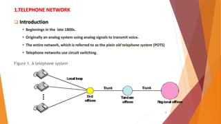
1.TELEPHONE NETWORK
Introduction
• Beginnings in the late 1800s.
• Originally an analog system using analog signals to transmit voice.
• The entire network, which is referred to as the plain old telephone system (POTS)
• Telephone networks use circuit switching.
Figure 1. A telephone system
2. 2
1.TELEPHONE NETWORK (contd..)
Major Components of telephone system:
Local Loops: 1). A twisted-pair cable that connects the subscriber telephone to the
nearest end office or local central office
2) . Its B.W is 4000hz for voice communication.
3) . The first three digits of a local telephone number define the office, and
the next four digits define the local loop number
Trunks : 1) Trunks are transmission media that handle the communication between
offices.
2) A trunk normally handles hundreds or thousands of connections through
multiplexing.
3) Transmission is usually through optical fibers or satellite links.
3. 3
Major Components of telephone system( cont…):
Switching Offices : 1). To avoid having a permanent physical link between any two
subscribers, the telephone company has switches located in a
switching office.
2). Switch connects several local loops or trunks and allows a
connection between different subscribers.
4. 4
Local-Access Transport Areas (LATAs)
A LATA can be a small or large metropolitan area.
A small state may have one single LATA; a large state may have several
LATAs.
A LATA boundary may overlap the boundary of a state; part of a LATA can
be in one state, part in another state.
Two types of LATAs Services
1. Intra-LATA Services
2. Inter-LATA Services
5. 5
Types of LATAs Services (cont…)
1. Intra-LATA Services:
The services offered by the common carriers (telephone companies) inside a LATA
are called intra-LATA services.
The carrier that handles these services is called a local exchange carrier (LEC).
Before the Telecommunications Act of 1996 intra-LATA services were granted to
one single carrier. This was a monopoly.
After 1996,more than one carrier could provide services inside a LATA.
The carrier that provided services before 1996 owns the cabling system (local loops)
and is called the Incumbent Local Exchange Carrier (ILEC).
6. 6
Intra-LATA Services (cont’d…):
The new carriers that can provide services are called Competitive Local
Exchange Carriers (CLECs).
CLECs would provide other services such as mobile telephone service, toll
calls inside a LATA.
Figure below shows a LATA and switching offices.
7. 7
2. Inter-LATA Services
The services between LATAs called Inter-LATA Services
These services handled by Interexchange Carriers (IXCs).
IXCs sometimes called long-distance companies, provide communication services
between two customers in different LATAs.
Major companies providing inter-LATA services include AT&T,MCI, WorldCom,
Sprint, Verizon etc..
The IXCs are long-distance carriers that provide general data communications
services including telephone service.
A telephone call going through an IXC is normally digitized, with the carriers using
several types of networks to provide service.
8. 8
Points Of Presence (POP)
Point of presence (POP) connect several LECs and IXCs.
Each IXC that wants to provide interLATA services in a LATA must have a POP in that
LATA.
The LECs that provide services inside the LATA must provide connections so that every
subscriber can have access to all POPs.
Figure : Point of presences (POPs)
9. 9
3.Signaling
The use of signals for controlling communications.
The sending of a signal from the transmitting end of a telecommunication circuit to
inform a user at the receiving end that a message is to be sent.
The information exchange concerning the establishment and control of a
telecommunication circuit and the management of the network, in contrast to user
information transfer
The signaling system was required to perform other tasks such as
• Providing dial tone, ring tone, and busy tone
• Transferring telephone numbers between offices
• Maintaining and monitoring the call
• Keeping billing information
• Maintaining and monitoring the status of the telephone network equipment
• Providing other functions such as caller ID, voice mail, and so on
10. 10
• Two types of signaling are used
in-band signaling
out-of-band signaling
NOTE : In modern telephone networks the tasks of data transfer and signaling are separated :
data transfer is done by one network, signaling by another.
11. 11
Signaling System Seven (SS7) ***
SS7 is a global standard for telecommunications defined by the ITU.
The protocol that is used in the signaling network is called Signaling System Seven (SS7).
The standard defines the procedures and protocol by which network elements in PSTN
exchange information over a digital signaling network to effect wireless (cellular) and
wireline call setup, routing and control.
The SS7 network and protocol are used for:
• Basic call setup, management and tear down.
• Wireless services such as personal communications services (PCS), wireless roaming,
and mobile subscriber authentication.
• Local Number Portability (LNP).
• Toll-free (800/888) and toll (900) wireline services.
• Enhanced call features such as call forwarding, calling party name/number display,
and three-way calling.
• Efficient and secure worldwide telecommunications.
12. 12
Signaling System Seven (SS7) cont…***
It is very similar to the five-layer Internet model, but the layers have different names
as shown below
Figure : Layers in SS7
13. 13
Signaling System Seven (SS7) cont’d..
MTP Level 1: The physical layer in SS7 called message transport part (MTP) level I uses several
physical layer specifications such as T-l (1.544 Mbps) and Digital Carrier (64 kbps).
MTP Level 2 : The MTP level 2 layer provides typical data link layer services such as packetizing,
using source and destination address in the packet header, and CRC for error
checking.
MTP Level 3: The MTP level 3 layer provides end-to-end connectivity by using the datagram
approach to switching. Routers and switches route the signal packets from the
source to the destination.
Transport Layer : The signaling connection control point (SCCP) is used for special services such
as 800-call processing.
14. 14
Signaling System Seven (SS7) cont’d..
Upper Layers: There are three protocols at the upper layers.
1). TUP : Telephone user port (TUP) is responsible for setting up voice calls.
It receives the dialed digits and routes the calls.
2). TCAP : Transaction capabilities application port (TCAP) provides remote calls that let an
application program on a computer invoke a procedure on another computer.
3). ISUP : ISDN user port (ISUP) can replace TUP to provide services similar to those of an
ISDN network.
15. 15
Services Provided by Telephone Networks ***
Telephone companies provide two types of services: Analog and Digital.
Analog Services:
1. Analog Switched Services
2. 800 service
3. wide-area telephone service (WATS).
4. 900 services
5. Analog Leased Service
Digital Services:
1. switched/56 service .
2. digital data service(DDS).
16. Area of
Distinction
Dial- Up DSL
Initial setup
and
connection
Creates a new connection
every time you use the
internet.
Requires an initial, one time syncing
of signals between your computer’s
special DSL modem and the ISP’s
network. Once your computer is
successfully connected to the ISP
through this DSL connection,
it remains constantly connected unless
the phone line, computer or modem is
physically unplugged or turned off.
Use of
Telephone
wiring
“Ties up” the phone line and
disallows its usage for anything
else, requiring the dedicated
use of a telephone line.
The same phone line can service a
phone call and an internet session
simultaneously.
Speed of
connection
Up to ~56,000 bits per second
From 768,000 bits-per-second to
7,100,000 bits-per-second. Effectively
~15 to 100 times faster than dialup.
Comparison of Dial-up modem and DSL Modem
17. 17
4. DIAL- UP MODEMS
Traditional telephone lines can carry frequencies between 300 and 3300 Hz of BW 3000 Hz.
This range is used for transmitting voice
The effective bandwidth of a telephone line being used for data transmission is 2400 Hz,
covering the range from 600 to 3000 Hz.
Figure : Telephone line bandwidth
18. 18
MODEM is a the device: a signal modulator and a signal demodulator.
A modulator creates a bandpass analog signal from binary data. A demodulator recovers
the binary data from the modulated signal.
.
Figure: Modulation/demodulation
4. DIAL- UP MODEMS(cont..)
19. 19
Modem Standards **
Most popular modems available are based on the V-series standards published by the ITU-T
V.32 modem:
It uses a combined modulation and encoding technique called trelliscoded modulation.
The V.32 calls for 32-QAM with a baud rate of 2400.
Because only 4 bits of each symbol represent data, the resulting data total data rate is 4 x 2400 =
9600 bps.
V.32bis Modem:
It was the first of the ITU-T standards to support 14,400-bps transmission.
The V.32bis uses 128-QAM transmission (7 bits/baud with I bit for error control) at a rate of 2400
baud (2400 x 6 = 14,400 bps).
20. 20
Modem Standards (cont’d…)
V.34bis Modem
The V.34bis modem provides a bit rate of 28,800 with a 960-point constellation
Bit rate of 33,600 bps with a 1664-point constellation
V.90 Modem
V.90 modems with a bit rate of 56,000 bps. Also called 56K modems.
These modems may be used only if one party is using digital signaling (such as through ISP).
They are asymmetric in that the downloading rate is a maximum of 56 kbps, while the uploading rate
can be a maximum of 33.6 kbps.
V.92 Modem
The standard above V90 is called V.92.
These modems can adjust their speed, and if the noise allows, they can upload data at the rate of
48 kbps. The downloading rate is still 56 kbps.
The modem has additional features. For example, the modem can interrupt the Internet connection
when there is an incoming call if the line has call-waiting service.
21. 21
Modem Standards (cont’d…)
Why downloading data rate is high and uploading rate low?
Fig: Uploading and
downloading
in 56K modems
22. 22
5.DIGITAL SUBSCRIBER LINE (DSL) ***
Digital subscriber line (DSL) technology is one of the most promising for
supporting high- speed digital communication over the existing local loops.
After traditional modems reached their peak data rate, telephone companies
developed another technology, DSL, to provide higher-speed access to the
Internet.
DSL technology is a set of technologies,i.e
o Asymmetric Digital Subscriber Line (ADSL)
o Very High-bit-rate Digital Subscriber Line (VDSL)
o High-bit-rate Digital Subscriber Line (HDSL)
o Symmetric Digital Subscriber Line (SDSL).
NOTE: The set is often referred to as xDSL, where x can be replaced by A, V, H, or S.
23. 23
5.DIGITAL SUBSCRIBER LINE (DSL) cont..
ADSL ( Asymmetric Digital Subscriber Line)
ADSL, like a 56K modem, provides higher speed in the downstream direction than in
the upstream direction. That is the reason it is called ‘asymmetric’.
Unlike the asymmetry in 56K modems, the designers of ADSL specifically divided the
available bandwidth of the local loop unevenly for the residential customer.
The service is not suitable for business customers who need a large bandwidth in both
directions. ADSL is an adaptive technology.
NOTE: ADSL is an asymmetric communication technology designed for residential users, it is
not suitable for businesses.
24. 24
ADSL (cont’d…)
Discrete Multitone Technique (DMT)
The modulation technique that has become standard for ADSL is called the
Discrete Multitone Technique (DMT) which combines QAM and FDM.
Figure 10 : Discrete multitone technique
25. 25
Discrete Multitone Technique (cont’d…)
There is no set way that the bandwidth of a system is divided. Each system can decide
on its bandwidth division. Figure 11: Bandwidth division in ADSL
Typically, an available bandwidth of 1.104 MHz is divided into 256 channels.
Each channel uses a bandwidth of 4.312 kHz
The figure 10 & 11 shows how bandwidth can be divided into the following:
Voice: Channel 0 is reserved for voice communication.
Idle: Channels 1 to 5 are not used and provide a gap between voice and data
communication.
26. 26
Upstream data and control
• Channels 6 to 30 (25 channels) are used for upstream data transfer (24 channels)
and control (One channel).
• If there are 24 channels, each using 4 kHz (out of 4.312 kHz available) with QAM
modulation.
• we have 24 x 4000 x 15, or a 1.44-Mbps bandwidth, in the upstream direction.
• However, the data rate is normally below 500 kbps because some of the carriers
are deleted at frequencies where the noise level is large.
Downstream data and control
• Channels 31 to 255 (225 channels) are used for downstream data transfer and
control.
• One channel is for control, and 224 channels are for data.
• If there are 224 channels, we can achieve up to 224 x 4000 x 15, or13.4 Mbps.
• However, the data rate is normally below 8 Mbps, because some of the carriers
are deleted at frequencies where the noise level is large.
27. 27
ADSL Implementation
Customer Site: ADSL Modem (down link)
Figure : ADSL modem
ADSL modem installed at a customer's site. The local loop connects to a splitter which
separates voice and data communications.
The ADSL modem modulates and demodulates the data, using DMT, and creates
downstream and upstream channels
29. 29
ADSL (cont’d…)
Telephone Company Site: DSLAM (uplink)
At the telephone company site, Instead of an ADSL modem, a device called a digital
subscriber line access multiplexer (DSLAM) is installed, it packetizes the data to be sent
to the Internet (ISP server).
Figure : DSLAM
30. 30
ADSL Lite
The installation of splitters at the border of the premises and the new wiring for the data
line can be expensive and impractical enough to dissuade most subscribers.
A new version of ADSL technology called ADSL Lite (or Universal ADSL or splitterless ADSL) is
available for these subscribers.
This technology allows an ASDL Lite modem to be plugged directly into a telephone jack
and connected to the computer.
The splitting is done at the telephone company.
ADSL Lite uses 256 DMT carriers with 8-bit modulation
It can provide a maximum downstream data rate of 1.5 Mbps and an upstream data rate of
512 kbps.
31. 31
HDSL
The high-bit-rate digital subscriber line (HDSL) was designed as an alternative to the
T-1 line (1.544 Mbps).
The T-1line uses alternate mark inversion (AMI) encoding, which is very susceptible
to attenuation at high frequencies. This limits the length of a T-l line to 3200 ft
(1 km). For longer distances, a repeater is necessary, which means increased costs.
HDSL uses 2B1Q encoding which is less susceptible to attenuation.
A data rate of 1.544 Mbps (sometimes up to 2 Mbps) can be achieved without
repeaters up to a distance of 12,000 ft (3.86 km).
HDSL uses two twisted pairs (one pair for each direction) to achieve full-duplex
transmission.
SDSL
The symmetric digital subscriber line (SDSL) is a one twisted-pair version of HDSL.
It provides full-duplex symmetric communication supporting up to 768 kbps in
each direction.
SDSL, which provides symmetric communication, can be considered an alternative
to ADSL.
Although this feature meets the needs of most residential subscribers, it is not
suitable for residential subscribers that send and receive data in large volumes in
both directions.
32. 32
VDSL
The very high-bit-rate digital subscriber line (VDSL), an alternative approach that is
similar to ADSL, uses coaxial, fiber-optic, or twisted-pair cable for short distances.
The modulating technique is DMT.
It provides a range of bit rates (25 to 55 Mbps) for upstream communication at
distances of 3000 to 10,000 ft. The downstream rate is normally 3.2 Mbps.
Table below shows a summary of DSL technologies.
Note: Two-binary, one-quaternary (2B1Q)
33. 33
5. CABLE TV NETWORKS
The cable TV network started as a video service provider, but it has moved to the
business of Internet access.
Topics to be discussed in this section :
Traditional Cable Networks
Hybride Fiber-Coaxial (HFC) Network
34. 34
5. CABLE TV NETWORKS
Traditional Cable Networks was called community antenna TV (CATV)
Figure : Traditional cable TV network
NOTE: Communication in the traditional cable TV network is unidirectional.
35. 35
5. CABLE TV NETWORKS (Contd..)
Hybride Fiber-Coaxial (HFC) Network
NOTE: Communication in an HFC cable TV network can be bidirectional
36. 36
5. CABLE TV NETWORKS (Contd..)
CABLE TV FOR DATA TRANSFER
Cable companies are now competing with telephone companies for the residential
Customer who wants high-speed data transfer. In this section, we briefly discuss this
technology
1. Bandwidth
2. Sharing.
3. CM and CMTS
4. Data Transmission Schèmes: Data Over Cable System Interface Specification
(DOCSIS).
37. 37
CABLE TV FOR DATA TRANSFER
(1) Bandwidth:
In an HFC system, the last part of the network, from the fiber node to the
subscriber premises, is still a coaxial cable.
This coaxial cable has a bandwidth that ranges from 5 to750 MHz(approx)
To provide Internet access, the cable company has divided this bandwidth
into three bands:
(1). Video (2) .Downstream data (3).Upstream data bands.
Figure : Division of coaxial cable band by CATV
38. 38
CABLE TV FOR DATA TRANSFER(cont’d…)
Downstream Video Band:
It occupies frequencies from 54 to 550 MHz.
Since each TV channel occupies 6 MHz, this can accommodate more than 80
channels.
Downstream Data Band
It occupies the upper band, from 550 to 750 MHz.
This band is also divided into 6-MHz channels.
Modulation Downstream data band uses the 64-QAM (or possibly 256-
QAM) modulation technique.
The theoretical downstream data rate is 30 Mbps.
39. 39
CABLE TV FOR DATA TRANSFER(cont’d…)
Upstream Data Band:
It occupies the lower band, from 5 to 42 MHz.
This band is also divided into 6-MHz channels.
The upstream data band uses lower frequencies that are more susceptible
to noise and interference. For this reason, the QAM technique is not
suitable for this band. A better solution is QPSK.
Upstream data are modulated using the QPSK modulation technique.
Data Rate There are 2 bits baud in QPSK. The standard specifies 1 Hz/baud;
theoretically, upstream data can be sent at 12 Mbps (2 bits/Hz x 6 MHz).
However, practically the data rate is usually less than 12 Mbps.
The theoretical upstream data rate is 12 Mbps.
40. 40
CABLE TV FOR DATA TRANSFER(cont’d…)
(2) Sharing
Both upstream and downstream bands are shared by the subscribers.
Upstream Sharing
The upstream data bandwidth is 37 MHz. This means that there are only six 6-MHz
channels available in the upstream direction.
A subscriber needs to use one channel to send data in the upstream direction.
Downstream Sharing
The downstream band has 33 channels of 6 MHz. A cable provider probably has
more than 33 subscribers; therefore, each channel must be shared between a
group of subscribers
41. 41
CABLE TV FOR DATA TRANSFER(cont’d…)
(3) CM and CMTS
To use a cable network for data transmission, need two key devices:
Cable Modem(CM)
Cable Modem Transmission System (CMTS).
1. The cable modem (CM): It is installed on the subscriber premises.
It is similar to an ADSL modem.
Fig: Cable modem(CM)
42. 42
CABLE TV FOR DATA TRANSFER(cont’d…)
2. Cable Modem Transmission System(CMTS)
The cable modem transmission system (CMTS) is installed inside the distribution hub by the
cable company.
It receives data from the Internet and passes them to the combiner, which sends them to the
subscriber.
The CMTS also receives data from the subscriber and passes them to the Internet.
Figure below shows the location of the CMTS.
43. 43
CABLE TV FOR DATA TRANSFER(cont’d…)
4. Data Transmission Schemes: DOCSIS
Multimedia Cable Network Systems (MCNS) designed to create a standard for data
transmission over an HFC network called “Data Over Cable System Interface
Specification “(DOCSIS).
DOCSIS defines all the protocols necessary to transport data from a CMTS to a CM
Upstream Communication
Downstream Communication