SlideShare ist ein Scribd-Unternehmen logo
1 von 58
Unit-I
Q) What is an Operating System?
Ans:
From the user point of view:
O.S should be easy to use an application. Hence Operating systemis an interface between user
and computer hardware.
when it comes to the view point of a system:
O.S needs to ensure that system resources are utilized efficiently. Hence Operating systemis resource
manager.
Abstract view of components of computer system are as shown below:
Q) O.S objectives and functions
Ans: O.S has 3 objectives or 3 functions
1)Convenience 2) Efficiency 3) Ability to Evolve
1) Convenience: The O.S provides following services to users to conveniently use the system
a). Program Creation: O.S provides editors, debuggers etc.. These are actually part of O.S but are accessible
through O.S
b). Program Execution: To execute a program, 1) it must be loaded into memory 2) I/O devices , files and
other resources must be initialized. The O.S handles all these tasks.
c). Access to I/O devices: Each I/O device has its own instructions and control signals. O.S takes care of
these details and provides a simple interface to programmer.
d). Controlled access to files
i) Provides Protection mechanisms
ii) Provides common interface to access files stored in different secondary memories (hard
disk/magnetic tape) and having different file system
e). System access: protects data and resources from unauthorized users. Resolves conflicts in case of
contention for resources.
f). Error detection and response: Many internal and external hardware errors , software errors occur while a
computer is running. The O.S handles these errors by ending the program, retrying the operation that caused
error or prints the error message to user.
g). Accounting: O.S. collects usage statistics of various resources for improving performance and future
enhancements
2) Efficiency: O.S decides how much processor time is to be given to a process, which processes must be in
main memory, when an I/O device can
be used by process, controls access to
use of files etc.. efficiently. O.S
manages the resources like CPU,
memory, I/O devices, Secondary
memory efficiently.
Only part of O.S (called Kernel) is
loaded into main memory and the rest
of O.S will be in hard disk.
CPU executes O.S code which directs
the CPU which process to execute.
Once the process is executed, CPU
again runs the O.S code to know what
to do next.
3. Ability to evolve: O.S will evolve due to following reasons
i) Hardware upgrades and new types of hardware
ii) New Services
iii) Bug Fixes
Q) Evolution of O.S
Ans: Serial Processing (1940 – mid 1950)
There was no O.S. User directly interacted with computer hardware. Single user system.
Input and Output : Paper tape or punched cards
Software Used: Assemblers, compilers, linkers, loaders, device drivers, libraries of common subroutines.
Main Disadvantages: Low CPU utilization, high setup time.
1) Simple batch system
1. User do not have direct access to machine.
2. Monitor controls job processing: Special cards( that start with $ sign) indicate what to do. User
program is prevented from performing I/O.
3. Resident Monitor (is part of monitor that always reside in memory) holds initial control, control
transfers to job and then back to monitor
4. Automatic job sequencing is done as follows:
 User submits job to computer operator. Computer operator batches the job sequentially and
places the entire job on an Input device (Ex: card reader)
 Monitor reads one job at a time from i/p device and places current job in User program Area.
 Control is then passed to current job
 When the job is completed, control return back to monitor.
5. Monitor handles job setup and reduces setup time by batching jobs with similar requirements
 Job Control Language (JCL) instructions are given to monitor to execute the job.
 Monitor reads $FTN card and loads the appropriate compiler from tape.
 During execution of user program, any input instruction causes one data card to be read.
 After successful or unsuccessful completion of user job, monitor will scan all i/p cards until it
encounters next JCL card.
Hardware features desirable in Batch system
1. Memory protection
2. Timer
3. Privileged Instruction
4. Interrupts
2) Multi-programmed Batch System : memory layout is as shown below
If there is enough main memory to hold O.S and two programs, When one
job needs to wait for I/O the CPU can switch to other job.
This is known as multi programming or multi tasking.
Additional hardware desirable are
1. Interrupt driven I/O and Direct Memory Access (DMA)
2. Memory management: Since several jobs must be in main memory
at same time, some form of memory management is required.
3) Time sharing Systemare multi-programming systems and can handle interactive jobs.
O.S gives quantum of CPU time to each user program.
If ‘n’ users are there, each user is given 1/n of CPU time
Problems to be handled in time sharing system
1. Since multiple jobs are in memory, they must be protected from modifying each other’s data.
2. File System must be protected by giving access to only authorized users.
3. Contention for resources must be handled.
Q) Difference between Batch Multi-programming and Time sharing
Batch Multi-programming Time sharing
Principal Objective Maximize processor use Minimize response time
Source of instructions to O.S JCL instructions provided with job Commands entered at terminal
=================================================================
==
Unit-II
Q) What is process?
A process is program in execution.
A process is an active entity and resides in main memory.
Q) Explain structure of process in memory
A process contains
1. program code which is sometimes known as text section
2. Process stack: contains temporary data (Such as function parameters,
return addresses and local variables)
3. Heap: is the memory allocated dynamically during process run time
4. Data section: contains global variables.
Although two processes are associated with the same program, they are
considered as two separate execution sequences as the data, heap and stack
sections differ even though text sections are equivalent
Q) Explain Process states
As a process executes, it changes state. Each
process can be in one of the following states
1. New: the process is being created.
2. Running: Instructions are being executed
3. Waiting: a process is waiting for some
event to occur (such as I/O completion
etc..)
4. Ready: process is waiting to be assigned
to processor
5. Terminated: the process has finished execution.
Q) What is PCB?
Each process is represented in the operating system by a process control block (PCB) or task
control block. It contains information about
1. Process state: the state may be new, ready, running, blocked or terminated.
2. Program Counter : this register stores the address of next instruction to be executed.
3. CPU registers: like accumulators, stack pointers, index register and general purpose
registers. The values of these registers are saved if the process is interrupted.
4. CPU scheduling information : like process priority, scheduling parameters etc.
5. Memory management information : include the values of base and limit register, segment tables,
page tables etc
6. Accounting Information: include amount of CPU used, time limits, job or process number etc.
7. I/O status information : like list of I/O devices allocated to the process, list of open files, and so on.
Q)Operations on Processes
1. Process Creation
Operating System is responsible for creation of new process.
Reasons for a new process creation
1. When a batch job is submitted by user
2. In interactive environment or in time sharing system, a process is created when user logs on
3. Operating system creates a process to manage printing. So that user need not wait till printing
completes. Here O.S creates process on behalf of user
4. When a process creates another process. Creating process is called parent process and new process is
called child process or sub process.
New process can in turn create other processes forming a tree of processes
O.S identifies a process by unique process identifier (or pid) which is an unique integer.
In solaris Operating system, at the top of the tree is Sched process with pid=0 .
This process can create several child processes. In the below figure, it creates three child processes.
1. Init process is the parent process for all user processes
2. Pageout process
3. Fsflush process
Subprocess may obtain resources
1. Directly from O.S
2. Share some resources among several of its children
3. Parent process partitions its resources among its children
Parent process may pass initialization data to child. For ex: name of the image file and name of the output
device may be passed to a display process (child process)
Parent process may execute
1. concurrently with the child
2. waits till some or all of the child process have terminated.
Address space of child process may be
1. Duplicate copy of parent (Same program and data)
2. New program loaded into it
2. Process Termination
A process terminates when it finishes executing its final statement and requests the operating system to
delete it (using exit() system call in Unix and Terminate Process() in Win32 API)
All the resources of the process (open files, I/O buffers and physical memory) are deallocated by O.S
A parent may terminate a child process for a variety of reasons
1. Child has exceeded its usage of some of the resources.
2. Task assigned to child is no longer required.
3. Parent is terminating and O.S (Ex: VMS) does not allow a child to continue if parent is terminating .
Q) What is cascading termination
Parent is terminating and O.S (Ex: VMS) does not allow a child to continue if parent is terminating. This is
called Cascading Termination initiated by O.S
Q) What happens to child when parent terminates in Unix?
Init process becomes the parent of all its children
Q)What is context switch?
When the PCB of the currently executing
process is saved the operating system loads
the PCB of the next process that has to be
run on CPU. This is a heavy task and it
takes a lot of time.
Q) Basic Concepts ofthreads
A thread consists of a program counter, a stack, and a set of registers, and a thread ID.
Threads are also called light weight processes.
A process with multiple threads make a great server.
The threads share a lot of resources with
other threads belonging to the same
process. So a context switch among threads
for the same process is easy. It involves
switch of register set, the program counter
and the stack.
Q) Explain two modes of CPU execution
Protection of memory, I/O can be provided via two modes of CPU execution: user mode and kernel mode
In kernel / privileged / supervisor mode, O.S has access to privileged instructions. Privileged instructions
can access I/O devices, control interrupts, manipulate memory (pagetable, TLB, etc.).
Privileged instructions are instruction that can only be executed in kernel mode.
All the user level processes run in user mode. Some critical operations are not allowed to be done by user
processes. The user processes must use systemcalls to perform these operations. When a system call occurs,
O.S will enter into kernel mode and accesses privileged instructions to perform the desired service to user-
level process.
For example, for Input or Output, process makes a system call telling the operating system to read or write
particular area and this request is satisfied by the operating system.
Q) Explain Inter process communication.
Ans: Cooperating processes require inter process communication (IPC)
mechanism to exchange data and information. There are two communication
models: (a) Message passing (b) shared memory as shown below.
(a) Shared – Memory Systems:
1) Communicating processes must establish a region of shared memory.
2) Shared memory region resides in address space of the creating process.
3) Other processes that wish to communicate using shared memory segment must attach the shared memory
to their address space.
4) Processes can exchange information by reading and writing data in shared areas.
5) Shared memory systems are convenient to communicate.
6) Shared memory systems are faster and provides maximum speed as
i) System calls are required only to establish shared memory regions
ii) Once shared memory is established, all accesses are treated as routine memory access. No
assistance of kernel is required.
(b) Message passing systems
1. Are useful for exchanging smaller amounts of data.
2. Easy to implement for inter computer communication
3. More time consuming than shared memory systemas
implemented using system calls and need kernel
intervention.
To send messages, communication link must exist between
them. Communication link can be physically or logically
implemented.
Different methods to logically implementing a link are
1. Direct or indirect communication
2. Synchronous or asynchronous communication
3. Automatic or explicit buffering
1a. Direct communication
A link is established automatically between every pair of processes that want to communicate.
A link is associated with exactly two processes.
Addressing
i) Symmetry in addressing: Sender process and receiver process must name each other to
communicate.
Send() and Receive() primitives are as follows:
Send(P, message) –sends a message to process P
Receive (Q, message) – receive a message from process Q
ii) Asymmetry in addressing: Only sender names the receiver process. Send() and Receive()
primitives are as follows:
Send(P, message) –sends a message to process P
Receive (id, message) – receive a message from any process
Disadvantage of both types of addressing is limited modularity as changing the id of a process requires to
find all the references to old id and then modify them
1b. Indirect communication
1. Messages are sent/ received to/from Mailboxes or ports
2. Each mailbox has unique id (integer value).
P1 P2
2

R1

3. Two processes can communicate only if the process have a shared mailbox.
4. A link is established between two processes if they have a shared mailbox.
5. A link may be associated with more than two processes.
6. Mailbox may owned by process or O.S
a. If mailbox is owned by process, we can distinguish between the owner( can receive
messages only) and user(can send messages only). When the processes that owns a mailbox
terminates, the mailbox disappears.
b. If mailbox is owned by O.S, O.S must provide mechanisms to
i. Create a new mailbox
ii. Send and receive messages through mailboxes
iii. Delete the mailbox
iv. Pass ownership to other processes.
2. Synchronous or asynchronous communication
Message passing may be either blocking(synchronous) or non-blocking(Asynchronous)
1. Blocking Send: The sending process is blocked until the message is received by the receiving
process or mailbox.
2. Nonblocking Send: The sending process sends the message and resumes operation.
3. Blocking Receive: The receiver blocks until message is available
4. Nonblocking receive: The receiver retrieves either a valid message or a null.
3. Automatic or explicit buffering
Messages exchanged by communicating processes reside in temporary queue. Such queues can be
implemented in 3 ways
i. Zero Capacity: Queue length =0 .. the link cannot have messages waiting in it..sender must block
until receiver receives the message
ii. Bounded Capacity: Queue length = finite (say n). When the queue is full, the sender must block
until space is available in queue.
iii. Unbounded Capacity: Queue length = infinite…the sender never blocks.
=============================================================================
==Q) what is deadlock?
A set of processes is deadlocked when every process in the set is waiting for a resource that is currently
allocated to another process in the set
Here the processP1 isallocatedresource R2and P2 is allocatedR1.
P1 requiresR1 andP2 requiresR2
ProcessP1 and P2 will waitforever.Thissituationis calleddeadlock.
Q) What are the four conditions that are necessary for deadlock to occur :
1. Mutual Exclusion - At least one resource must be held in a non-sharable mode; If any other process
requests this resource, then that process must wait for the resource to be released.
2. Hold and Wait - A process must be simultaneously holding at least one resource and waiting for at
least one resource that is currently being held by some other process.
3. No preemption - Once a process is holding a resource, then that resource cannot be taken away from
that process until the process releases it.
4. Circular Wait - A set of processes { P0, P1, P2, . . ., PN } must exist such that every P[ i ] is waiting
for P[ ( i + 1 ) % ( N + 1 ) ].
Q)Methods for handling deadlocks
1. By using deadlock prevention and avoidance protocols, system will never enter a deadlocked state.
1. Allow the system to enter a deadlocked state, detect it and recover it.
2. Ignore the problem and pretend that deadlock never occurs.
To make sure that the system must not enter a deadlocked state, the system can use
1. Deadlock prevention
2. Deadlock avoidance
============================================================================
==
Deadlock Prevention
1. Mutual Exclusion: We cannot prevent deadlocks by denying the mutual exclusion condition, because
some resources are nonsharable. (Ex: Printer)
2. Hold and Wait:
To make sure that the hold-and-wait condition never occurs in the system, two protocols that can be used
are
Protocol 1: All the resources requested must be allocated before process begins execution.
Protocol2: A process can request resources only when it has none. If a process requires additional
resources, it must release all the resources that are currently allocated.
Example: Consider a process that copies data from DVD drive to a file on disk, sorts the file and then
prints the results to a printer.
If Protocol1 is used, it must request the DVD drive, disk file and printer at the beginning
and must hold them till the end.
Disadvantages:
1. Starvation: A process may wait forever, because at least one resource that is need is always allocated
to some other process. Hence Starvation is possible.
2. Resource Utilization is low: Process will hold the printer from beginning till end, even though it is
used at the end.
If Protocol 2 is used, the process will initially request DVD drive and disk file. It copies from the DVD
drive to disk and then releases both the DVD drive and disk file. It then requests the disk file and printer.
Disadvantage: There may be a chance that our data may not remain on the disk file.
3. No pre-emption
To make sure that this condition does not hold, the following protocol is used.
Protocol : If a process (say A) requests some resources
Case 1: If resources are available then Allocate them.
Case 2: if resources are allocated to some other process(say B) that is waiting for additional resources
then Preempt the desired resources from the waiting process (B) and allocate them to requesting
process(A).
The process B can be restarted only when it is allocated additional resources it is requesting and takes
away the resources that were given to process A.
Case 3: if resources are neither available nor held by a waiting process then Process A waits
This protocol is applied to resources like CPU register and memory space as the state of the resources can
be saved.
4. Circular Wait:
To make sure Circular Wait condition never occurs,
1. Each Resource is assigned a unique integer number
2. Each Process must request resources in an increasing order of enumeration.
We define a one-to-one function 𝐹: 𝑅 → 𝑁, where R is the set of resource types and
𝑁 is the set of natural numbers.
A process has requested a resource type say 𝑅𝑖 at the beginning.
Protocol 1: After that, the process can request resource type 𝑅𝑗 if and only if 𝐹(𝑅 𝑗) > 𝐹(𝑅𝑖)
Protocol 2: If a process requests a resource type 𝑅𝑗 , it must release all the resources (say (𝑅𝑖) ) whose
𝐹(𝑅𝑖) ≥ 𝐹(𝑅𝑗).
Example : Let 𝐹(𝑡𝑎𝑝𝑒 𝑑𝑟𝑖𝑣𝑒) =1
F(disk drive) = 5 and
F(printer)=12
A process can request any number of tape drives, disk drives and printers.
Protocol 1:
If a process A has already requested disk drive, now A can request only printer and cannot request tape
drive.
Protocol2:
In order to request tape drive, the process A must release the disk drive and then can request tape drive.
If the above two protocols are used, then the circular wait condition never occurs. We can prove this by
contradiction.
Proof: Assume circular wait exists. Let the set of processes involved in the circular wait be
{ 𝑃0, 𝑃1, …… , 𝑃𝑛} where 𝑃0 is waiting for resource 𝑅0 which is held by 𝑃1
𝑃1 is allocated 𝑅0 and 𝑃1 is waiting for resource 𝑅1 which is held by 𝑃2 so, 𝐹(𝑅0) < 𝐹(𝑅1)
P1 P2
R2R

R1

𝑃2 is allocated 𝑅1 and 𝑃2 is waiting for resource 𝑅2 which is held by 𝑃3 so, 𝐹(𝑅1) < 𝐹(𝑅2)
.
.
𝑃𝑛 is allocated 𝑅 𝑛−1 and 𝑃𝑛 is waiting for resource 𝑅 𝑛 which is held by 𝑃0 so, 𝐹(𝑅 𝑛) < 𝐹(𝑅0)
Hence by transitivity 𝐹(𝑅0) < 𝐹(𝑅0). Hence our assumption that circular wait exists is FALSE.
=============================================================================
==Q) Resource Allocation graph
Deadlocks can be understood more clearly through the use of Resource-Allocation Graphs, having the
following properties:
1. Resource Types are represented as square nodes on the graph.
Dots inside the square nodes indicate number of resources.
( Ex: two dots might represent two laser printers. )
2. Processes are represented as circles.
3. Request Edges - If P1 has requested R1, a directed edge from P1 to R1 is
request edge
4. Assignment Edges - A directed edge from R2 to P1 indicating that resource R2 has
been allocated to process P1, and that P1 is currently holding resource R2.
Note that a request edge can be converted into an assignment edge when request is granted
If a resource-allocation graph does contain cycles AND each resource contains only a single instance, then a
deadlock exists.
If a resource category contains more than one instance, then cycle in the resource-allocation graph indicates
the possibility of a deadlock, but does not guarantee one.
=================================================================
=
Q) Deadlock Avoidance
For each resource request, system can decide whether the request should be granted or not. To make this
decision the system must have information like
1. resources currently available
2. resources currently allocated to each process.
3. Future requests and releases of each process
4. Maximum number of resources it may need.
Given this information, it is possible to construct an algorithm that makes sure that the system will never
enter a deadlocked state.
There are Two deadlock-avoidance algorithms. They are
1. Resource-Allocation Graph Algorithm
2. Banker's Algorithm
Safe State:
A system is in safe state if there exists a safe sequence of processes { P0, P1, P2, ..., PN }
such that
Resource Requests for Pi <= Resources allocated to Pi + resources held by all processes Pj where j <
i.
All safe states are deadlock free
Unsafe state : If a safe sequence does not exist, then the system is in an unsafe state, which MAY lead to
deadlock.
1. Resource-Allocation Graph Algorithm
 Resource-allocation graphs can detect deadlocks only if number of resources of each type are one
 In this case, unsafe states can be recognized and avoided by adding claim edges, denoted by dashed
lines, which point from a process to a resource that it may request in the future.
 All the claim edges are added only at the beginning of process.
 When a process makes a request, the claim edge Pi->Rj is converted to a request edge.
 When a resource is released, the assignment edge changes back to a claim edge.
 This approach works by denying requests that would produce cycles in the resource-allocation graph,
taking claim edges into effect.
Consider for example the resource allocation graph as shown
If P2 requests resource R2 then the claim edge from P1->R2 will be made request edge as follows
The resulting resource-allocation graph would have a cycle in it, and so the request cannot be granted.
Q) Banker’s Algorithm or Deadlock avoidance algorithm with example.
There are 12 tape drives
let the current state of the system is as shown in the below figure
Process Allocated Max Need Need= MaxNeed – Allocated
P0 5 10 5
P1 2 4 2
P2 2 9 7
Available = 12-(5+2+2) = 3
Resource- Request Algorithm
Now when a request for 1 tape drive by process P2 is made, we run resource-request algorithm to check
whether the request must be granted or not. The request is granted if the after granting the request, all the
processes in the system can complete. For that
We check
1. Is the request of P2 <= need of P2
1 <= 7 therefore TRUE
2. Is the request of P2 <= Available
1 <= 3 therefore TRUE
3. Pretend the request is granted for P2.
Now the current state is as shown below
Process Allocated Max Need Need= MaxNeed – Allocated
P0 5 10 5
P1 2 4 2
P2 2+1=3 9 7-1=6
Available = 3-1= 2
Now Run the safety algorithm to check whether the system is in safe state.
Safety Algorithm
1. Let WORK = Available = 2
2. Find unfinished process such that
Need of unfinished process <= WORK
Check P0
Need of P0 = 5
Work = 2
Is 5 <= 2 ...FALSE
Check P1
Need of P1 = 2
Work = 2
Is 2 <= 2...TRUE
Therefore P1 can finish
If P1 finishes ...Work = Work+Allocated to P1
Work=2+2= 4
Now again check if P0 can complete
Need of P0 = 5
Work =4
Is 5 <=4 ..FALSE
Check if P3 completes
Need of P3= 6
Work =4
Is 6<= 4..FALSE
So neither P0 can complete and P3 can complete...So the system is in unsafe state...
The request for 1 tape drive by P3 is not granted.
2. Banker's Algorithm
 For resources that contain more than one instance the resource-allocation graph method does not
work. So we use Banker’s algorithm
 When a process starts up, it must state in advance the maximum allocation of resources it may
request
 When a request is made, the scheduler determines whether granting the request would leave the
system in a safe state. If not, then the process must wait until the request can be granted safely.
 The banker's algorithm relies on several key data structures: ( where n is the number of processes and
m is the number of resource categories. )
o Available[ m ] indicates how many resources are currently available
o Max[ n ][ m ] indicates the maximum demand of each process of each resource.
o Allocation[ n ][ m ] indicates the number of each resources allocated to each process.
o Need[ n ][ m ] indicates the remaining resources needed of each type for each process. ( Note
that Need[ i ][ j ] = Max[ i ][ j ] - Allocation[ i ][ j ] for all i, j. )
 For simplification of discussions, we make the following notations / observations:
o One row of the Need vector, Need[ i ], can be treated as a vector corresponding to the needs
of process i, and similarly for Allocation and Max.
Safety Algorithm
 In order to apply the Banker's algorithm, we first need an algorithm for determining whether or not a
particular state is safe.
 This algorithm determines if the current state of a system is safe, according to the following steps:
1. Let Work and Finish be vectors of length m and n respectively.
 Work is a working copy of the available resources
 Finish is a vector of booleans indicating whether a particular process can finish.
 Initialize Work = Available, and Finish to false for all elements.
2. Find an i such that both
(A) Finish[ i ] == false, and
(B) Need[ i ] < Work.
This process has not finished, but could with the given available working set. If no such i
exists, go to step 4.
3. Set Work = Work + Allocation[ i ], and
set Finish[ i ] to true.
This corresponds to process i finishing up and releasing its resources back into the work pool.
Then loop back to step 2.
4. If finish[ i ] == true for all i, then the state is a safe state, because a safe sequence has been
found.
Resource-Request Algorithm ( The Bankers Algorithm )
 Now we have a tool for determining if a particular state is safe or not.
 This algorithm determines if a new request is safe, and grants it only if it is safe to do so.
 When a request is made ( that does not exceed currently available resources ),
pretend it has been granted, and
then see if the resulting state is a safe one.
If so, grant the request, and if not, deny the request, as follows:
1. Let Request[ n ][ m ] indicate the number of resources of each type currently requested by
processes.
If Request[ i ] > Need[ i ] for any process i, raise an error condition.
2. If Request[ i ] > Available for any process i,
then that process must wait for resources to become available.
else
the process can continue to step 3.
3. Check to see if the request can be granted safely, by pretending it has been granted and then
seeing if the resulting state is safe.
If resulting state is safe,
grant the request
else
then the process must wait until its request can be granted safely.
The procedure for granting a request ( or pretending to for testing purposes ) is:
 Available = Available - Request
 Allocation = Allocation + Request
 Need = Need - Request
Unit III Memory management
Just as processes share the CPU, they also share physical memory. Memory management unit of OS takes
care of memory allocation, deallocation, and other issues. Program must be brought into memory for it to be
run.
Addresses are two types
i) relocatable or relative address w.r.t to the beginning of program
ii) Absolute addresses
Q)Address Binding
Ans: Binding means mapping logical address space to physical address space.
Address binding can happen at three different stages:
Compile time: If you know at compile time only
where in memory the program is going to be allocated,
then compiler generates absolute addresses.
Otherwise compiler generates relocatable addresses.
Load time: loader binds the relocatable addresses generated by compiler to absolute address. Hence binding
is done at load time
If Binding is done at compile and load time, physical and logical addresses are same
Execution time: If address binding is done at run time, the process can be moved during its execution from
one memory segment to another. . Here we call logical addresses as virtual address.
Run time mapping of virtual to physical address is done by a hardware device called Memory Management
Unit (MMU)
Q)Logical vs. Physical Address Space
Ans:.
Logical address – generated by the CPU; also referred to as virtual address
Physical address – address seen by the memory unit.
Set of all logical addresses is called logical address space. Set of all physical addresses is called physical
address space.
Q) Memory-Management Unit (MMU)
Ans: MMU is hardware device that maps virtual to physical address.
In MMU scheme, the value in the relocation register is added to every address generated by
CPU to read the contents of memory
The user program only knows logical addresses; it never sees the real physical addresses.
Q)Dynamic loading
Ans: Since physical memory is small, it may not be possible for the entire program to be in main memory,
so we can use dynamic loading.
It is responsibility of users to design their programs to take advantage of dynamic loading.
Only the main function is loaded into main memory and when main() calls another function, the main() will
check whether the function is in main memory. IF not, the loader will load the desired function to main
memory and updates the program’s address table.
Routine is not loaded until it is called. We achieve better memory-space utilization as unused routine is
never loaded.
Q) Dynamic Linking
+ Linking postponed until execution time.
+ Small piece of code, stub, used to locate the appropriate memory-resident library routine.
+ Stub replaces itself with the address of the routine, and executes the routine.
+ Operating system needed to check if routine is in processes’ memory address.
+ Dynamic linking is particularly useful for libraries.
Q) Overlays
Ans: Overlays are needed when process is larger than amount
of main memory allocated to it. Instructions and data that are
needed at any given time is kept in main memory. Overlays
can be implemented by user. Programming design of overlay
structure is complex. Overlays for a two-pass assembler is as
shown in the figure.
Q) Swapping
Ans: A process can be swapped temporarily out of memory to a backing
store and then brought back into memory for continued execution.
Backing store – fast disk large enough to store copies of all memory
images of all users
Priority based scheduling uses a variant of swapping policy called roll
out , roll in. If a higher priority process arrives, the memory manager
swaps out lower priority process and then swaps in higher priority
process. When the higher priority process finishes, the lower priority
process can be swapped in again to main memory.
A process that is swapped out will be swapped back into the same memory space it occupied previously.
Major part of the swap time is transfer time. We can swap idle process only and cannot swap a process that
is waiting for I/O
Q) Contiguous memory allocation:
Ans: Each process is contained in a single contiguous section of memory.
1. Fixed Size Partition (or) Single-partition allocation
Divide the main memory into Fixed sized partitions. Each partition may contain exactly one process.
Relocation register contains value of starting physical address;
Limit register contains range of logical addresses.
Every address generated by a CPU is checked as follows
If logical address < Limit register then logical address is
added with Relocation register to get the corresponding
memory address.
else a trap to O.S is generated.
Since every address is checked, we can protect the O.S and other user programs from being modified by
other running process.
2. Multiple-partition allocation
1) Fixed Size Partitions: Divide the main memory into Fixed sized blocks
Here memory allocated to a process may be larger than required.
The difference between allocated memory and requested memory is called internal fragmentation.
Internal fragmentation is unused memory inside the partition.
if P1 requires just 5 addresses still it
is allocated 2 blocks i.e, 8
addresses. So remaining 3 addresses
are left unused.
2) Variable Size partitions: Here main memory is divided into partitions of variable sizes.
Operating system maintains information about:
a) allocated partitions b) free partitions (hole)
In the beginning, all main memory is empty and is considered one large block of available memory,
a hole.
Exact memory required by process is only given. When a process terminates, it releases memory,
which can be allocated to another process.
Memory is allocated to processes until , finally, no available block of memory (or hole) is large
enough to hold the next process.
External fragmentation exists when there is enough memory to satisfy a request but the
available memory are not contiguous. Wastage of memory outside the partition
One Solution to problem of external fragmentation is
a. Compaction: shuffle the memory contents so as to place all free memory together into one
large block.
=============================================================================
==
Q) Dynamic Storage-Allocation Problem (or) Most commonly used strategies to select a free hole from
the set of available holes
Ans: To satisfy a request of size n from a list of free holes, below 3 policies can be used
1. First-fit : Allocate the first hole that is big enough.
0 P1 Block0(0th address to 3rd address)
4 P1 Block1(4th address to 7th address)
8 Block2(8th address to 11th address)
12 Block3(11th address to 12th address)
2. Best-fit: Allocate the smallest hole that is big enough; must search entire list, if it is not ordered by
size. Produces the smallest leftover hole.
3. Worst-fit: Allocate the largest hole; must also search entire list. Produces the largest leftover hole.
First-fit and best-fit better than worst-fit in terms of speed and storage utilization.
=============================================================================
==Q) Non-Contiguous Memory allocation
1. Paging : Paging: is a memory management scheme that provides non-contiguous memory allocation.
Logical address space of a process
can be noncontiguous; Ex: P1 is
allocated Block0 and Block3
1. Divide physical memory into
fixed-sized blocks called frames (size is power of 2)
2. Divide logical memory into blocks of same size called pages.
3. Logical address is divided into 2 parts
Page number (p) – Page table is indexed by page number.
Page offset (d) –
4. A page table is allocated to each process. (A pointer to page table is stored in PCB of process. )
Page table translates logical to physical addresses. Page 0 is in frame1, Page 1 is in frame 4 etc..
5. Internal fragmentation may occur due to paging.
0 P1 Block0(0th address to 3rd address)
4 P2 Block1(4th address to 7th address)
8 Block2(8th address to 11th address)
12 P1 Block3(11th address to 12th address)
6. If the size of logical address space= 2 𝑚
and page size = 2 𝑛
Then the higher order 𝑚 − 𝑛 bits of logical
address correspond to page number and ‘n’lower order bits for displacement within the page.
Ex: size of logical address space = 8=23
so, m=3
page size =4=22
So, n=2
So 𝑚 − 𝑛 = 1 bit for page number to represent 0,1
remaining n=2 bits for displacement within the page
Q) Implementation of Page Table:
Page table can be kept as
1) Set of dedicated registers: efficient if the page table is small
2) Page table can be kept in memory
page table base register (PTBR) points to page table.
Page-table length register (PTLR) indicates size of the page table.
Changing page table requires changing only the value in these registers.
Advantages of keeping page table in memory:
a. Less context switch time
b. Two memory accesses are required. One memory access to access the page table and another
memory access to access the required memory address.
This problem can be solved by using a special fast-lookup hardware cache called associative
memory or translation look-aside buffers(TLBs)
i. Each entry in TLB consists of 2 parts
I) page number field
II) Value field or frame number field.
ii. When a logical address is generated by CPU, its page number is presented to TLB. The page
number is compared with all the entries of TLB simultaneously .
If page number is found in TLB , It’s frame number is immediately available -> TLB hit
If page number not found, check in page table –TLB miss
By using TLB, Search is fast
But TLB hardware is expensive. So TLB size is kept small. So TLB contains only frequently used
few page table entries.
Q) Protection in Paging :
Valid/invalid bit attached to each entry in the page table.
O.S sets this valid/invalid bit for each page to allow or
disallow access to the page.
When the bit is set to invalid, the page is not in
process’s logical address space. Hence it generates
Trap to O.S.
Q) Shared pages in Paging:
Reentrant code is the code that never changes
during execution. Reentrant code can be shared
1. One copy of read-only (reentrant) code is
shared among processes (i.e., text editors,
compilers, window systems). Ex:
ed1,ed2,ed3 is shared among Process P1 and
P2.
2. Shared code must appear in same location in
the logical address space of all processes.
Each process keeps a separate copy of the private
code and data. EX: data1 and data2
The pages for the private code and data can appear anywhere in the logical address space.
============================================================================
==Q) Segmentation
Segmentation is a memory management scheme that support user’s view of memory.
When the user program is compiled, the compiler generates segments like
1) The code segment
2) Global variables segment
3) Heap memory segment
4) Stack segment etc..
Each entry in segment table has
 segment base (Starting physical address of segment) and
 limit register (specifies the length of the segment).
Logical address is divided into 2 parts.
 segment-number,
 offset
Segment table is indexed by segment number.
Segment-table base register (STBR) stores the location of segment table in main memory.
Segment-table length register (STLR) stores number of segments used by a program.
The segment number (say ‘s’) is used to find the entry in segment table. The required entry is ‘s’ locations
away from the beginning of the segment table. Once the required entry in the segment table is found, the
offset (‘d’) is compared with limit.
If( offset < limit) then offset is added with the base entry to generate the physical address.
Q) Shared Segments
 Code sharing occurs at the segment level.
 Shared segments must have same segment number.
 Allocation - dynamic storage allocation problem
 use best fit/first fit, may cause external fragmentation.
 Protection
 protection bits associated with segments
 read/write/execute privileges
 array in a separate segment - hardware can check for illegal array indexes.
=============================================================================
==
Q) Virtual memory –
Ans: In paging and segmentation, a program will execute only if the entire process is in main memory. But
here in virtual memory, only part of the program needs to be in memory for execution
1. A program that is large enough than the available main memory can still run as only part of program is
only loaded into main memory. Logical address space can therefore be much larger than physical
address space
2. Allows address spaces to be shared by several processes
Virtual memory can be implemented via:
 Demand paging
 Demand segmentation
The large blank space between heap and stack is part of virtual address space. Virtual memory allows files
and memory to be shared by 2 or more processes through page sharing as shown in below figure (b). Figure
(a) depicts that virtual memory that is larger than physical memory
============================================================================
==
Q)Demand paging
Demand paging is technique of loading pages from disk to main memory only when the page is needed.
Hence using less amount of physical memory we get faster response.
Demand paging is similar to PAGING + SWAPPING
Instead of swapping a whole process, the pager brings only those pages needed into memory.
To distinguish between pages that are in memory and pages that are on the disk, valid/invalid bit is used.
Valid/invalid bit is attached to each entry in page table. When this bit is set to valid, the page is legal and in
memory. When this bit is set to invalid, either the page is illegal or the page is in disk.
When CPU generates a logical address whose page table entry is set to invalid, page fault occurs. Hence the
required page is in disk. Some section of hard disk called swap space is used to hold pages that are not
present in memory.
Q) Procedure for Handling a Page Fault
1) CPU generates a logical address and if the valid/invalid bit for the page that has this logical address is set
to invalid, page fault occurs.
2) Page fault causes a trap to operating system.
3)Check if the logical address is within the logical address space of process. i.e. PTBR and PTLR is
checked.
if (required logical address is not within the logical address space of process.)
Terminate the process
else
page is not in memory and page is in disk.
4) To bring the required page into memory, we need to find a free main memory frame, map main memory
address to disk block and fetch disk block and load the block into free frame.
5) When the required page is brought into memory, update the page table to indicate the page is in memory.
6) Restart instruction interrupted by illegal address trap. The process will continue as if page had always
been in memory.
Q) What is pure demand paging
Ans: If no page belonging to the executing process is in main memory, the process will fault for every page
it needs. Page faults will occur until every page that is needed is in memory. This scheme is known as pure
demand paging: NEVER BRING A PAGE UNTIL IT IS REQUIRED.
Q) Page Replacement
1. Find the location of the desired page on the disk.
2. Find a free
i) If there is a free frame, use it.
ii) If there is no free frame, use Page replacement Algorithms to find some page in memory that is
not really in use and swap it.
iii) If the modify bit associated with the victim frame is set to 1, the page is written to disk. Make the
changes to valid/invalid bit of victim frame's page table entry to invalid to indicate the
victim frame is no longer in memory.
else no need to write to disk
3. Read the desired page into victim frame and change the frame and page tables.
4. Restart the user process.
===============================================================================================
==
Q) Page Replacement Algorithms
Goal: Produce a low page-fault rate.
The algorithms are evaluated by running it on a particular string of memory references (reference string)
and by computing the number of page faults on that string.
1. First in First out (FIFO) Page replacement algorithm: Uses the time when a page was brought into
memory. The page that was brought first into memory is replaced i.e, oldest page is chosen for
replacement.
We create a FIFO queue to hold all pages in memory.
When a page is brought into memory, we insert it at the tail of the queue and we replace the page at the head
of the queue.
FIFO: 15 page faults
Problems due to FIFO is Belady’s anamoly.
For a refrence string shown below
1,2,3,4,1,2,5,1,2,3,4,5
When number of frames allocated to a process is 1, number of page faults=12 due to FIFO page replacement
When number of frames allocated to a process is 2, number of page faults=12 due to FIFO page replacement
When number of frames allocated to a process is 3, number of page faults=9 due to FIFO page replacement
When number of frames allocated to a process is 1, number of page faults=10 due to FIFO page replacement
As the number of frames allocated to a process increases, page faults must decrease. But in FIFO page
replacement, page faults increase.
2. Optimal Page replacement Algorithm
Replace the page that will not be used for longest period of time. Used for measuring how well your
algorithm performs. It is not practical to implement OPT algorithm as it is not possible to know what the
future references will be
ex:
Optimal page replacement: 9 page faults.
3. Least Recently used (LRU) Page replacement algorithm: Replace the page that has not been used for
longest period of time. LRU makes use of time of last use of the page.
Ex:
Number of page faults = 12
LRU requires hardware assistance to determine the time of last use of the page.
We can use 1) Stack or 2) Counter to implement LRU page replacement algorithm.
1) Stack implementation – keep a stack of page numbers in a double link form:
when a Page is referenced, it is moved to the top of stack
This implementation requires 6 pointers to be changed.
2) counter implementation: Time-of-use field is allocated to each frame allocated.
CPU maintains a counter. Counter is incremented for every page reference.
Counter value is copied to the time-of-use field of the referenced page
Disadvantages of LRU page replacement algorithm: Updating counter or stack must be done for every
memory reference. HENCE LRU IS SLOW and implementation requires hardware assistance.
=============================================================================
=
Q) LRU approximation page replacement
1) Using reference bit
2) Using additional reference bits algorithm
3) Second chance algorithm
4) Enhanced Second chance algorithm
5) Counting based Page replacement
Has two schemes
1) Least Frequently Used (LFU)
2) Most Frequently Used (MFU)
6) Page Buffering Algorithms
Q) What is Thrashing
Ans: A process is thrashing if it is spending more time paging than executing.
Thrashing may occur when global (or) local page replacement is used as follows
Solution to Thrashing is Working Set strategy
If we provide a process with as many frames as it needs, thrashing can be avoided. Since it is not possible to
know how many frames a process needs, we use locality model of process execution.
here Locality is set of pages that are actively used together. Locality model states that as the process
executes it moves from locality to locality. If we allocate enough frames to a process to accommodate the
size of current locality, it will not fault again until it changes current locality.
Working Set model uses working-set and a parameter ∆ = working-set window
The set of pages in the most recent ∆ page references is the working set
Let 𝑊𝑆𝑆𝑖 be the working-set size for process 𝑃𝑖 i.e, 𝑃𝑖 needs 𝑊𝑆𝑆𝑖 frames
Let 𝐷 be the total demand for frames then 𝐷 = ∑ 𝑊𝑆𝑆𝑖
and 𝑚 be the total number of available frames
If > 𝑚 , thrashing occurs because some processes will not have enough frames.
So
IF (𝐷 > 𝑚)
O.S selects a process to suspend
else
O.S may initiate another process
The working set strategy prevents thrashing while keeping the degree of multi programming as high as
possible.
The main difficulty is to keep track of moving working set window.
========================================================================
Q) How does thrashing occur in global and local page replacement
Ans: In Global page replacement: when a page fault occurs for a process, any frame in main memory can be
replaced causing page fault to some other process that needs the replaced frame. Page fault processes must
use paging device to swap pages in and out. As more number of processes queue up for the paging device,
the READY queue empties. And CPU becomes idle. So, O.S introduces new processes as CPU is free. This
further increases number of page faults.
In Local page replacement: Each process is allocated certain frames in main memory and when a page fault
occurs, only the frames allocated to it will be replaced.
When a process starts thrashing, other processes are not affected. But since the processes will be in queue
for paging device most of the time, average service time for page fault increases. Hence effective access
time will increase even for a process that is not thrashing.
Q) Page Table Structure Or Structure of page table in memory
 Hierarchical Paging
 Hashed Page Tables
 Inverted Page Tables
 Hierarchical Paging
If Page table is large then we break up the page table into multiple page tables i.e, page table is paged. A
simple technique is a two-level page table.
Two-Level Paging
Example : A logical address (on 32-bit machine with 4K page size) is divided into:
1. a page number consisting of 20 bits.
2. a page offset consisting of 12 bits.
Since the page table is paged, the page number is further divided into:
1. a 10-bit page number.
2. a 10-bit page offset.
Thus, a logical address is as follows:
page number page offset
pi p2 d
10 10 12
where p1 is an index into the outer page table, and p2 is the displacement within the page of the outer page
table.
Two-Level Page-Table Scheme
Address-Translation Scheme
Address-translation scheme for a two-level 32-bit paging architecture
 Hashed Page Tables (or) Hash table
Hashed page tables are common in address spaces > 32 bits.
Each entry in hash table contains a linked list of elements that hash to same location
Hash table is indexed by hash value
Each element consists of 3 fields
1. Page number
2. Frame number
3. Pointer to next element in linked list.
The algorithm works as follows
 Page number is passed to hash function to get hash value.
 Locating the hash value in hash table is easy as Hash table is indexed by hash value
 Page number is then compared with field 1 in the first element in linked list
 If there is a match, the corresponding frame number is used to get physical address
 If there is no match, next entries in linked list are searched
 Inverted Page Table
Invertible page table has one entry for each frame of physical memory.
Each entry in invertible page table has
 Process-id
 Page number
Logical address also has 3 parts
 Process-id
 Page number
 Offset
Process-id and page number of the logical address is compared with each entry in the invertible page table.
If a match is found at ith entry, i is added to offset to get logical address.
If there is no match, it means it is illegal address.
Advantages and disadvantages:
 Decreases memory needed to store each page table
 Increases time needed to search the table when a page reference occurs. Solution: Use hash table to
limit the search to one — or at most a few — page-table entries.
Inverted Page Table Architecture
Unit-IV CPU Scheduling
Basic concepts
To maximize CPU utilization, some process must be running at all times.
In multi programming, several processes will be in main memory at a given time. If running process has to
wait for I/O, the O.S takes the CPU away from that process and assigns CPU to other process in ready
queue.
So CPU must be scheduled and CPU scheduling is fundamental O.S function
CPU- I/O burst cycle
Process execution begins with a CPU burst that is followed by an
I/O burst, which is followed by another CPU burst then another I/O
burst and so on as shown in the figure
An I/O bound program has many short CPU bursts.
A CPU-bound program has few long CPU bursts
Schedulers: a module in OS for scheduling decisions.
� Long-term scheduler (or job scheduler) – selects which processes should be brought into the ready
queue
� Medium-term scheduler – selects which processes should be swapped in/out the memory
� Short-term scheduler (or CPU scheduler) – Whenever the CPU becomes idle, the operating system must
select one of the processes in ready queue to be executed. This selection is done by short term scheduler (or)
CPU scheduler.
Dispatcher: gives CPU control to the process selected by short term scheduler. This function involves
following
1. switching context
2. switching to user mode
3. jumping to proper location in the user program to restart that program
Time taken to stop one process and start another process is known as dispatch latency. This must be kept
small.
Ready Queue
Ready queue is implemented as a FIFO queue, a priority queue, a tree or simply an unordered linked list.
The records in ready queue are PCBs of processes.
Pre-emptive Scheduling
CPU scheduling decisions take place under one of four conditions:
1. When a process switches from the running state to the waiting state
2. When a process switches from the running state to the ready state, for example in response to an
interrupt.
3. When a process switches from the waiting state to the ready state, say at completion of I/O
4. When a process terminates.
 For conditions 1 and 4 there is no choice - A new process must be selected.
 For conditions 2 and 3 there is a choice - continue running the current process (or) select a different
one.
 If CPU scheduling takes place only under conditions 1 and 4, the system is said to be non-
preemptive, or cooperative. In non-preemptive, a process runs until it itself gives up the CPU i.e,
when it is waiting for I/O (or) when process completes. Otherwise the system is said to be pre-
emptive.
 Windows used non-preemptive scheduling up to Windows 3.x, and started using pre-emptive
scheduling with Win95. Macs used non-preemptive prior to OSX, and pre-emptive since then. Note
that pre-emptive scheduling is only possible on hardware that supports a timer interrupt.
 Note that pre-emptive scheduling can cause problems when two processes share data, because one
process may get interrupted in the middle of updating shared data structures.
 Preemption can also be a problem if the kernel is busy implementing a system call ( e.g. updating
critical kernel data structures ) when the preemption occurs. Solution : wait until the system call has
either completed or blocked before allowing the pre-emption. But this solution is problematic for
real-time systems.
 Some critical sections of code protect themselves from concurrency problems by disabling interrupts
before entering the critical section and re-enabling interrupts on exiting the section. But this should
only be done only on very short pieces of code that will take less CPU time.
Scheduling Criteria to decide CPU scheduling algorithm
1. CPU utilization: in real system, cpu utilization will range from 40% to 90%
2. Throughput: Number of processes that are completed per unit time.
3. Turnaround time: Time when the process has completed – Time when the process was submitted
i.e, it includes waiting time and burst time
4. Waiting time: amount of time that a process spends waiting for CPU
5. Response time: Time when the first response came - Time when the process was submitted
Optimization Criteria
Max CPU utilization
Max throughput
Min turnaround time
Min waiting time
Min response time
CPU Scheduling Algorithms
1). First-Come, First-Served (FCFS) Scheduling: First come first served CPU scheduling algorithm is
non pre-emptive
Processes are scheduled in the order they have arrived.
FCFS is implemented by Queue. When the CPU is free, it is allocated to the process at the head of the
queue.
Advantages: Easy to implement
Disadvantages: 1. Average waiting time is quite long
2. Convoy effect (it occurs as small processes wait in queue for big process to leave CPU)
Example:
Suppose that the processes arrive in the order: P1 , P2 , P3
The Gantt Chart for the schedule is:
P1 P2 P3
0 24 27 30
Waiting time for P1 = 0; P2 = 24; P3 = 27
Average waiting time: (0 + 24 + 27)/3 = 17
2). Shortest-Job-First (SJF) Scheduling
Schedule the Process with shortest burst time.
If CPU burst time of two processe are same then FCFS is used
Advantages: Average waiting time decreases
Disadvantages: It is difficult to know the length of next CPU burst.
SJF can be either pre-emptive (or) non pre-emptive
1. Non pre-emptive SJF – once CPU is given to the process it cannot be preempted until completes its CPU
burst.
2. Pre-emptive SJF (or) Shortest-Remaining-Time-First (SRTF). If the newly arrived process is shorter than
what is remaining of currently executing process
then pre-empt the currently executing process.
Example: Process Arrival Time Burst Time
P1 0.0 7
P2 2.0 4
P3 4.0 1
P4 5.0 4
SJF (non-preemptive) Gantt Chart
P1 P3 P2 P4
0 7 8 12 16
Process Burst Time
P1 24
P2 3
P3 3
Average waiting time = [0 +(8-2)+(7-4) +(12-5)] /4 =4
Example of Preemptive SJF
Process Arrival Time Burst Time
P1 0.0 7
P2 2.0 4
P3 4.0 1
P4 5.0 4
SJF (preemptive)
P1 P2 P3 P2 P4 P1
0 2 4 5 7 11 16
Average waiting time = (9 + 1 + 0 +2)/4 =3
3). Priority Scheduling
A priority number (integer) is associated with each process
The CPU is allocated to the process with the highest priority (smallest integer ≡ highest priority).
If two processes have equal priority then FCFS is used
SJF is a priority algorithm in which larger the CPU burst, lower the priority.
There are two schemes.
1. Preemptive
2. nonpreemptive
Problem ≡ Starvation – low priority processes may never execute.
Solution ≡ Aging – as time progresses increase the priority of the process.
4). Round Robin (RR)
Each process gets a small unit of CPU time (time quantum), usually 10-100 milliseconds. After this time
has elapsed, the process is preempted and added to the end of the ready queue.
If there are n processes in the ready queue and the time quantum is q, then each process gets 1/n of the
CPU time in chunks of at most q time units at once. No process waits more than (n-1)q time units.
Performance
1. q large _ FIFO
2. q small _ q must be large with respect to context switch, otherwise overhead is too high.
Example of RR with Time Quantum = 4
Process Burst Time
P1 24
P2 3
P3 3
The Gantt chart is:
P1 P2 P3 P1 P1 P1 P1 P1
0 4 7 10 14 18 22 26 30
Average waiting time = [(30-24)+4+7]/3 = 17/3 =5.66
5)Multilevel Queue scheduling
Ready queue is partitioned into separate queues:
For ex: ready queue is divided into 2 queues
1. foreground (interactive) queue
2. background (batch) queue
Each queue has its own scheduling algorithm,
For ex: Round Robin scheduling algorithm can be used in foreground queue
FCFS scheduling algorithm can be used in background queue
Scheduling must be done between the queues. This can be done in 2 ways
1. Fixed priority scheduling
Foreground queue has highest priority. All the processes in foreground queue must be completed and
queue must be empty. Then only the processes in background queue will be given CPU. As shown in
below figure.
Disadvantage: starvation.
2. Time slice – each queue gets a certain amount of CPU time
which it can schedule amongst its processes; i.e., 80% to foreground in RR and 20% to background in FCFS
6) Multilevel Feedback Queue Scheduling
A process can move between queues. The idea is to separate processes according to their CPU bursts.
I/O – bound and interactive processes will be in highest priority queue.
If a process takes more CPU time, it is moved to lower priority queue.
If a process waits too long in lower priority queue, it is moved to higher priority queue to prevent starvation.
As shown in the below figure, let there be 3 queues Q0, Q1, Q2.
1. Q0 – time quantum 8 milliseconds
2. Q1 – time quantum 16 milliseconds
3. Q2 – FCFS
Scheduling
1. A process entering ready queue is put in queue Q0
When it gains CPU, the process receives 8 msec.
If it does not finish in 8 milliseconds, process is moved to queue Q1.
2. At Q1, process again receives 16 additional milliseconds. If it still does not complete, it is moved to
queue Q2.
Q) Synchronization
Several processes run in an operating system. Some process share resources due to which problems like data
inconsistency may arise.
Example of process synchronization is Producer Consumer problem (or) Bounded-Buffer problem
Producer Consumer problem: To make sure that producer process should not add data when the buffer is
full and
Consumer process should not take data when the buffer is empty
The code for Producer process can be modified as follows:
while (true)
{
/* Produce an item in next produced*/
while (counter == BUFFER_SIZE); /* do nothing*/
buffer[in]=nextProduced;
in = (in+1)% BUFFER_SIZE
counter++;
}
here an integer variable counter is initialized to zero.
Counter is incremented every time a new item is added to the buffer and
counter is decremented every time an item is removed from buffer.
in is an index that always points to an empty slot after the last filled slot.
out is an index that always points to the first filled slot after at the head of the circular queue.
The code for consumer process is as shown below
while(true)
{
while (counter == 0); /* do nothing*/
nextConsumed = buffer[out];
out=(out+1)%BUFFER_SIZE;
counter--;
}
The above producer and consumer code produces RACE CONDITION
Outcome of execution of several co-operating processes depends on the order in which accesses takes place
is called Race Condition..For Example: if counter =5
Given counter =5 and if producer produces one item and consumer consumes one item
then correct value of counter= 5 only.
But here the counter = 4 i.e, inconsistent result
If T5 is executed before T4 then the counter =6 i.e, inconsistent result
Solution to avoid race condition: make sure only one process at a time must update the shared variable
(here it is counter).
Q) Critical section problem
Ans: Each process has a segment of code called critical section. Critical section code is the code that
contains common variables of co-operating processes.
To avoid data inconsistency
Two processes must not execute critical section code at same time.
For this to happen,
1. Each process must request permission to enter its critical section—Entry section
2. End of critical section –Exit section
3. Rest of the code after critical section – Remainder section
Solution to critical section must satisfy the following three requirements
1. Mutual exclusion : if one process is in critical section , no other process can be in critical section
2. Progress: Processes not in remainder section must decide which process will enter critical section next.
3. Bounded Waiting: All the processes must be allowed to enter critical section. No process must wait
indefinitely.
Q) Peterson’s solution for critical section problem (Software based solution)
Ans:
Time Process 1 Process2
T0 do{
flag[1] = TRUE;
turn =2;
do{
flag[2] = TRUE;
T1 turn =1;
T2 While( flag[2] && turn == 2);
Since turn != 2 while loop will
not run.
While( flag[1] && turn == 1);
Loops continuously until flag[1]
becomes false
T3 Enter critical section
T4 flag[1] = FALSE Enter Critical section
T5 Enters remainder section flag[2]=FALSE
} while (TRUE) Enters remainder section
} while (TRUE)
10.1 File Concept: Data is stored in secondary memory in the form of files. A file is a sequence of bits,
bytes, lines or records. A file has structure which depends on its type.
File Attributes
1. Name – Name of the file for user understanding.
2. Identifier : used by O.S to identify a file ( e.g. inode number )
3. Type – Text files, executable files, binary files, etc.
4. Location – location of the file on the hard drive.
5. Size: current size of the file.
6. Protection: Controls who can read, write or execute the file.
7. Time, Date and user identification: gives the information when the file was created, last modified
and last used etc. This data is used for protection, security and usage monitoring.
All information about files is kept in directory structure. The directory entry consists of the file’s name
and its unique identifier. The identifier locates the other file attributes. Directory structure is kept on
disk.
File Operations
The file Abstract Data Type supports many common operations:
1. Creating a file: find free space on disk, add entry to directory .
2. Writing a file: write data at current file position pointer location and update pointer.
3. Reading a file: read data at current file position pointer location and update pointer.
4. Repositioning within a file or file seek: change pointer location to a given value.
5. Deleting a file: free the space allocated to file and remove entry from directory
6. Truncating a file : delete the data and update file size.
Open File Table
 Most O.Ses require that files be opened before access and closed after access.
 Information about all files that are open currently in the system is stored in an open file table. This
systemwide open file table is maintained by O.S.
 And information about files opened by the process is stored by the process’s open file table
 Open file table has the following information.
1. File pointer - records the current position in the file, for the next read or write.
2. File-open count - How many times has the current file been opened ( simultaneously by
different processes ) and not yet closed?
When this counter reaches zero the file can be removed from the table.
3. Disk location of the file.
4. Access rights
 Some systems provide support for file locking.
1. A shared lock is for reading only.
2. A exclusive lock is for writing as well as reading.
3. An advisory lock : O.S makes sure the locks are acquired and released appropriately
4. A mandatory lock : software developers makes sure the locks are acquired and released
appropriately.
5. UNIX used advisory locks, and Windows uses mandatory locks.
File Types:
Implementing file types: A common technique is to include the type as part of the filename. The name is
split into 2 parts:
1. File Name
2. Extension
File name and extension are separated by a period. The system uses the extension to indicate the type of file
and the type of operations that can be done on that file.
User opens Microsoft word and clicks on File menu and Open option. User will only specify the filename
without extension, application will look for a file with the given name and extension it expects. Hence
extensions are not supported by the operating system.
Unix system uses a crude magic number stored at the beginning of the file to indicate the type of file.
In Mac O.S X operating system, file produced by word processor has the word processor’s name as its
creator. When user double clicks on the file, word will open the required file.
Some common file types are as shown below.
File Structure
 Some files contain an internal structure, which may or may not be known to the OS.
 for ex: executable files have a specific structure so that it can determine
where in memory to load the file and
what is the location of the first instruction.
 If O.S supports many file formats, it will increase the size and complexity of the OS.
 UNIX treats all files as sequences of bytes, with no internal structure. (With the exception of
executable binary programs, which it must know how to load and find the first executable statement,
etc.)
 Macintosh files have two forks - a resource fork, and a data fork. The resource fork contains
information relating to the UI, such as icons and button images, and can be modified independently
Data fork contains the code or data.
Internal File structure
 Disk files are accessed in units of physical blocks, typically 512 bytes
 Internally files are organized in units of logical units like
single byte (or)
data record size (or)
structure size.
 The number of logical units which fit into one physical block determines its packing.
If a student file is organized internally as records. Each record takes 64 bytes of memory.
And main memory is divided into blocks of 512 bytes.
Then packing = 512/64=8 ..
8 records can be stored per block.
 Internal fragmentation may occur due to this.
10.2 Access Methods
The information in file can be accessed in the following ways
1. Sequential access
2. Direct access (or) Relative access.
1. Sequential access: we cannot randomly access any record.
Records are read and written sequentially one record after another.
A sequential access file emulates magnetic tape operation and generally supports the following operations:
 read next - read a record and advance the tape to the next position.
 write next - write a record and advance the tape to the next position.
 rewind
 skip n records - May or may not be supported. N may be limited to positive numbers, or may be
limited to +/- 1.
2. Direct access (or) Relative access:
A file is made up of fixed length records so that we can randomly access any record.
No restriction on order of reading or writing
Direct access files are useful when we need to access large amounts of data randomly.
Ex: database
Operations supported include: n is relative block number i.e, relative to beginning of file.
1. read n - read record number n.
2. write n - write record number n.
3. jump to record n - could be 0 or the end of file.
4. Query current record - used to return back to this record later.
5. Sequential access can be easily emulated using direct access. The inverse is complicated and
inefficient.
3. Other access methods can be built on top of direct access method.
We construct an index for the file which contains pointers to various blocks.
To search a file, we first access index and then use pointer to access file.
If a student file has 1,20,000 records of students sorted by student id. We can create an index consisting of
1st student id in each block.
if 64 records can be stored in each block, then number of blocks needed to store 1,20,000 records =
1,20,000/64 ≈ 2000 blocks.
So index has 2000 entries. Index is kept in main memory so that searching becomes faster.
If the index itself becomes large, we create an index for index file (Ex: B-tree)
Q) Allocation Methods
To allocate space to files on disk is such a way that disk space is utilized effectively and files can be
accessed quickly.
Three major methods of allocating disk space are
1. Contiguous
2. Linked
3. Indexed
1. Contiguous allocation: Each file occupies set of contiguous blocks on disk.
If the file is n blocks long and starts at location b, then it occupies blocks b, b+1, b+2,….b+n-1.
The directory entry for each file indicates the address of starting block(i.e, b) and length (n)
Advantages:
1. For direct access to block i, we can directly access by finding the block as b+i
Since the file is stored sequentially, sequential access is easy. Hence access is easy.
2. Supports both direct and sequential access
3. Number of disk seeks required is minimum.
4. Seek time is minimum.
Disadvantages:
1. Difficult to find space to a new file (or) add more data to existing file
First fit and Best fit strategies are used to find a free hole( set of free contiguous blocks) from list of
available holes. But both are inefficient w.r.t storage utilization.
2. External fragmentation: even though there are enough free blocks required for a new file, they are
not contiguous and hence cannot be allocated to new file.
Solution : copy all the files onto another disk or tape. We then copy the files back onto original disk
contiguously. This is known as compaction. But compaction is time consuming.
3. Size of the file must be known when the file is created. Even though final size is known, entire size
may not be used by the file at the beginning. Hence leads to wastage of space.
If size of the file is not known in advance then
(i) If we allocate too little space to file, file cannot be extended.
Solution: find a larger hole, copy the contents of the file to the new space and release the previous space.
This may be possible as long as space exists. Also this is time consuming
(ii) If we overestimate the amount of space needed, much of the space is unused. This will lead to internal
fragmentation.
To minimize these drawbacks , some o.s. uses modified contiguous allocation scheme.
Here contiguous blocks of memory is allocated at first.
If the file needs more blocks , another set of contiguous space known as extent is added.
Location and a block count plus a link to the first block of next extent.
If extents are too large and of fixed size, internal fragmentation occurs
If extents are of variable sizes, external fragmentation occurs
Linked Allocation
Each file is a linked list of disk blocks.
The disk blocks can be scattered anywhere on the disk.
The directory contains a pointer to first and last blocks of the file. For example : a file of 5 blocks might start
at a block 9 and continue at block 16, then block 1 and then block 10 and finally block 25.
Each block contains a pointer to next block. If each block is 512 bytes and disk address (pointer ) requires 4
bytes, then the user sees blocks of 512-4=508 bytes.
To create a new file, we simply create a new entry in the directory. The pointer will have nil for empty file.
Also the size field of empty file is 0
To add more data to existing file, free block is found and data is written to it and is linked to end of file.
To read a file, we read by following the pointers block to block.
Advantages:
1. Easy to find space to a new file (or) add more data to existing file
2. Size of the file need not be declared when the file is created.
3. There is no external fragmentation.
Disadvantages:
1. Seek time is more.
2. Number of disk seeks required is more
3. Pointers use larger percentage of file’s disk space.
4. Inefficient for direct access files. To access i th record, i disk reads are required
5. Not Reliable: if pointers were lost or damaged
Solution to disadvantage 3 is to use to group multiple blocks as clusters(for ex: 4 blocks = 1cluster). We
allocate clusters instead of blocks to file.
Makes logical to physical block mapping simple
Improves disk throughput by reducing disk access time.
Reduces wastage of space due to pointers as only few pointers may be needed.
Free –list management also becomes simple
Disadvantage: internal fragmentation: more space is wasted when the cluster is partially full.
Solution to disadvantage 5 is to use doubly linked list (or) store the file name and relative block number in
each block.
An variation of linked allocation is the use of file allocation table (FAT)
A section of disk at the beginning of each volume contains FAT.
FAT has one entry for each disk block and is indexed by block number.
The block number contains the block number of next block that contains the file. The last block will have
special end of the file value as table entry.
An unused block is indicated by table value 0.
Advantages:
1. Easy to find space to a new file (or) add more data to existing file.
2. Random access time is improved
Disadvantage: number of disk seeks is more. The disk head must move to read the FAT and find the location
of block then move to location of the block.
3. Indexed allocation:
Each file has its own index block. Index block is an array of disk block addresses. The ith entry in index
block points to ith block of the file.
The directory contains the address of the index block.
When the file is created, all pointers in the index block are set to nil.
To add more data to existing file, free block is found and data is written to it. The address of block is put in
the index block.
Advantages:
1. Easy to find space to a new file (or) add more data to existing file
2. Supports direct (or) random access efficiently
3. No external fragmentation
Disadvantage:
1. Seek time is more.
2. Number of disk seeks required is more
3. Not Reliable
4. Index file must be kept in memory. If this memory is not available, then we have the read the index
block and then desired data block i.e, 2 disk accesses are required. To access a block near the end of
the file, we need to read all the index blocks to read the needed data block.
5. Pointer overhead of index block is > than that of linked allocation. For example, if we have file of
only one or two blocks. Entire index block is allocated to store these one or two pointers.
Various mechanisms followed for size of index block
1. linked scheme: size of index block is one disk block. Index block contains a small header containing
name of the file and set of the first 100 disk block addresses. The next address contains the address of
another index block for large files.
2. multilevel index: to access a block, the O.S uses first-level index to find second-level index block which
points to file block. This approach can be continued to third or fourth level.
3. combined scheme:
For example, Say there are 15 pointers of index block in the file’s inode. The first 12 of these pointers have
address of blocks that contains file data. The next 3 pointers point to indirect blocks. The first points to
single indirect block which is an index block that contain addresses of file’s data blocks.
The second points to double indirect blocks and third points to triple indirect blocks as shown below
Q) Free space management
To keep track of free disk space, the system maintains free space list. To create a file, we search free space
list and allocate the required space to new file.
The free space list can be implemented as
1. Bit vector (or) Bit map
2. Linked list
3. Grouping
4. Counting
5. Space maps
1. Bit vector (or) Bit map: Each block is represented by 1 bit. If
the block is free, the bit is 1 and if the block is allocated, the bit
is 0. For example: consider a disk where blocks 2,3,4,5,8 blocks
are free. The free-space bit map would be 001111001000
Advantages: simple and easy to get contiguous files.
Disadvantages:
1. Bit map requires extra space
2. Bit map is inefficient if kept in disk. Bit maps of smaller disk can be kept in main memory but may
not be possible to keep the bit map of larger disk in main memory.
3. Bit map must be modified both when blocks are allocated and freed. Freeing 1 GB of data on a 1-TB
disk could cause thousands of blocks of bit maps to be updated because those data blocks are
scattered all over the disk.
2. Linked List: Free-space list is implemented by linking all the free disk blocks together. A pointer to the
first free block is stored in special location on the disk.
For example: consider a disk where blocks 2,3,4,5,8 blocks are free.
We keep a pointer to block 2 as the first free block. Block 2 would contain a pointer to block 3. Block 3
would point to block 4 and block 4 would point to block 5and so on.
Advantage: No waste of space.
Disadvantage: Cannot get contiguous space easily i.e, To traverse the free-space list, we must read each
block, which requires more I/O time.
3. Grouping: First free block stores the addresses of n free blocks. The first n-1 free blocks are free and the
last block contains the addresses of another n free blocks and so on.
Advantage: large number of free blocks can be found quickly.
4. Counting: free-space list can be maintained by keeping the address of first free block and the number (n)
of free contiguous blocks that follow the first block.
Each entry in the free-space list consists of disk address and a count.
Each entry requires more space and
list is shorter only if count is >1.
These entries can be stored in a B-tree for efficient insertion, deletion and search.
5. Space maps: ZFS divides the disk space into chunks of manageable sizes called metaslabs. Each
metaslab has a space map.
ZFS uses counting algorithm to store information about free blocks. Space map is a log of all block activities
in time order, in counting format.
When ZFS allocates or frees space from a metaslab, it loads the associated space map into memory and
updates it. Finally free-space list is updated on disk.
Synchronization Hardware
Hardware solution to synchronization is to provide atomic operations. These operations operate as a single
instruction, without interruption. Two such operations are
1. Test and Set() hardware instruction
2. Swap() instruction
1. Test and Set instruction is as shown
Solution using Test and Set
The shared variable lock is initialized to false
2. Swap() instruction definition is as follows
Solution using Swap:
1. Shared Boolean variable lock is initialized to false and each process has a local boolean variable key
Both Test and Set, Swap instructions satisfy the mutual exclusion requirement, but unfortunately do not
guarantee bounded waiting. If there are multiple processes trying to get into their critical sections, there is no
guarantee of what order they will enter, and any one process could have the bad luck to wait forever until
they got their turn in the critical section. (Since there is no guarantee as to the relative rates of the processes,
a very fast process could theoretically release the lock, whip through their remainder section, and re-lock the
lock before a slower process got a chance. As more and more processes are involved vying for the same
resource, the odds of a slow process getting locked out completely increase. )
Below figure illustrates a solution using test-and-set that satisfies bounded waiting using two shared data
structures, boolean lock and boolean waiting[ N ], where N is the number of processes in contention for
critical sections:
Bounded-waiting mutual exclusion with TestAndSet( ).
 It first looks in an order ( starting with the next process on the list ) for a process that has been
waiting, and if it finds one, then it releases that particular process from its waiting state, without
unlocking the critical section, thereby allowing a specific process into the critical section while
continuing to block all the others
Q) What is semaphore?
Ans: Semaphore is used to solve synchronization problems. A semaphore S is an integer variable accessed
only through 2 standard atomic operations
1. wait() 2. signal()
Wait primitive Signal primitive
wait(S)
{
while(S <= 0); // do nothing
S--;
}
signal (S)
{
S++;
}
Each process that wishes to use a resource performs wait() operation. When a process releases a resource it
performs signal() operation
Semaphores Usage:
1. binary semaphore or mutex locks can take values 0 (or) 1
2. Counting Semaphore can take any integer value. Counting semaphore is used to count the number
remaining resources. The counter is initialized to the number of resources available. whenever the counting
semaphore > 0 , then a process can enter a critical section and use one of the resources.
When the counter = 0 ( or negative in some implementations ), then the process blocks until another process
frees a resource and increments the counting semaphore with a signal call.
For example: if 3 resources are there and 4 processes.
Value of counting semaphore =3
if process P1 requires a resource, it perform wait() operation
Now, counting semaphore = 2
if process P2 requires a resource, it perform wait() operation
Now, counting semaphore = 1
if process P3 requires a resource, it perform wait() operation
Now, counting semaphore = 0
if process P4 requires a resource, it perform wait() operation, P4 waits until a resource is available.
3. Semaphores can also be used to synchronize certain operations.
Semaphore Implementation
When a process is in critical section and any other process that tries to enter critical section must loop
continuously wasting CPU time (busy waiting). This type of semaphore is called spin lock as the process
spins while waiting.
For example, suppose it is important that process P1 execute statement S1 before process P2 executes
statement S2.
 First we create a semaphore named synch that is shared by the two processes, and initialize it to zero.
 Then in process P1 we insert the code:
S1;
signal( synch );
 and in process P2 we insert the code:
wait( synch );
S2;
 Because synch was initialized to 0, process P2 will block on the wait until after P1 executes the call
to signal.
Each semaphore has a integer value and maintains a waiting queue of waiting processes.
Semaphore implementation with no busy waiting: To overcome busy waiting, we block the waiting
process and waiting process is restarted by wakeup() operation(i.e, the process is removed from waiting
queue to ready state).
Problems due to semaphore
1. Deadlocks Deadlocks occur when multiple processes are blocked, each waiting for a resource that can
only be freed by one of the other (blocked) processes, shown below
2. Starvation: In Starvation one or more processes gets blocked forever, and never get a chance to enter
critical section. For example, if we do not specify the algorithms for adding processes to the waiting queue,
or selecting one to be removed from the queue in the signal( ) call. If a LIFO queue is chosen , then the first
process that starts waiting will never get a chance.
3. Priority inversion
Let Process L,M,H have priorities as shown below
L<M<H
process H is waiting for a resource that has been held by process L.
so, Process L is running
When process M enters, it pre-empts process L and M is running now.
Here M runs before H eventhough M has lower priority than H.
To avoid this, L is given high priority so that M does not pre-empt L
=====================================================================
Q) Classical problems on synchronization
1. The Bounded Buffer Problem (also called the The Producer-Consumer Problem)
2. The Readers-Writers Problem
3. The Dining Philosophers Problem
These problems are used to test newly proposed synchronization scheme.
1. The Bounded Buffer Problem
Consider:
 n buffers and each buffer holds one item.
 a producer process which creates the items (1 at a time)
 a consumer process which processes them (1 at a time)
Producer process cannot produce an item if all the buffers are full and
Consumer process cannot consume if all the buffers are empty.
As both processes modify the contents of buffer, synchronization must be there. For that we use 3
Semaphores
1. empty = n (empty semaphore counts the number of empty buffers)
2. full=0 (full semaphore counts the number of filled buffers)
3. mutex=1; (mutex provides mutual exclusion for access to the buffer)
Producer process Consumer process
do {
…
produce an item
wait(empty);
wait(mutex);
…
do {
wait(full);
wait(mutex);
…
remove an item from buffer
…
add item to buffer
…
signal(mutex);
signal(full);
} while (1);
signal(mutex);
signal(empty);
… consume the item
…
} while (1);
51
2. The Readers-Writers Problem
A data item such as a file is shared among several processes.
Each process is classified as reader or writer.
Multiple readers can read the file at same time.
A writer must have exclusive access (i.e., cannot share with either a reader or another writer).
Two versions of the readers-writers problem
 readers' priority: new reader need not wait because a writer is waiting.
 writers' priority: if a writer is waiting to access the database, no new readers can start reading
A solution to both version may cause starvation
 in the readers' priority version, writers may starve
 in the writers' priority version, readers may starve
A semaphore solution to the readers' priority version uses 3 semaphores
1. readcount = 0 (readcount semaphore counts the number of reading shared data
2. mutex =1 (mutex semaphore is used for mutually exclusion when readcount is updated)
3. wrt = 1 (wrt semaphore is common to both writer and reader)
wrt provides mutually exclusive access to shared data
Reader process Writer process
wait(mutex);
readcount++;
if (readcount == 1)
wait(rt);
signal(mutex);
… reading is performed
…
wait(mutex);
readcount--;
if (readcount == 0)
signal(wrt);
signal(mutex):
do {
wait(wrt);
…
writing is performed
…
signal(wrt);
}while (TRUE);
3. The Dining Philosophers Problem
n philosophers sit around a table thinking and eating.
As time passes, a philosopher gets hungry and tries to pick up the chopstick on his left and on his right.
A philosopher may only pick up one chopstick at a time and cannot pick up a chopstick already in the hand of
neighbour philosopher.
The dining philosophers problems is an example of a large class or concurrency control problems; it is a simple
representation of the need to allocate several resources among several processes in a deadlock-free and
starvation-free manner.
A semaphore solution:
// represent each chopstick with a semaphore
semaphore chopstick[5]; Initially all values are 1
Philosopher i:
do {
52
wait(chopstick[i])
wait(chopstick[(i+1) % 5])
…
eat
…
signal(chopstick[i]);
signal(chopstick[(i+1) % 5]);
…
think
…
} while (1);
This solution guarantees no two neighbouring philosophers eat simultaneously, but has the possibility of
creating a deadlock
Q) Types of operating systems
MULTIPROCESSING SYSTEMS has multiple hardware CPUs.
In symmetric multiprocessing (SMP) systems: The processes share the same main memory and i/o facilities.
All processors can perform the same functions (hence term symmetric).
53
ASYMMETRIC MULTIPROCESSING SYSTEMS: In asymmetric multiprocessing (ASMP), all CPUs are not
equal. (Master and slave CPUs). ASMP have dedicated processors to specific tasks. For example, one processor
may be dedicated to disk operations, another to video operations etc. These systems don't have the flexibility to
assign processes to the least-loaded CPU, unlike an SMP system.
REAL TIME SYSTEM is used to implement a computer application that must complete its execution
within its time constraint.
Two kinds of real-time systems have evolved.
1. A hard real-time systemcan guarantee that response requirement will be met under all conditions..
2. A soft real-time systemcannot guarantee that response requirement meets under all conditions. Ex:
Digital audio or multimedia systems, Digital telephones
DISTRIBUTED SYSTEMS execute parts of a computation in different systems at the same time. It uses
distributed control; i.e., it spreads its decision-making actions across different computers in the system so that
failures of individual computers or the network does not cripple its operation.
A distributed operating system appears as a uniprocessor system, even though it has multiple processors. The
users may not know where their programs are being run or where their files are located; that should all be
handled automatically by the operating system.
Distributed systems allow applications to run on several processors at the same time, thus requiring more
complex processor scheduling algorithms.
DESKTOP SYSTEMS A desktop system is a personal computer (PC) system used at a single location.
Modern desktop systems support multiprogramming. Common examples are Linux, FreeBSD, Windows 8, and
the Macintosh operating system.
HANDHELD SYSTEMS (palmtop computers) Two of the most popular operating systems for handhelds are
Symbian OS and Android OS. They have very less memory.
54
CLUSTERED SYSTEMS A computer cluster consists of a set of loosely connected computers that work
together so that in many respects they can be viewed as a single system. The components of a cluster are usually
connected to each other through fast local area networks, each node (computer used as a server) running its own
instance of an operating system.
Q) Modern operating system
New developments in hardware, applications and security threats lead to the development of modern operating
system.
New Hardware developments: like increased machine speed, high speed network, increased size and variety of
memory devices
New Applications developments: like multimedia applications, internet and web access and client server
computing
Developments in modern operating systemcan be categorized as
1. Microkernel architecture: assigns only few functions to kernel ( IPC and CPU scheduling etc..). Other O.S
services are provided by processes called servers that run in user mode. This approach decouples server and
kernel development. This approach is well suited to distributed environment.
2. Multithreading: a process is divided into threads that can run concurrently. Useful for applications that
perform a number of independent tasks. Example: database server that listens and processes many client
requests.
3. Symmetric multiprocessing: As now-a-days there are multiple microprocessors in a single system. SMP
operating system provides greater efficiency when there are multiple processors. The processes share the
same main memory and i/o facilities. All processors can perform the same functions (hence term
symmetric).
SMP schedules processes or threads across all of the processors.
Advantages:
1. Increased performance: if some portion of the program can be run in parallel, the performance of SMP
O.S increases
2. increased availability: as all processes can perform the same task, if one processor fails, others will work
3. incremental growth: one can add a new processor to increase the performance
4. Scaling: cost can be dependent on the number of processors used.
4. Distributed operating systems: Distributed systems allow applications to run on several processors at
the same time
5. Object oriented design: adds modularity to kernel. O.s can be customized without effecting system integrity.
Q) Linux Operating systems: It is open source as its source code is freely available. It is free to use. Linux
was designed considering UNIX compatibility. Linux is a multi-user, multitasking system. Main design
goals are speed, efficiency, and standardization.
Components of Linux System
55
Linux Operating System has primarily three components as shown in the below diagram
 Kernel - Kernel is the core part of Linux. It is responsible for all major activities of this operating
system. It interacts directly with hardware. Kernel hides low level hardware details to system or
application programs.
 System Library - System libraries are special functions or programs. These are used by application
programs to use Kernel’s features.
 System Utility - System Utility programs are responsible to do specialized, individual level tasks like
updating log file, accepting login requests from terminals etc..
 Kernel Modules Sections of kernel code that can be compiled, loaded, and unloaded independent
of the rest of the kernel. A kernel module may typically implement a device driver, a file system,
or a networking protocol.
Three components to Linux module support:
1. module management : Supports loading modules into memory and allows to talk to the rest of the
kernel.
2.driver registration: Allows modules to inform rest of the kernel that a new driver has become
available
3. conflict resolution : protect reserved resources of one driver from accidental use by another
driver
Kernel ModevsUserMode
Kernel component code executes in a special privileged mode called kernel mode with full access to all
resources of the computer. This code represents a single process, executes in single address space and do not
require any context switch and hence is very efficient and fast. Kernel runs each processes and provides system
services to processes, provides protected access to hardwares to processes.
Code which is not required to run in kernel mode is in System Library. User programs and other system
programs works in User Mode which has no access to system hardwares and kernel code. User programs/
utilities use System libraries to access Kernel functions to get system's low level tasks.
Basic Features
Following are some of the important features of Linux Operating System.
 Portable - Portability means softwares can works on different types of hardwares in same way. Linux
kernel and application programs supports their installation on any kind of hardware platform.
 Open Source - Linux source code is freely available and it is community based development project.
Multiple teams works in collaboration to enhance the capability of Linux operating system and it is
continuously evolving.
 Multi-User - Linux is a multiuser system means multiple users can access system resources like
memory/ ram/ application programs at same time.
 Multiprogramming - Linux is a multiprogramming system means multiple applications can run at
same time.
 Hierarchical File System - Linux provides a standard file structure in which system files/ user files are
arranged.
 Shell - Linux provides a special interpreter program which can be used to execute commands of the
operating system. It can be used to do various types of operations, call application programs etc.
Complete Operating System notes

Weitere ähnliche Inhalte

Was ist angesagt?

Was ist angesagt? (20)

Memory Management in OS
Memory Management in OSMemory Management in OS
Memory Management in OS
 
operating system structure
operating system structureoperating system structure
operating system structure
 
Scheduling algorithms
Scheduling algorithmsScheduling algorithms
Scheduling algorithms
 
CS6401 OPERATING SYSTEMS Unit 2
CS6401 OPERATING SYSTEMS Unit 2CS6401 OPERATING SYSTEMS Unit 2
CS6401 OPERATING SYSTEMS Unit 2
 
Operating system 32 logical versus physical address
Operating system 32 logical versus physical addressOperating system 32 logical versus physical address
Operating system 32 logical versus physical address
 
Storage Structure in OS
Storage Structure in OSStorage Structure in OS
Storage Structure in OS
 
Introduction to Operating System (Important Notes)
Introduction to Operating System (Important Notes)Introduction to Operating System (Important Notes)
Introduction to Operating System (Important Notes)
 
Interrupts and types of interrupts
Interrupts and types of interruptsInterrupts and types of interrupts
Interrupts and types of interrupts
 
Memory Management in OS
Memory Management in OSMemory Management in OS
Memory Management in OS
 
SCHEDULING ALGORITHMS
SCHEDULING ALGORITHMSSCHEDULING ALGORITHMS
SCHEDULING ALGORITHMS
 
operating system lecture notes
operating system lecture notesoperating system lecture notes
operating system lecture notes
 
Memory management
Memory managementMemory management
Memory management
 
Cs8493 unit 1
Cs8493 unit 1Cs8493 unit 1
Cs8493 unit 1
 
Cs8493 unit 4
Cs8493 unit 4Cs8493 unit 4
Cs8493 unit 4
 
Process scheduling
Process schedulingProcess scheduling
Process scheduling
 
Aca11 bk2 ch9
Aca11 bk2 ch9Aca11 bk2 ch9
Aca11 bk2 ch9
 
Operating System-Process Scheduling
Operating System-Process SchedulingOperating System-Process Scheduling
Operating System-Process Scheduling
 
Consistency protocols
Consistency protocolsConsistency protocols
Consistency protocols
 
Resource management
Resource managementResource management
Resource management
 
Semaphores
SemaphoresSemaphores
Semaphores
 

Andere mochten auch

CS9222 ADVANCED OPERATING SYSTEMS
CS9222 ADVANCED OPERATING SYSTEMSCS9222 ADVANCED OPERATING SYSTEMS
CS9222 ADVANCED OPERATING SYSTEMSKathirvel Ayyaswamy
 
CS9222 ADVANCED OPERATING SYSTEMS
CS9222 ADVANCED OPERATING SYSTEMSCS9222 ADVANCED OPERATING SYSTEMS
CS9222 ADVANCED OPERATING SYSTEMSKathirvel Ayyaswamy
 
CS9222 ADVANCED OPERATING SYSTEMS
CS9222 ADVANCED OPERATING SYSTEMSCS9222 ADVANCED OPERATING SYSTEMS
CS9222 ADVANCED OPERATING SYSTEMSKathirvel Ayyaswamy
 
CS9222 ADVANCED OPERATING SYSTEMS
CS9222 ADVANCED OPERATING SYSTEMSCS9222 ADVANCED OPERATING SYSTEMS
CS9222 ADVANCED OPERATING SYSTEMSKathirvel Ayyaswamy
 
CS9222 Advanced Operating System
CS9222 Advanced Operating SystemCS9222 Advanced Operating System
CS9222 Advanced Operating SystemKathirvel Ayyaswamy
 
Advanced Operating System Lecture Notes
Advanced Operating System Lecture NotesAdvanced Operating System Lecture Notes
Advanced Operating System Lecture NotesAnirudhan Guru
 
Advanced Operating System- Introduction
Advanced Operating System- IntroductionAdvanced Operating System- Introduction
Advanced Operating System- IntroductionDebasis Das
 
Operating system notes
Operating system notesOperating system notes
Operating system notesSANTOSH RATH
 
SOLUTION MANUAL OF OPERATING SYSTEM CONCEPTS BY ABRAHAM SILBERSCHATZ, PETER B...
SOLUTION MANUAL OF OPERATING SYSTEM CONCEPTS BY ABRAHAM SILBERSCHATZ, PETER B...SOLUTION MANUAL OF OPERATING SYSTEM CONCEPTS BY ABRAHAM SILBERSCHATZ, PETER B...
SOLUTION MANUAL OF OPERATING SYSTEM CONCEPTS BY ABRAHAM SILBERSCHATZ, PETER B...vtunotesbysree
 

Andere mochten auch (12)

Os Question Bank
Os Question BankOs Question Bank
Os Question Bank
 
CS9222 ADVANCED OPERATING SYSTEMS
CS9222 ADVANCED OPERATING SYSTEMSCS9222 ADVANCED OPERATING SYSTEMS
CS9222 ADVANCED OPERATING SYSTEMS
 
CS9222 ADVANCED OPERATING SYSTEMS
CS9222 ADVANCED OPERATING SYSTEMSCS9222 ADVANCED OPERATING SYSTEMS
CS9222 ADVANCED OPERATING SYSTEMS
 
CS9222 ADVANCED OPERATING SYSTEMS
CS9222 ADVANCED OPERATING SYSTEMSCS9222 ADVANCED OPERATING SYSTEMS
CS9222 ADVANCED OPERATING SYSTEMS
 
CS9222 ADVANCED OPERATING SYSTEMS
CS9222 ADVANCED OPERATING SYSTEMSCS9222 ADVANCED OPERATING SYSTEMS
CS9222 ADVANCED OPERATING SYSTEMS
 
CS9222 Advanced Operating System
CS9222 Advanced Operating SystemCS9222 Advanced Operating System
CS9222 Advanced Operating System
 
Final Exam OS fall 2012-2013 with answers
Final Exam OS fall 2012-2013 with answersFinal Exam OS fall 2012-2013 with answers
Final Exam OS fall 2012-2013 with answers
 
Advanced Operating System Lecture Notes
Advanced Operating System Lecture NotesAdvanced Operating System Lecture Notes
Advanced Operating System Lecture Notes
 
Advanced Operating System- Introduction
Advanced Operating System- IntroductionAdvanced Operating System- Introduction
Advanced Operating System- Introduction
 
Operating system notes pdf
Operating system notes pdfOperating system notes pdf
Operating system notes pdf
 
Operating system notes
Operating system notesOperating system notes
Operating system notes
 
SOLUTION MANUAL OF OPERATING SYSTEM CONCEPTS BY ABRAHAM SILBERSCHATZ, PETER B...
SOLUTION MANUAL OF OPERATING SYSTEM CONCEPTS BY ABRAHAM SILBERSCHATZ, PETER B...SOLUTION MANUAL OF OPERATING SYSTEM CONCEPTS BY ABRAHAM SILBERSCHATZ, PETER B...
SOLUTION MANUAL OF OPERATING SYSTEM CONCEPTS BY ABRAHAM SILBERSCHATZ, PETER B...
 

Ähnlich wie Complete Operating System notes

Chapter 1 Introduction to Operating System Concepts
Chapter 1 Introduction to Operating System ConceptsChapter 1 Introduction to Operating System Concepts
Chapter 1 Introduction to Operating System ConceptsMeenalJabde
 
Operating Systems Unit Two - Fourth Semester - Engineering
Operating Systems Unit Two - Fourth Semester - EngineeringOperating Systems Unit Two - Fourth Semester - Engineering
Operating Systems Unit Two - Fourth Semester - EngineeringYogesh Santhan
 
operating system question bank
operating system question bankoperating system question bank
operating system question bankrajatdeep kaur
 
Ch2_Processes_and_process_management_1.ppt
Ch2_Processes_and_process_management_1.pptCh2_Processes_and_process_management_1.ppt
Ch2_Processes_and_process_management_1.pptMohammad Almuiet
 
operatinndnd jdj jjrg-system-1(1) (1).pptx
operatinndnd jdj jjrg-system-1(1) (1).pptxoperatinndnd jdj jjrg-system-1(1) (1).pptx
operatinndnd jdj jjrg-system-1(1) (1).pptxkrishnajoshi70
 
os assignment -individual presenation.pptx
os assignment -individual presenation.pptxos assignment -individual presenation.pptx
os assignment -individual presenation.pptxEngrAliSarfrazSiddiq
 
operating system for computer engineering ch3.ppt
operating system for computer engineering ch3.pptoperating system for computer engineering ch3.ppt
operating system for computer engineering ch3.pptgezaegebre1
 
MC 7204 OS Question Bank with Answer
MC 7204 OS Question Bank with AnswerMC 7204 OS Question Bank with Answer
MC 7204 OS Question Bank with Answersellappasiva
 
OPERATING SYSTEM BY DR .MUGABO MG MKAMA
OPERATING SYSTEM BY DR .MUGABO MG MKAMAOPERATING SYSTEM BY DR .MUGABO MG MKAMA
OPERATING SYSTEM BY DR .MUGABO MG MKAMAMugabo Mkama
 
2 opreating system
2 opreating system2 opreating system
2 opreating systemHekmatFaisal
 
Operating system - Process and its concepts
Operating system - Process and its conceptsOperating system - Process and its concepts
Operating system - Process and its conceptsKaran Thakkar
 
introduction To Operating System
introduction To Operating Systemintroduction To Operating System
introduction To Operating SystemLuka M G
 
Bedtime Stories on Operating Systems.pdf
Bedtime Stories on Operating Systems.pdfBedtime Stories on Operating Systems.pdf
Bedtime Stories on Operating Systems.pdfAyushBaiswar1
 
2. Unit 1_Types of Opertaing Systems.pptx
2. Unit 1_Types of Opertaing Systems.pptx2. Unit 1_Types of Opertaing Systems.pptx
2. Unit 1_Types of Opertaing Systems.pptxAishwarya .
 
introduce computer .pptx
introduce computer .pptxintroduce computer .pptx
introduce computer .pptxSHUJEHASSAN
 

Ähnlich wie Complete Operating System notes (20)

Chapter 1 Introduction to Operating System Concepts
Chapter 1 Introduction to Operating System ConceptsChapter 1 Introduction to Operating System Concepts
Chapter 1 Introduction to Operating System Concepts
 
Operating Systems Unit Two - Fourth Semester - Engineering
Operating Systems Unit Two - Fourth Semester - EngineeringOperating Systems Unit Two - Fourth Semester - Engineering
Operating Systems Unit Two - Fourth Semester - Engineering
 
operating system question bank
operating system question bankoperating system question bank
operating system question bank
 
Ch2_Processes_and_process_management_1.ppt
Ch2_Processes_and_process_management_1.pptCh2_Processes_and_process_management_1.ppt
Ch2_Processes_and_process_management_1.ppt
 
Ch1
Ch1Ch1
Ch1
 
operatinndnd jdj jjrg-system-1(1) (1).pptx
operatinndnd jdj jjrg-system-1(1) (1).pptxoperatinndnd jdj jjrg-system-1(1) (1).pptx
operatinndnd jdj jjrg-system-1(1) (1).pptx
 
os assignment -individual presenation.pptx
os assignment -individual presenation.pptxos assignment -individual presenation.pptx
os assignment -individual presenation.pptx
 
PROJECT 3.pptx
PROJECT 3.pptxPROJECT 3.pptx
PROJECT 3.pptx
 
operating system for computer engineering ch3.ppt
operating system for computer engineering ch3.pptoperating system for computer engineering ch3.ppt
operating system for computer engineering ch3.ppt
 
MC 7204 OS Question Bank with Answer
MC 7204 OS Question Bank with AnswerMC 7204 OS Question Bank with Answer
MC 7204 OS Question Bank with Answer
 
Os functions
Os functionsOs functions
Os functions
 
OPERATING SYSTEM BY DR .MUGABO MG MKAMA
OPERATING SYSTEM BY DR .MUGABO MG MKAMAOPERATING SYSTEM BY DR .MUGABO MG MKAMA
OPERATING SYSTEM BY DR .MUGABO MG MKAMA
 
2 opreating system
2 opreating system2 opreating system
2 opreating system
 
Operating system - Process and its concepts
Operating system - Process and its conceptsOperating system - Process and its concepts
Operating system - Process and its concepts
 
introduction To Operating System
introduction To Operating Systemintroduction To Operating System
introduction To Operating System
 
Bedtime Stories on Operating Systems.pdf
Bedtime Stories on Operating Systems.pdfBedtime Stories on Operating Systems.pdf
Bedtime Stories on Operating Systems.pdf
 
Os
OsOs
Os
 
Os
OsOs
Os
 
2. Unit 1_Types of Opertaing Systems.pptx
2. Unit 1_Types of Opertaing Systems.pptx2. Unit 1_Types of Opertaing Systems.pptx
2. Unit 1_Types of Opertaing Systems.pptx
 
introduce computer .pptx
introduce computer .pptxintroduce computer .pptx
introduce computer .pptx
 

Mehr von Lakshmi Sarvani Videla (20)

Data Science Using Python
Data Science Using PythonData Science Using Python
Data Science Using Python
 
Programs on multithreading
Programs on multithreadingPrograms on multithreading
Programs on multithreading
 
Menu Driven programs in Java
Menu Driven programs in JavaMenu Driven programs in Java
Menu Driven programs in Java
 
Recursion in C
Recursion in CRecursion in C
Recursion in C
 
Simple questions on structures concept
Simple questions on structures conceptSimple questions on structures concept
Simple questions on structures concept
 
Errors incompetitiveprogramming
Errors incompetitiveprogrammingErrors incompetitiveprogramming
Errors incompetitiveprogramming
 
Relational Operators in C
Relational Operators in CRelational Operators in C
Relational Operators in C
 
Recursive functions in C
Recursive functions in CRecursive functions in C
Recursive functions in C
 
Function Pointer in C
Function Pointer in CFunction Pointer in C
Function Pointer in C
 
Functions
FunctionsFunctions
Functions
 
Java sessionnotes
Java sessionnotesJava sessionnotes
Java sessionnotes
 
Singlelinked list
Singlelinked listSinglelinked list
Singlelinked list
 
Graphs
GraphsGraphs
Graphs
 
B trees
B treesB trees
B trees
 
Functions in python3
Functions in python3Functions in python3
Functions in python3
 
Dictionary
DictionaryDictionary
Dictionary
 
Sets
SetsSets
Sets
 
Lists
ListsLists
Lists
 
DataStructures notes
DataStructures notesDataStructures notes
DataStructures notes
 
Solutionsfor co2 C Programs for data structures
Solutionsfor co2 C Programs for data structuresSolutionsfor co2 C Programs for data structures
Solutionsfor co2 C Programs for data structures
 

Kürzlich hochgeladen

How to convert PDF to text with Nanonets
How to convert PDF to text with NanonetsHow to convert PDF to text with Nanonets
How to convert PDF to text with Nanonetsnaman860154
 
Finology Group – Insurtech Innovation Award 2024
Finology Group – Insurtech Innovation Award 2024Finology Group – Insurtech Innovation Award 2024
Finology Group – Insurtech Innovation Award 2024The Digital Insurer
 
From Event to Action: Accelerate Your Decision Making with Real-Time Automation
From Event to Action: Accelerate Your Decision Making with Real-Time AutomationFrom Event to Action: Accelerate Your Decision Making with Real-Time Automation
From Event to Action: Accelerate Your Decision Making with Real-Time AutomationSafe Software
 
Slack Application Development 101 Slides
Slack Application Development 101 SlidesSlack Application Development 101 Slides
Slack Application Development 101 Slidespraypatel2
 
CNv6 Instructor Chapter 6 Quality of Service
CNv6 Instructor Chapter 6 Quality of ServiceCNv6 Instructor Chapter 6 Quality of Service
CNv6 Instructor Chapter 6 Quality of Servicegiselly40
 
How to Troubleshoot Apps for the Modern Connected Worker
How to Troubleshoot Apps for the Modern Connected WorkerHow to Troubleshoot Apps for the Modern Connected Worker
How to Troubleshoot Apps for the Modern Connected WorkerThousandEyes
 
Histor y of HAM Radio presentation slide
Histor y of HAM Radio presentation slideHistor y of HAM Radio presentation slide
Histor y of HAM Radio presentation slidevu2urc
 
04-2024-HHUG-Sales-and-Marketing-Alignment.pptx
04-2024-HHUG-Sales-and-Marketing-Alignment.pptx04-2024-HHUG-Sales-and-Marketing-Alignment.pptx
04-2024-HHUG-Sales-and-Marketing-Alignment.pptxHampshireHUG
 
The Role of Taxonomy and Ontology in Semantic Layers - Heather Hedden.pdf
The Role of Taxonomy and Ontology in Semantic Layers - Heather Hedden.pdfThe Role of Taxonomy and Ontology in Semantic Layers - Heather Hedden.pdf
The Role of Taxonomy and Ontology in Semantic Layers - Heather Hedden.pdfEnterprise Knowledge
 
Tata AIG General Insurance Company - Insurer Innovation Award 2024
Tata AIG General Insurance Company - Insurer Innovation Award 2024Tata AIG General Insurance Company - Insurer Innovation Award 2024
Tata AIG General Insurance Company - Insurer Innovation Award 2024The Digital Insurer
 
GenCyber Cyber Security Day Presentation
GenCyber Cyber Security Day PresentationGenCyber Cyber Security Day Presentation
GenCyber Cyber Security Day PresentationMichael W. Hawkins
 
2024: Domino Containers - The Next Step. News from the Domino Container commu...
2024: Domino Containers - The Next Step. News from the Domino Container commu...2024: Domino Containers - The Next Step. News from the Domino Container commu...
2024: Domino Containers - The Next Step. News from the Domino Container commu...Martijn de Jong
 
Real Time Object Detection Using Open CV
Real Time Object Detection Using Open CVReal Time Object Detection Using Open CV
Real Time Object Detection Using Open CVKhem
 
A Call to Action for Generative AI in 2024
A Call to Action for Generative AI in 2024A Call to Action for Generative AI in 2024
A Call to Action for Generative AI in 2024Results
 
Axa Assurance Maroc - Insurer Innovation Award 2024
Axa Assurance Maroc - Insurer Innovation Award 2024Axa Assurance Maroc - Insurer Innovation Award 2024
Axa Assurance Maroc - Insurer Innovation Award 2024The Digital Insurer
 
Apidays Singapore 2024 - Building Digital Trust in a Digital Economy by Veron...
Apidays Singapore 2024 - Building Digital Trust in a Digital Economy by Veron...Apidays Singapore 2024 - Building Digital Trust in a Digital Economy by Veron...
Apidays Singapore 2024 - Building Digital Trust in a Digital Economy by Veron...apidays
 
What Are The Drone Anti-jamming Systems Technology?
What Are The Drone Anti-jamming Systems Technology?What Are The Drone Anti-jamming Systems Technology?
What Are The Drone Anti-jamming Systems Technology?Antenna Manufacturer Coco
 
IAC 2024 - IA Fast Track to Search Focused AI Solutions
IAC 2024 - IA Fast Track to Search Focused AI SolutionsIAC 2024 - IA Fast Track to Search Focused AI Solutions
IAC 2024 - IA Fast Track to Search Focused AI SolutionsEnterprise Knowledge
 
The 7 Things I Know About Cyber Security After 25 Years | April 2024
The 7 Things I Know About Cyber Security After 25 Years | April 2024The 7 Things I Know About Cyber Security After 25 Years | April 2024
The 7 Things I Know About Cyber Security After 25 Years | April 2024Rafal Los
 
Artificial Intelligence: Facts and Myths
Artificial Intelligence: Facts and MythsArtificial Intelligence: Facts and Myths
Artificial Intelligence: Facts and MythsJoaquim Jorge
 

Kürzlich hochgeladen (20)

How to convert PDF to text with Nanonets
How to convert PDF to text with NanonetsHow to convert PDF to text with Nanonets
How to convert PDF to text with Nanonets
 
Finology Group – Insurtech Innovation Award 2024
Finology Group – Insurtech Innovation Award 2024Finology Group – Insurtech Innovation Award 2024
Finology Group – Insurtech Innovation Award 2024
 
From Event to Action: Accelerate Your Decision Making with Real-Time Automation
From Event to Action: Accelerate Your Decision Making with Real-Time AutomationFrom Event to Action: Accelerate Your Decision Making with Real-Time Automation
From Event to Action: Accelerate Your Decision Making with Real-Time Automation
 
Slack Application Development 101 Slides
Slack Application Development 101 SlidesSlack Application Development 101 Slides
Slack Application Development 101 Slides
 
CNv6 Instructor Chapter 6 Quality of Service
CNv6 Instructor Chapter 6 Quality of ServiceCNv6 Instructor Chapter 6 Quality of Service
CNv6 Instructor Chapter 6 Quality of Service
 
How to Troubleshoot Apps for the Modern Connected Worker
How to Troubleshoot Apps for the Modern Connected WorkerHow to Troubleshoot Apps for the Modern Connected Worker
How to Troubleshoot Apps for the Modern Connected Worker
 
Histor y of HAM Radio presentation slide
Histor y of HAM Radio presentation slideHistor y of HAM Radio presentation slide
Histor y of HAM Radio presentation slide
 
04-2024-HHUG-Sales-and-Marketing-Alignment.pptx
04-2024-HHUG-Sales-and-Marketing-Alignment.pptx04-2024-HHUG-Sales-and-Marketing-Alignment.pptx
04-2024-HHUG-Sales-and-Marketing-Alignment.pptx
 
The Role of Taxonomy and Ontology in Semantic Layers - Heather Hedden.pdf
The Role of Taxonomy and Ontology in Semantic Layers - Heather Hedden.pdfThe Role of Taxonomy and Ontology in Semantic Layers - Heather Hedden.pdf
The Role of Taxonomy and Ontology in Semantic Layers - Heather Hedden.pdf
 
Tata AIG General Insurance Company - Insurer Innovation Award 2024
Tata AIG General Insurance Company - Insurer Innovation Award 2024Tata AIG General Insurance Company - Insurer Innovation Award 2024
Tata AIG General Insurance Company - Insurer Innovation Award 2024
 
GenCyber Cyber Security Day Presentation
GenCyber Cyber Security Day PresentationGenCyber Cyber Security Day Presentation
GenCyber Cyber Security Day Presentation
 
2024: Domino Containers - The Next Step. News from the Domino Container commu...
2024: Domino Containers - The Next Step. News from the Domino Container commu...2024: Domino Containers - The Next Step. News from the Domino Container commu...
2024: Domino Containers - The Next Step. News from the Domino Container commu...
 
Real Time Object Detection Using Open CV
Real Time Object Detection Using Open CVReal Time Object Detection Using Open CV
Real Time Object Detection Using Open CV
 
A Call to Action for Generative AI in 2024
A Call to Action for Generative AI in 2024A Call to Action for Generative AI in 2024
A Call to Action for Generative AI in 2024
 
Axa Assurance Maroc - Insurer Innovation Award 2024
Axa Assurance Maroc - Insurer Innovation Award 2024Axa Assurance Maroc - Insurer Innovation Award 2024
Axa Assurance Maroc - Insurer Innovation Award 2024
 
Apidays Singapore 2024 - Building Digital Trust in a Digital Economy by Veron...
Apidays Singapore 2024 - Building Digital Trust in a Digital Economy by Veron...Apidays Singapore 2024 - Building Digital Trust in a Digital Economy by Veron...
Apidays Singapore 2024 - Building Digital Trust in a Digital Economy by Veron...
 
What Are The Drone Anti-jamming Systems Technology?
What Are The Drone Anti-jamming Systems Technology?What Are The Drone Anti-jamming Systems Technology?
What Are The Drone Anti-jamming Systems Technology?
 
IAC 2024 - IA Fast Track to Search Focused AI Solutions
IAC 2024 - IA Fast Track to Search Focused AI SolutionsIAC 2024 - IA Fast Track to Search Focused AI Solutions
IAC 2024 - IA Fast Track to Search Focused AI Solutions
 
The 7 Things I Know About Cyber Security After 25 Years | April 2024
The 7 Things I Know About Cyber Security After 25 Years | April 2024The 7 Things I Know About Cyber Security After 25 Years | April 2024
The 7 Things I Know About Cyber Security After 25 Years | April 2024
 
Artificial Intelligence: Facts and Myths
Artificial Intelligence: Facts and MythsArtificial Intelligence: Facts and Myths
Artificial Intelligence: Facts and Myths
 

Complete Operating System notes

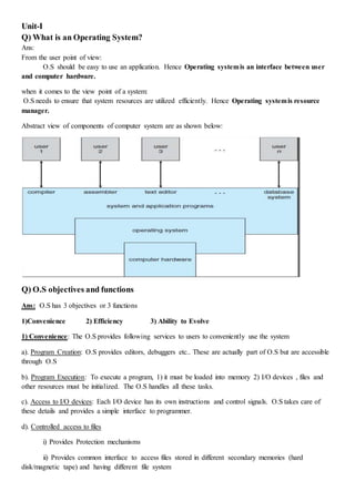
  • 1. Unit-I Q) What is an Operating System? Ans: From the user point of view: O.S should be easy to use an application. Hence Operating systemis an interface between user and computer hardware. when it comes to the view point of a system: O.S needs to ensure that system resources are utilized efficiently. Hence Operating systemis resource manager. Abstract view of components of computer system are as shown below: Q) O.S objectives and functions Ans: O.S has 3 objectives or 3 functions 1)Convenience 2) Efficiency 3) Ability to Evolve 1) Convenience: The O.S provides following services to users to conveniently use the system a). Program Creation: O.S provides editors, debuggers etc.. These are actually part of O.S but are accessible through O.S b). Program Execution: To execute a program, 1) it must be loaded into memory 2) I/O devices , files and other resources must be initialized. The O.S handles all these tasks. c). Access to I/O devices: Each I/O device has its own instructions and control signals. O.S takes care of these details and provides a simple interface to programmer. d). Controlled access to files i) Provides Protection mechanisms ii) Provides common interface to access files stored in different secondary memories (hard disk/magnetic tape) and having different file system
  • 2. e). System access: protects data and resources from unauthorized users. Resolves conflicts in case of contention for resources. f). Error detection and response: Many internal and external hardware errors , software errors occur while a computer is running. The O.S handles these errors by ending the program, retrying the operation that caused error or prints the error message to user. g). Accounting: O.S. collects usage statistics of various resources for improving performance and future enhancements 2) Efficiency: O.S decides how much processor time is to be given to a process, which processes must be in main memory, when an I/O device can be used by process, controls access to use of files etc.. efficiently. O.S manages the resources like CPU, memory, I/O devices, Secondary memory efficiently. Only part of O.S (called Kernel) is loaded into main memory and the rest of O.S will be in hard disk. CPU executes O.S code which directs the CPU which process to execute. Once the process is executed, CPU again runs the O.S code to know what to do next. 3. Ability to evolve: O.S will evolve due to following reasons i) Hardware upgrades and new types of hardware ii) New Services iii) Bug Fixes Q) Evolution of O.S Ans: Serial Processing (1940 – mid 1950) There was no O.S. User directly interacted with computer hardware. Single user system. Input and Output : Paper tape or punched cards Software Used: Assemblers, compilers, linkers, loaders, device drivers, libraries of common subroutines. Main Disadvantages: Low CPU utilization, high setup time. 1) Simple batch system 1. User do not have direct access to machine. 2. Monitor controls job processing: Special cards( that start with $ sign) indicate what to do. User program is prevented from performing I/O.
  • 3. 3. Resident Monitor (is part of monitor that always reside in memory) holds initial control, control transfers to job and then back to monitor 4. Automatic job sequencing is done as follows:  User submits job to computer operator. Computer operator batches the job sequentially and places the entire job on an Input device (Ex: card reader)  Monitor reads one job at a time from i/p device and places current job in User program Area.  Control is then passed to current job  When the job is completed, control return back to monitor. 5. Monitor handles job setup and reduces setup time by batching jobs with similar requirements  Job Control Language (JCL) instructions are given to monitor to execute the job.  Monitor reads $FTN card and loads the appropriate compiler from tape.  During execution of user program, any input instruction causes one data card to be read.  After successful or unsuccessful completion of user job, monitor will scan all i/p cards until it encounters next JCL card. Hardware features desirable in Batch system 1. Memory protection 2. Timer 3. Privileged Instruction 4. Interrupts 2) Multi-programmed Batch System : memory layout is as shown below If there is enough main memory to hold O.S and two programs, When one job needs to wait for I/O the CPU can switch to other job. This is known as multi programming or multi tasking. Additional hardware desirable are 1. Interrupt driven I/O and Direct Memory Access (DMA) 2. Memory management: Since several jobs must be in main memory at same time, some form of memory management is required. 3) Time sharing Systemare multi-programming systems and can handle interactive jobs. O.S gives quantum of CPU time to each user program. If ‘n’ users are there, each user is given 1/n of CPU time Problems to be handled in time sharing system 1. Since multiple jobs are in memory, they must be protected from modifying each other’s data. 2. File System must be protected by giving access to only authorized users. 3. Contention for resources must be handled. Q) Difference between Batch Multi-programming and Time sharing Batch Multi-programming Time sharing Principal Objective Maximize processor use Minimize response time Source of instructions to O.S JCL instructions provided with job Commands entered at terminal
  • 4. ================================================================= == Unit-II Q) What is process? A process is program in execution. A process is an active entity and resides in main memory. Q) Explain structure of process in memory A process contains 1. program code which is sometimes known as text section 2. Process stack: contains temporary data (Such as function parameters, return addresses and local variables) 3. Heap: is the memory allocated dynamically during process run time 4. Data section: contains global variables. Although two processes are associated with the same program, they are considered as two separate execution sequences as the data, heap and stack sections differ even though text sections are equivalent Q) Explain Process states As a process executes, it changes state. Each process can be in one of the following states 1. New: the process is being created. 2. Running: Instructions are being executed 3. Waiting: a process is waiting for some event to occur (such as I/O completion etc..) 4. Ready: process is waiting to be assigned to processor 5. Terminated: the process has finished execution. Q) What is PCB? Each process is represented in the operating system by a process control block (PCB) or task control block. It contains information about 1. Process state: the state may be new, ready, running, blocked or terminated. 2. Program Counter : this register stores the address of next instruction to be executed. 3. CPU registers: like accumulators, stack pointers, index register and general purpose registers. The values of these registers are saved if the process is interrupted. 4. CPU scheduling information : like process priority, scheduling parameters etc. 5. Memory management information : include the values of base and limit register, segment tables, page tables etc 6. Accounting Information: include amount of CPU used, time limits, job or process number etc. 7. I/O status information : like list of I/O devices allocated to the process, list of open files, and so on. Q)Operations on Processes 1. Process Creation
  • 5. Operating System is responsible for creation of new process. Reasons for a new process creation 1. When a batch job is submitted by user 2. In interactive environment or in time sharing system, a process is created when user logs on 3. Operating system creates a process to manage printing. So that user need not wait till printing completes. Here O.S creates process on behalf of user 4. When a process creates another process. Creating process is called parent process and new process is called child process or sub process. New process can in turn create other processes forming a tree of processes O.S identifies a process by unique process identifier (or pid) which is an unique integer. In solaris Operating system, at the top of the tree is Sched process with pid=0 . This process can create several child processes. In the below figure, it creates three child processes. 1. Init process is the parent process for all user processes 2. Pageout process 3. Fsflush process Subprocess may obtain resources 1. Directly from O.S 2. Share some resources among several of its children 3. Parent process partitions its resources among its children Parent process may pass initialization data to child. For ex: name of the image file and name of the output device may be passed to a display process (child process) Parent process may execute 1. concurrently with the child 2. waits till some or all of the child process have terminated. Address space of child process may be 1. Duplicate copy of parent (Same program and data) 2. New program loaded into it 2. Process Termination A process terminates when it finishes executing its final statement and requests the operating system to delete it (using exit() system call in Unix and Terminate Process() in Win32 API) All the resources of the process (open files, I/O buffers and physical memory) are deallocated by O.S A parent may terminate a child process for a variety of reasons 1. Child has exceeded its usage of some of the resources. 2. Task assigned to child is no longer required. 3. Parent is terminating and O.S (Ex: VMS) does not allow a child to continue if parent is terminating . Q) What is cascading termination Parent is terminating and O.S (Ex: VMS) does not allow a child to continue if parent is terminating. This is called Cascading Termination initiated by O.S
  • 6. Q) What happens to child when parent terminates in Unix? Init process becomes the parent of all its children Q)What is context switch? When the PCB of the currently executing process is saved the operating system loads the PCB of the next process that has to be run on CPU. This is a heavy task and it takes a lot of time. Q) Basic Concepts ofthreads A thread consists of a program counter, a stack, and a set of registers, and a thread ID. Threads are also called light weight processes. A process with multiple threads make a great server. The threads share a lot of resources with other threads belonging to the same process. So a context switch among threads for the same process is easy. It involves switch of register set, the program counter and the stack. Q) Explain two modes of CPU execution Protection of memory, I/O can be provided via two modes of CPU execution: user mode and kernel mode In kernel / privileged / supervisor mode, O.S has access to privileged instructions. Privileged instructions can access I/O devices, control interrupts, manipulate memory (pagetable, TLB, etc.). Privileged instructions are instruction that can only be executed in kernel mode. All the user level processes run in user mode. Some critical operations are not allowed to be done by user processes. The user processes must use systemcalls to perform these operations. When a system call occurs, O.S will enter into kernel mode and accesses privileged instructions to perform the desired service to user- level process. For example, for Input or Output, process makes a system call telling the operating system to read or write particular area and this request is satisfied by the operating system. Q) Explain Inter process communication. Ans: Cooperating processes require inter process communication (IPC) mechanism to exchange data and information. There are two communication models: (a) Message passing (b) shared memory as shown below. (a) Shared – Memory Systems: 1) Communicating processes must establish a region of shared memory. 2) Shared memory region resides in address space of the creating process.
  • 7. 3) Other processes that wish to communicate using shared memory segment must attach the shared memory to their address space. 4) Processes can exchange information by reading and writing data in shared areas. 5) Shared memory systems are convenient to communicate. 6) Shared memory systems are faster and provides maximum speed as i) System calls are required only to establish shared memory regions ii) Once shared memory is established, all accesses are treated as routine memory access. No assistance of kernel is required. (b) Message passing systems 1. Are useful for exchanging smaller amounts of data. 2. Easy to implement for inter computer communication 3. More time consuming than shared memory systemas implemented using system calls and need kernel intervention. To send messages, communication link must exist between them. Communication link can be physically or logically implemented. Different methods to logically implementing a link are 1. Direct or indirect communication 2. Synchronous or asynchronous communication 3. Automatic or explicit buffering 1a. Direct communication A link is established automatically between every pair of processes that want to communicate. A link is associated with exactly two processes. Addressing i) Symmetry in addressing: Sender process and receiver process must name each other to communicate. Send() and Receive() primitives are as follows: Send(P, message) –sends a message to process P Receive (Q, message) – receive a message from process Q ii) Asymmetry in addressing: Only sender names the receiver process. Send() and Receive() primitives are as follows: Send(P, message) –sends a message to process P Receive (id, message) – receive a message from any process Disadvantage of both types of addressing is limited modularity as changing the id of a process requires to find all the references to old id and then modify them 1b. Indirect communication 1. Messages are sent/ received to/from Mailboxes or ports 2. Each mailbox has unique id (integer value).
  • 8. P1 P2 2  R1  3. Two processes can communicate only if the process have a shared mailbox. 4. A link is established between two processes if they have a shared mailbox. 5. A link may be associated with more than two processes. 6. Mailbox may owned by process or O.S a. If mailbox is owned by process, we can distinguish between the owner( can receive messages only) and user(can send messages only). When the processes that owns a mailbox terminates, the mailbox disappears. b. If mailbox is owned by O.S, O.S must provide mechanisms to i. Create a new mailbox ii. Send and receive messages through mailboxes iii. Delete the mailbox iv. Pass ownership to other processes. 2. Synchronous or asynchronous communication Message passing may be either blocking(synchronous) or non-blocking(Asynchronous) 1. Blocking Send: The sending process is blocked until the message is received by the receiving process or mailbox. 2. Nonblocking Send: The sending process sends the message and resumes operation. 3. Blocking Receive: The receiver blocks until message is available 4. Nonblocking receive: The receiver retrieves either a valid message or a null. 3. Automatic or explicit buffering Messages exchanged by communicating processes reside in temporary queue. Such queues can be implemented in 3 ways i. Zero Capacity: Queue length =0 .. the link cannot have messages waiting in it..sender must block until receiver receives the message ii. Bounded Capacity: Queue length = finite (say n). When the queue is full, the sender must block until space is available in queue. iii. Unbounded Capacity: Queue length = infinite…the sender never blocks. ============================================================================= ==Q) what is deadlock? A set of processes is deadlocked when every process in the set is waiting for a resource that is currently allocated to another process in the set Here the processP1 isallocatedresource R2and P2 is allocatedR1. P1 requiresR1 andP2 requiresR2 ProcessP1 and P2 will waitforever.Thissituationis calleddeadlock. Q) What are the four conditions that are necessary for deadlock to occur : 1. Mutual Exclusion - At least one resource must be held in a non-sharable mode; If any other process requests this resource, then that process must wait for the resource to be released. 2. Hold and Wait - A process must be simultaneously holding at least one resource and waiting for at least one resource that is currently being held by some other process.
  • 9. 3. No preemption - Once a process is holding a resource, then that resource cannot be taken away from that process until the process releases it. 4. Circular Wait - A set of processes { P0, P1, P2, . . ., PN } must exist such that every P[ i ] is waiting for P[ ( i + 1 ) % ( N + 1 ) ]. Q)Methods for handling deadlocks 1. By using deadlock prevention and avoidance protocols, system will never enter a deadlocked state. 1. Allow the system to enter a deadlocked state, detect it and recover it. 2. Ignore the problem and pretend that deadlock never occurs. To make sure that the system must not enter a deadlocked state, the system can use 1. Deadlock prevention 2. Deadlock avoidance ============================================================================ == Deadlock Prevention 1. Mutual Exclusion: We cannot prevent deadlocks by denying the mutual exclusion condition, because some resources are nonsharable. (Ex: Printer) 2. Hold and Wait: To make sure that the hold-and-wait condition never occurs in the system, two protocols that can be used are Protocol 1: All the resources requested must be allocated before process begins execution. Protocol2: A process can request resources only when it has none. If a process requires additional resources, it must release all the resources that are currently allocated. Example: Consider a process that copies data from DVD drive to a file on disk, sorts the file and then prints the results to a printer. If Protocol1 is used, it must request the DVD drive, disk file and printer at the beginning and must hold them till the end. Disadvantages: 1. Starvation: A process may wait forever, because at least one resource that is need is always allocated to some other process. Hence Starvation is possible. 2. Resource Utilization is low: Process will hold the printer from beginning till end, even though it is used at the end. If Protocol 2 is used, the process will initially request DVD drive and disk file. It copies from the DVD drive to disk and then releases both the DVD drive and disk file. It then requests the disk file and printer. Disadvantage: There may be a chance that our data may not remain on the disk file. 3. No pre-emption To make sure that this condition does not hold, the following protocol is used.
  • 10. Protocol : If a process (say A) requests some resources Case 1: If resources are available then Allocate them. Case 2: if resources are allocated to some other process(say B) that is waiting for additional resources then Preempt the desired resources from the waiting process (B) and allocate them to requesting process(A). The process B can be restarted only when it is allocated additional resources it is requesting and takes away the resources that were given to process A. Case 3: if resources are neither available nor held by a waiting process then Process A waits This protocol is applied to resources like CPU register and memory space as the state of the resources can be saved. 4. Circular Wait: To make sure Circular Wait condition never occurs, 1. Each Resource is assigned a unique integer number 2. Each Process must request resources in an increasing order of enumeration. We define a one-to-one function 𝐹: 𝑅 → 𝑁, where R is the set of resource types and 𝑁 is the set of natural numbers. A process has requested a resource type say 𝑅𝑖 at the beginning. Protocol 1: After that, the process can request resource type 𝑅𝑗 if and only if 𝐹(𝑅 𝑗) > 𝐹(𝑅𝑖) Protocol 2: If a process requests a resource type 𝑅𝑗 , it must release all the resources (say (𝑅𝑖) ) whose 𝐹(𝑅𝑖) ≥ 𝐹(𝑅𝑗). Example : Let 𝐹(𝑡𝑎𝑝𝑒 𝑑𝑟𝑖𝑣𝑒) =1 F(disk drive) = 5 and F(printer)=12 A process can request any number of tape drives, disk drives and printers. Protocol 1: If a process A has already requested disk drive, now A can request only printer and cannot request tape drive. Protocol2: In order to request tape drive, the process A must release the disk drive and then can request tape drive. If the above two protocols are used, then the circular wait condition never occurs. We can prove this by contradiction. Proof: Assume circular wait exists. Let the set of processes involved in the circular wait be { 𝑃0, 𝑃1, …… , 𝑃𝑛} where 𝑃0 is waiting for resource 𝑅0 which is held by 𝑃1 𝑃1 is allocated 𝑅0 and 𝑃1 is waiting for resource 𝑅1 which is held by 𝑃2 so, 𝐹(𝑅0) < 𝐹(𝑅1)
  • 11. P1 P2 R2R  R1  𝑃2 is allocated 𝑅1 and 𝑃2 is waiting for resource 𝑅2 which is held by 𝑃3 so, 𝐹(𝑅1) < 𝐹(𝑅2) . . 𝑃𝑛 is allocated 𝑅 𝑛−1 and 𝑃𝑛 is waiting for resource 𝑅 𝑛 which is held by 𝑃0 so, 𝐹(𝑅 𝑛) < 𝐹(𝑅0) Hence by transitivity 𝐹(𝑅0) < 𝐹(𝑅0). Hence our assumption that circular wait exists is FALSE. ============================================================================= ==Q) Resource Allocation graph Deadlocks can be understood more clearly through the use of Resource-Allocation Graphs, having the following properties: 1. Resource Types are represented as square nodes on the graph. Dots inside the square nodes indicate number of resources. ( Ex: two dots might represent two laser printers. ) 2. Processes are represented as circles. 3. Request Edges - If P1 has requested R1, a directed edge from P1 to R1 is request edge 4. Assignment Edges - A directed edge from R2 to P1 indicating that resource R2 has been allocated to process P1, and that P1 is currently holding resource R2. Note that a request edge can be converted into an assignment edge when request is granted If a resource-allocation graph does contain cycles AND each resource contains only a single instance, then a deadlock exists. If a resource category contains more than one instance, then cycle in the resource-allocation graph indicates the possibility of a deadlock, but does not guarantee one. ================================================================= = Q) Deadlock Avoidance For each resource request, system can decide whether the request should be granted or not. To make this decision the system must have information like 1. resources currently available 2. resources currently allocated to each process. 3. Future requests and releases of each process 4. Maximum number of resources it may need. Given this information, it is possible to construct an algorithm that makes sure that the system will never enter a deadlocked state. There are Two deadlock-avoidance algorithms. They are 1. Resource-Allocation Graph Algorithm 2. Banker's Algorithm Safe State: A system is in safe state if there exists a safe sequence of processes { P0, P1, P2, ..., PN } such that Resource Requests for Pi <= Resources allocated to Pi + resources held by all processes Pj where j < i. All safe states are deadlock free
  • 12. Unsafe state : If a safe sequence does not exist, then the system is in an unsafe state, which MAY lead to deadlock. 1. Resource-Allocation Graph Algorithm  Resource-allocation graphs can detect deadlocks only if number of resources of each type are one  In this case, unsafe states can be recognized and avoided by adding claim edges, denoted by dashed lines, which point from a process to a resource that it may request in the future.  All the claim edges are added only at the beginning of process.  When a process makes a request, the claim edge Pi->Rj is converted to a request edge.  When a resource is released, the assignment edge changes back to a claim edge.  This approach works by denying requests that would produce cycles in the resource-allocation graph, taking claim edges into effect. Consider for example the resource allocation graph as shown If P2 requests resource R2 then the claim edge from P1->R2 will be made request edge as follows The resulting resource-allocation graph would have a cycle in it, and so the request cannot be granted. Q) Banker’s Algorithm or Deadlock avoidance algorithm with example. There are 12 tape drives let the current state of the system is as shown in the below figure Process Allocated Max Need Need= MaxNeed – Allocated P0 5 10 5 P1 2 4 2 P2 2 9 7 Available = 12-(5+2+2) = 3 Resource- Request Algorithm Now when a request for 1 tape drive by process P2 is made, we run resource-request algorithm to check whether the request must be granted or not. The request is granted if the after granting the request, all the processes in the system can complete. For that We check 1. Is the request of P2 <= need of P2 1 <= 7 therefore TRUE 2. Is the request of P2 <= Available
  • 13. 1 <= 3 therefore TRUE 3. Pretend the request is granted for P2. Now the current state is as shown below Process Allocated Max Need Need= MaxNeed – Allocated P0 5 10 5 P1 2 4 2 P2 2+1=3 9 7-1=6 Available = 3-1= 2 Now Run the safety algorithm to check whether the system is in safe state. Safety Algorithm 1. Let WORK = Available = 2 2. Find unfinished process such that Need of unfinished process <= WORK Check P0 Need of P0 = 5 Work = 2 Is 5 <= 2 ...FALSE Check P1 Need of P1 = 2 Work = 2 Is 2 <= 2...TRUE Therefore P1 can finish If P1 finishes ...Work = Work+Allocated to P1 Work=2+2= 4 Now again check if P0 can complete Need of P0 = 5 Work =4 Is 5 <=4 ..FALSE Check if P3 completes Need of P3= 6 Work =4 Is 6<= 4..FALSE So neither P0 can complete and P3 can complete...So the system is in unsafe state... The request for 1 tape drive by P3 is not granted. 2. Banker's Algorithm  For resources that contain more than one instance the resource-allocation graph method does not work. So we use Banker’s algorithm  When a process starts up, it must state in advance the maximum allocation of resources it may request  When a request is made, the scheduler determines whether granting the request would leave the system in a safe state. If not, then the process must wait until the request can be granted safely.  The banker's algorithm relies on several key data structures: ( where n is the number of processes and m is the number of resource categories. )
  • 14. o Available[ m ] indicates how many resources are currently available o Max[ n ][ m ] indicates the maximum demand of each process of each resource. o Allocation[ n ][ m ] indicates the number of each resources allocated to each process. o Need[ n ][ m ] indicates the remaining resources needed of each type for each process. ( Note that Need[ i ][ j ] = Max[ i ][ j ] - Allocation[ i ][ j ] for all i, j. )  For simplification of discussions, we make the following notations / observations: o One row of the Need vector, Need[ i ], can be treated as a vector corresponding to the needs of process i, and similarly for Allocation and Max. Safety Algorithm  In order to apply the Banker's algorithm, we first need an algorithm for determining whether or not a particular state is safe.  This algorithm determines if the current state of a system is safe, according to the following steps: 1. Let Work and Finish be vectors of length m and n respectively.  Work is a working copy of the available resources  Finish is a vector of booleans indicating whether a particular process can finish.  Initialize Work = Available, and Finish to false for all elements. 2. Find an i such that both (A) Finish[ i ] == false, and (B) Need[ i ] < Work. This process has not finished, but could with the given available working set. If no such i exists, go to step 4. 3. Set Work = Work + Allocation[ i ], and set Finish[ i ] to true. This corresponds to process i finishing up and releasing its resources back into the work pool. Then loop back to step 2. 4. If finish[ i ] == true for all i, then the state is a safe state, because a safe sequence has been found. Resource-Request Algorithm ( The Bankers Algorithm )  Now we have a tool for determining if a particular state is safe or not.  This algorithm determines if a new request is safe, and grants it only if it is safe to do so.  When a request is made ( that does not exceed currently available resources ), pretend it has been granted, and then see if the resulting state is a safe one. If so, grant the request, and if not, deny the request, as follows: 1. Let Request[ n ][ m ] indicate the number of resources of each type currently requested by processes. If Request[ i ] > Need[ i ] for any process i, raise an error condition. 2. If Request[ i ] > Available for any process i, then that process must wait for resources to become available. else the process can continue to step 3. 3. Check to see if the request can be granted safely, by pretending it has been granted and then seeing if the resulting state is safe. If resulting state is safe, grant the request else
  • 15. then the process must wait until its request can be granted safely. The procedure for granting a request ( or pretending to for testing purposes ) is:  Available = Available - Request  Allocation = Allocation + Request  Need = Need - Request Unit III Memory management Just as processes share the CPU, they also share physical memory. Memory management unit of OS takes care of memory allocation, deallocation, and other issues. Program must be brought into memory for it to be run. Addresses are two types i) relocatable or relative address w.r.t to the beginning of program ii) Absolute addresses Q)Address Binding Ans: Binding means mapping logical address space to physical address space. Address binding can happen at three different stages: Compile time: If you know at compile time only where in memory the program is going to be allocated, then compiler generates absolute addresses. Otherwise compiler generates relocatable addresses. Load time: loader binds the relocatable addresses generated by compiler to absolute address. Hence binding is done at load time If Binding is done at compile and load time, physical and logical addresses are same Execution time: If address binding is done at run time, the process can be moved during its execution from one memory segment to another. . Here we call logical addresses as virtual address. Run time mapping of virtual to physical address is done by a hardware device called Memory Management Unit (MMU) Q)Logical vs. Physical Address Space Ans:. Logical address – generated by the CPU; also referred to as virtual address Physical address – address seen by the memory unit. Set of all logical addresses is called logical address space. Set of all physical addresses is called physical address space. Q) Memory-Management Unit (MMU) Ans: MMU is hardware device that maps virtual to physical address. In MMU scheme, the value in the relocation register is added to every address generated by CPU to read the contents of memory The user program only knows logical addresses; it never sees the real physical addresses. Q)Dynamic loading Ans: Since physical memory is small, it may not be possible for the entire program to be in main memory, so we can use dynamic loading. It is responsibility of users to design their programs to take advantage of dynamic loading.
  • 16. Only the main function is loaded into main memory and when main() calls another function, the main() will check whether the function is in main memory. IF not, the loader will load the desired function to main memory and updates the program’s address table. Routine is not loaded until it is called. We achieve better memory-space utilization as unused routine is never loaded. Q) Dynamic Linking + Linking postponed until execution time. + Small piece of code, stub, used to locate the appropriate memory-resident library routine. + Stub replaces itself with the address of the routine, and executes the routine. + Operating system needed to check if routine is in processes’ memory address. + Dynamic linking is particularly useful for libraries. Q) Overlays Ans: Overlays are needed when process is larger than amount of main memory allocated to it. Instructions and data that are needed at any given time is kept in main memory. Overlays can be implemented by user. Programming design of overlay structure is complex. Overlays for a two-pass assembler is as shown in the figure. Q) Swapping Ans: A process can be swapped temporarily out of memory to a backing store and then brought back into memory for continued execution. Backing store – fast disk large enough to store copies of all memory images of all users Priority based scheduling uses a variant of swapping policy called roll out , roll in. If a higher priority process arrives, the memory manager swaps out lower priority process and then swaps in higher priority process. When the higher priority process finishes, the lower priority process can be swapped in again to main memory. A process that is swapped out will be swapped back into the same memory space it occupied previously. Major part of the swap time is transfer time. We can swap idle process only and cannot swap a process that is waiting for I/O Q) Contiguous memory allocation: Ans: Each process is contained in a single contiguous section of memory. 1. Fixed Size Partition (or) Single-partition allocation Divide the main memory into Fixed sized partitions. Each partition may contain exactly one process. Relocation register contains value of starting physical address; Limit register contains range of logical addresses. Every address generated by a CPU is checked as follows If logical address < Limit register then logical address is added with Relocation register to get the corresponding memory address. else a trap to O.S is generated.
  • 17. Since every address is checked, we can protect the O.S and other user programs from being modified by other running process. 2. Multiple-partition allocation 1) Fixed Size Partitions: Divide the main memory into Fixed sized blocks Here memory allocated to a process may be larger than required. The difference between allocated memory and requested memory is called internal fragmentation. Internal fragmentation is unused memory inside the partition. if P1 requires just 5 addresses still it is allocated 2 blocks i.e, 8 addresses. So remaining 3 addresses are left unused. 2) Variable Size partitions: Here main memory is divided into partitions of variable sizes. Operating system maintains information about: a) allocated partitions b) free partitions (hole) In the beginning, all main memory is empty and is considered one large block of available memory, a hole. Exact memory required by process is only given. When a process terminates, it releases memory, which can be allocated to another process. Memory is allocated to processes until , finally, no available block of memory (or hole) is large enough to hold the next process. External fragmentation exists when there is enough memory to satisfy a request but the available memory are not contiguous. Wastage of memory outside the partition One Solution to problem of external fragmentation is a. Compaction: shuffle the memory contents so as to place all free memory together into one large block. ============================================================================= == Q) Dynamic Storage-Allocation Problem (or) Most commonly used strategies to select a free hole from the set of available holes Ans: To satisfy a request of size n from a list of free holes, below 3 policies can be used 1. First-fit : Allocate the first hole that is big enough. 0 P1 Block0(0th address to 3rd address) 4 P1 Block1(4th address to 7th address) 8 Block2(8th address to 11th address) 12 Block3(11th address to 12th address)
  • 18. 2. Best-fit: Allocate the smallest hole that is big enough; must search entire list, if it is not ordered by size. Produces the smallest leftover hole. 3. Worst-fit: Allocate the largest hole; must also search entire list. Produces the largest leftover hole. First-fit and best-fit better than worst-fit in terms of speed and storage utilization. ============================================================================= ==Q) Non-Contiguous Memory allocation 1. Paging : Paging: is a memory management scheme that provides non-contiguous memory allocation. Logical address space of a process can be noncontiguous; Ex: P1 is allocated Block0 and Block3 1. Divide physical memory into fixed-sized blocks called frames (size is power of 2) 2. Divide logical memory into blocks of same size called pages. 3. Logical address is divided into 2 parts Page number (p) – Page table is indexed by page number. Page offset (d) – 4. A page table is allocated to each process. (A pointer to page table is stored in PCB of process. ) Page table translates logical to physical addresses. Page 0 is in frame1, Page 1 is in frame 4 etc.. 5. Internal fragmentation may occur due to paging. 0 P1 Block0(0th address to 3rd address) 4 P2 Block1(4th address to 7th address) 8 Block2(8th address to 11th address) 12 P1 Block3(11th address to 12th address)
  • 19. 6. If the size of logical address space= 2 𝑚 and page size = 2 𝑛 Then the higher order 𝑚 − 𝑛 bits of logical address correspond to page number and ‘n’lower order bits for displacement within the page. Ex: size of logical address space = 8=23 so, m=3 page size =4=22 So, n=2 So 𝑚 − 𝑛 = 1 bit for page number to represent 0,1 remaining n=2 bits for displacement within the page Q) Implementation of Page Table: Page table can be kept as 1) Set of dedicated registers: efficient if the page table is small 2) Page table can be kept in memory page table base register (PTBR) points to page table. Page-table length register (PTLR) indicates size of the page table. Changing page table requires changing only the value in these registers. Advantages of keeping page table in memory: a. Less context switch time b. Two memory accesses are required. One memory access to access the page table and another memory access to access the required memory address. This problem can be solved by using a special fast-lookup hardware cache called associative memory or translation look-aside buffers(TLBs) i. Each entry in TLB consists of 2 parts
  • 20. I) page number field II) Value field or frame number field. ii. When a logical address is generated by CPU, its page number is presented to TLB. The page number is compared with all the entries of TLB simultaneously . If page number is found in TLB , It’s frame number is immediately available -> TLB hit If page number not found, check in page table –TLB miss By using TLB, Search is fast But TLB hardware is expensive. So TLB size is kept small. So TLB contains only frequently used few page table entries. Q) Protection in Paging : Valid/invalid bit attached to each entry in the page table. O.S sets this valid/invalid bit for each page to allow or disallow access to the page. When the bit is set to invalid, the page is not in process’s logical address space. Hence it generates Trap to O.S. Q) Shared pages in Paging: Reentrant code is the code that never changes during execution. Reentrant code can be shared 1. One copy of read-only (reentrant) code is shared among processes (i.e., text editors, compilers, window systems). Ex: ed1,ed2,ed3 is shared among Process P1 and P2. 2. Shared code must appear in same location in the logical address space of all processes. Each process keeps a separate copy of the private code and data. EX: data1 and data2
  • 21. The pages for the private code and data can appear anywhere in the logical address space. ============================================================================ ==Q) Segmentation Segmentation is a memory management scheme that support user’s view of memory. When the user program is compiled, the compiler generates segments like 1) The code segment 2) Global variables segment 3) Heap memory segment 4) Stack segment etc.. Each entry in segment table has  segment base (Starting physical address of segment) and  limit register (specifies the length of the segment). Logical address is divided into 2 parts.  segment-number,  offset Segment table is indexed by segment number. Segment-table base register (STBR) stores the location of segment table in main memory. Segment-table length register (STLR) stores number of segments used by a program. The segment number (say ‘s’) is used to find the entry in segment table. The required entry is ‘s’ locations away from the beginning of the segment table. Once the required entry in the segment table is found, the offset (‘d’) is compared with limit. If( offset < limit) then offset is added with the base entry to generate the physical address. Q) Shared Segments
  • 22.  Code sharing occurs at the segment level.  Shared segments must have same segment number.  Allocation - dynamic storage allocation problem  use best fit/first fit, may cause external fragmentation.  Protection  protection bits associated with segments  read/write/execute privileges  array in a separate segment - hardware can check for illegal array indexes. ============================================================================= == Q) Virtual memory – Ans: In paging and segmentation, a program will execute only if the entire process is in main memory. But here in virtual memory, only part of the program needs to be in memory for execution 1. A program that is large enough than the available main memory can still run as only part of program is only loaded into main memory. Logical address space can therefore be much larger than physical address space 2. Allows address spaces to be shared by several processes Virtual memory can be implemented via:  Demand paging  Demand segmentation The large blank space between heap and stack is part of virtual address space. Virtual memory allows files and memory to be shared by 2 or more processes through page sharing as shown in below figure (b). Figure (a) depicts that virtual memory that is larger than physical memory
  • 23. ============================================================================ == Q)Demand paging Demand paging is technique of loading pages from disk to main memory only when the page is needed. Hence using less amount of physical memory we get faster response. Demand paging is similar to PAGING + SWAPPING Instead of swapping a whole process, the pager brings only those pages needed into memory. To distinguish between pages that are in memory and pages that are on the disk, valid/invalid bit is used. Valid/invalid bit is attached to each entry in page table. When this bit is set to valid, the page is legal and in memory. When this bit is set to invalid, either the page is illegal or the page is in disk. When CPU generates a logical address whose page table entry is set to invalid, page fault occurs. Hence the required page is in disk. Some section of hard disk called swap space is used to hold pages that are not present in memory. Q) Procedure for Handling a Page Fault 1) CPU generates a logical address and if the valid/invalid bit for the page that has this logical address is set to invalid, page fault occurs. 2) Page fault causes a trap to operating system. 3)Check if the logical address is within the logical address space of process. i.e. PTBR and PTLR is checked. if (required logical address is not within the logical address space of process.) Terminate the process else page is not in memory and page is in disk.
  • 24. 4) To bring the required page into memory, we need to find a free main memory frame, map main memory address to disk block and fetch disk block and load the block into free frame. 5) When the required page is brought into memory, update the page table to indicate the page is in memory. 6) Restart instruction interrupted by illegal address trap. The process will continue as if page had always been in memory. Q) What is pure demand paging Ans: If no page belonging to the executing process is in main memory, the process will fault for every page it needs. Page faults will occur until every page that is needed is in memory. This scheme is known as pure demand paging: NEVER BRING A PAGE UNTIL IT IS REQUIRED. Q) Page Replacement 1. Find the location of the desired page on the disk. 2. Find a free i) If there is a free frame, use it. ii) If there is no free frame, use Page replacement Algorithms to find some page in memory that is not really in use and swap it. iii) If the modify bit associated with the victim frame is set to 1, the page is written to disk. Make the changes to valid/invalid bit of victim frame's page table entry to invalid to indicate the victim frame is no longer in memory. else no need to write to disk 3. Read the desired page into victim frame and change the frame and page tables. 4. Restart the user process. =============================================================================================== == Q) Page Replacement Algorithms Goal: Produce a low page-fault rate. The algorithms are evaluated by running it on a particular string of memory references (reference string) and by computing the number of page faults on that string. 1. First in First out (FIFO) Page replacement algorithm: Uses the time when a page was brought into memory. The page that was brought first into memory is replaced i.e, oldest page is chosen for replacement. We create a FIFO queue to hold all pages in memory. When a page is brought into memory, we insert it at the tail of the queue and we replace the page at the head of the queue.
  • 25. FIFO: 15 page faults Problems due to FIFO is Belady’s anamoly. For a refrence string shown below 1,2,3,4,1,2,5,1,2,3,4,5 When number of frames allocated to a process is 1, number of page faults=12 due to FIFO page replacement When number of frames allocated to a process is 2, number of page faults=12 due to FIFO page replacement When number of frames allocated to a process is 3, number of page faults=9 due to FIFO page replacement When number of frames allocated to a process is 1, number of page faults=10 due to FIFO page replacement As the number of frames allocated to a process increases, page faults must decrease. But in FIFO page replacement, page faults increase. 2. Optimal Page replacement Algorithm Replace the page that will not be used for longest period of time. Used for measuring how well your algorithm performs. It is not practical to implement OPT algorithm as it is not possible to know what the future references will be ex: Optimal page replacement: 9 page faults. 3. Least Recently used (LRU) Page replacement algorithm: Replace the page that has not been used for longest period of time. LRU makes use of time of last use of the page. Ex: Number of page faults = 12 LRU requires hardware assistance to determine the time of last use of the page. We can use 1) Stack or 2) Counter to implement LRU page replacement algorithm. 1) Stack implementation – keep a stack of page numbers in a double link form: when a Page is referenced, it is moved to the top of stack This implementation requires 6 pointers to be changed. 2) counter implementation: Time-of-use field is allocated to each frame allocated. CPU maintains a counter. Counter is incremented for every page reference.
  • 26. Counter value is copied to the time-of-use field of the referenced page Disadvantages of LRU page replacement algorithm: Updating counter or stack must be done for every memory reference. HENCE LRU IS SLOW and implementation requires hardware assistance. ============================================================================= = Q) LRU approximation page replacement 1) Using reference bit 2) Using additional reference bits algorithm 3) Second chance algorithm 4) Enhanced Second chance algorithm 5) Counting based Page replacement Has two schemes 1) Least Frequently Used (LFU) 2) Most Frequently Used (MFU) 6) Page Buffering Algorithms Q) What is Thrashing Ans: A process is thrashing if it is spending more time paging than executing. Thrashing may occur when global (or) local page replacement is used as follows Solution to Thrashing is Working Set strategy If we provide a process with as many frames as it needs, thrashing can be avoided. Since it is not possible to know how many frames a process needs, we use locality model of process execution. here Locality is set of pages that are actively used together. Locality model states that as the process executes it moves from locality to locality. If we allocate enough frames to a process to accommodate the size of current locality, it will not fault again until it changes current locality. Working Set model uses working-set and a parameter ∆ = working-set window The set of pages in the most recent ∆ page references is the working set Let 𝑊𝑆𝑆𝑖 be the working-set size for process 𝑃𝑖 i.e, 𝑃𝑖 needs 𝑊𝑆𝑆𝑖 frames Let 𝐷 be the total demand for frames then 𝐷 = ∑ 𝑊𝑆𝑆𝑖 and 𝑚 be the total number of available frames If > 𝑚 , thrashing occurs because some processes will not have enough frames. So IF (𝐷 > 𝑚) O.S selects a process to suspend else O.S may initiate another process The working set strategy prevents thrashing while keeping the degree of multi programming as high as possible. The main difficulty is to keep track of moving working set window. ======================================================================== Q) How does thrashing occur in global and local page replacement Ans: In Global page replacement: when a page fault occurs for a process, any frame in main memory can be replaced causing page fault to some other process that needs the replaced frame. Page fault processes must use paging device to swap pages in and out. As more number of processes queue up for the paging device, the READY queue empties. And CPU becomes idle. So, O.S introduces new processes as CPU is free. This further increases number of page faults.
  • 27. In Local page replacement: Each process is allocated certain frames in main memory and when a page fault occurs, only the frames allocated to it will be replaced. When a process starts thrashing, other processes are not affected. But since the processes will be in queue for paging device most of the time, average service time for page fault increases. Hence effective access time will increase even for a process that is not thrashing. Q) Page Table Structure Or Structure of page table in memory  Hierarchical Paging  Hashed Page Tables  Inverted Page Tables  Hierarchical Paging If Page table is large then we break up the page table into multiple page tables i.e, page table is paged. A simple technique is a two-level page table. Two-Level Paging Example : A logical address (on 32-bit machine with 4K page size) is divided into: 1. a page number consisting of 20 bits. 2. a page offset consisting of 12 bits. Since the page table is paged, the page number is further divided into: 1. a 10-bit page number. 2. a 10-bit page offset. Thus, a logical address is as follows: page number page offset pi p2 d 10 10 12 where p1 is an index into the outer page table, and p2 is the displacement within the page of the outer page table. Two-Level Page-Table Scheme Address-Translation Scheme Address-translation scheme for a two-level 32-bit paging architecture
  • 28.  Hashed Page Tables (or) Hash table Hashed page tables are common in address spaces > 32 bits. Each entry in hash table contains a linked list of elements that hash to same location Hash table is indexed by hash value Each element consists of 3 fields 1. Page number 2. Frame number 3. Pointer to next element in linked list. The algorithm works as follows  Page number is passed to hash function to get hash value.  Locating the hash value in hash table is easy as Hash table is indexed by hash value  Page number is then compared with field 1 in the first element in linked list  If there is a match, the corresponding frame number is used to get physical address  If there is no match, next entries in linked list are searched  Inverted Page Table Invertible page table has one entry for each frame of physical memory. Each entry in invertible page table has  Process-id  Page number Logical address also has 3 parts  Process-id
  • 29.  Page number  Offset Process-id and page number of the logical address is compared with each entry in the invertible page table. If a match is found at ith entry, i is added to offset to get logical address. If there is no match, it means it is illegal address. Advantages and disadvantages:  Decreases memory needed to store each page table  Increases time needed to search the table when a page reference occurs. Solution: Use hash table to limit the search to one — or at most a few — page-table entries. Inverted Page Table Architecture Unit-IV CPU Scheduling Basic concepts To maximize CPU utilization, some process must be running at all times. In multi programming, several processes will be in main memory at a given time. If running process has to wait for I/O, the O.S takes the CPU away from that process and assigns CPU to other process in ready queue. So CPU must be scheduled and CPU scheduling is fundamental O.S function CPU- I/O burst cycle Process execution begins with a CPU burst that is followed by an I/O burst, which is followed by another CPU burst then another I/O burst and so on as shown in the figure An I/O bound program has many short CPU bursts. A CPU-bound program has few long CPU bursts Schedulers: a module in OS for scheduling decisions. � Long-term scheduler (or job scheduler) – selects which processes should be brought into the ready queue � Medium-term scheduler – selects which processes should be swapped in/out the memory � Short-term scheduler (or CPU scheduler) – Whenever the CPU becomes idle, the operating system must select one of the processes in ready queue to be executed. This selection is done by short term scheduler (or) CPU scheduler.
  • 30. Dispatcher: gives CPU control to the process selected by short term scheduler. This function involves following 1. switching context 2. switching to user mode 3. jumping to proper location in the user program to restart that program Time taken to stop one process and start another process is known as dispatch latency. This must be kept small. Ready Queue Ready queue is implemented as a FIFO queue, a priority queue, a tree or simply an unordered linked list. The records in ready queue are PCBs of processes. Pre-emptive Scheduling CPU scheduling decisions take place under one of four conditions: 1. When a process switches from the running state to the waiting state 2. When a process switches from the running state to the ready state, for example in response to an interrupt. 3. When a process switches from the waiting state to the ready state, say at completion of I/O 4. When a process terminates.  For conditions 1 and 4 there is no choice - A new process must be selected.  For conditions 2 and 3 there is a choice - continue running the current process (or) select a different one.  If CPU scheduling takes place only under conditions 1 and 4, the system is said to be non- preemptive, or cooperative. In non-preemptive, a process runs until it itself gives up the CPU i.e, when it is waiting for I/O (or) when process completes. Otherwise the system is said to be pre- emptive.  Windows used non-preemptive scheduling up to Windows 3.x, and started using pre-emptive scheduling with Win95. Macs used non-preemptive prior to OSX, and pre-emptive since then. Note that pre-emptive scheduling is only possible on hardware that supports a timer interrupt.  Note that pre-emptive scheduling can cause problems when two processes share data, because one process may get interrupted in the middle of updating shared data structures.  Preemption can also be a problem if the kernel is busy implementing a system call ( e.g. updating critical kernel data structures ) when the preemption occurs. Solution : wait until the system call has either completed or blocked before allowing the pre-emption. But this solution is problematic for real-time systems.  Some critical sections of code protect themselves from concurrency problems by disabling interrupts before entering the critical section and re-enabling interrupts on exiting the section. But this should only be done only on very short pieces of code that will take less CPU time. Scheduling Criteria to decide CPU scheduling algorithm 1. CPU utilization: in real system, cpu utilization will range from 40% to 90% 2. Throughput: Number of processes that are completed per unit time. 3. Turnaround time: Time when the process has completed – Time when the process was submitted i.e, it includes waiting time and burst time 4. Waiting time: amount of time that a process spends waiting for CPU 5. Response time: Time when the first response came - Time when the process was submitted Optimization Criteria Max CPU utilization
  • 31. Max throughput Min turnaround time Min waiting time Min response time CPU Scheduling Algorithms 1). First-Come, First-Served (FCFS) Scheduling: First come first served CPU scheduling algorithm is non pre-emptive Processes are scheduled in the order they have arrived. FCFS is implemented by Queue. When the CPU is free, it is allocated to the process at the head of the queue. Advantages: Easy to implement Disadvantages: 1. Average waiting time is quite long 2. Convoy effect (it occurs as small processes wait in queue for big process to leave CPU) Example: Suppose that the processes arrive in the order: P1 , P2 , P3 The Gantt Chart for the schedule is: P1 P2 P3 0 24 27 30 Waiting time for P1 = 0; P2 = 24; P3 = 27 Average waiting time: (0 + 24 + 27)/3 = 17 2). Shortest-Job-First (SJF) Scheduling Schedule the Process with shortest burst time. If CPU burst time of two processe are same then FCFS is used Advantages: Average waiting time decreases Disadvantages: It is difficult to know the length of next CPU burst. SJF can be either pre-emptive (or) non pre-emptive 1. Non pre-emptive SJF – once CPU is given to the process it cannot be preempted until completes its CPU burst. 2. Pre-emptive SJF (or) Shortest-Remaining-Time-First (SRTF). If the newly arrived process is shorter than what is remaining of currently executing process then pre-empt the currently executing process. Example: Process Arrival Time Burst Time P1 0.0 7 P2 2.0 4 P3 4.0 1 P4 5.0 4 SJF (non-preemptive) Gantt Chart P1 P3 P2 P4 0 7 8 12 16 Process Burst Time P1 24 P2 3 P3 3
  • 32. Average waiting time = [0 +(8-2)+(7-4) +(12-5)] /4 =4 Example of Preemptive SJF Process Arrival Time Burst Time P1 0.0 7 P2 2.0 4 P3 4.0 1 P4 5.0 4 SJF (preemptive) P1 P2 P3 P2 P4 P1 0 2 4 5 7 11 16 Average waiting time = (9 + 1 + 0 +2)/4 =3 3). Priority Scheduling A priority number (integer) is associated with each process The CPU is allocated to the process with the highest priority (smallest integer ≡ highest priority). If two processes have equal priority then FCFS is used SJF is a priority algorithm in which larger the CPU burst, lower the priority. There are two schemes. 1. Preemptive 2. nonpreemptive Problem ≡ Starvation – low priority processes may never execute. Solution ≡ Aging – as time progresses increase the priority of the process. 4). Round Robin (RR) Each process gets a small unit of CPU time (time quantum), usually 10-100 milliseconds. After this time has elapsed, the process is preempted and added to the end of the ready queue. If there are n processes in the ready queue and the time quantum is q, then each process gets 1/n of the CPU time in chunks of at most q time units at once. No process waits more than (n-1)q time units. Performance 1. q large _ FIFO 2. q small _ q must be large with respect to context switch, otherwise overhead is too high. Example of RR with Time Quantum = 4 Process Burst Time P1 24 P2 3 P3 3 The Gantt chart is:
  • 33. P1 P2 P3 P1 P1 P1 P1 P1 0 4 7 10 14 18 22 26 30 Average waiting time = [(30-24)+4+7]/3 = 17/3 =5.66 5)Multilevel Queue scheduling Ready queue is partitioned into separate queues: For ex: ready queue is divided into 2 queues 1. foreground (interactive) queue 2. background (batch) queue Each queue has its own scheduling algorithm, For ex: Round Robin scheduling algorithm can be used in foreground queue FCFS scheduling algorithm can be used in background queue Scheduling must be done between the queues. This can be done in 2 ways 1. Fixed priority scheduling Foreground queue has highest priority. All the processes in foreground queue must be completed and queue must be empty. Then only the processes in background queue will be given CPU. As shown in below figure. Disadvantage: starvation. 2. Time slice – each queue gets a certain amount of CPU time which it can schedule amongst its processes; i.e., 80% to foreground in RR and 20% to background in FCFS 6) Multilevel Feedback Queue Scheduling A process can move between queues. The idea is to separate processes according to their CPU bursts. I/O – bound and interactive processes will be in highest priority queue. If a process takes more CPU time, it is moved to lower priority queue. If a process waits too long in lower priority queue, it is moved to higher priority queue to prevent starvation. As shown in the below figure, let there be 3 queues Q0, Q1, Q2. 1. Q0 – time quantum 8 milliseconds 2. Q1 – time quantum 16 milliseconds 3. Q2 – FCFS Scheduling 1. A process entering ready queue is put in queue Q0 When it gains CPU, the process receives 8 msec.
  • 34. If it does not finish in 8 milliseconds, process is moved to queue Q1. 2. At Q1, process again receives 16 additional milliseconds. If it still does not complete, it is moved to queue Q2. Q) Synchronization Several processes run in an operating system. Some process share resources due to which problems like data inconsistency may arise. Example of process synchronization is Producer Consumer problem (or) Bounded-Buffer problem Producer Consumer problem: To make sure that producer process should not add data when the buffer is full and Consumer process should not take data when the buffer is empty The code for Producer process can be modified as follows: while (true) { /* Produce an item in next produced*/ while (counter == BUFFER_SIZE); /* do nothing*/ buffer[in]=nextProduced; in = (in+1)% BUFFER_SIZE counter++; } here an integer variable counter is initialized to zero. Counter is incremented every time a new item is added to the buffer and counter is decremented every time an item is removed from buffer. in is an index that always points to an empty slot after the last filled slot. out is an index that always points to the first filled slot after at the head of the circular queue. The code for consumer process is as shown below while(true) { while (counter == 0); /* do nothing*/ nextConsumed = buffer[out]; out=(out+1)%BUFFER_SIZE; counter--; } The above producer and consumer code produces RACE CONDITION Outcome of execution of several co-operating processes depends on the order in which accesses takes place is called Race Condition..For Example: if counter =5
  • 35. Given counter =5 and if producer produces one item and consumer consumes one item then correct value of counter= 5 only. But here the counter = 4 i.e, inconsistent result If T5 is executed before T4 then the counter =6 i.e, inconsistent result Solution to avoid race condition: make sure only one process at a time must update the shared variable (here it is counter). Q) Critical section problem Ans: Each process has a segment of code called critical section. Critical section code is the code that contains common variables of co-operating processes. To avoid data inconsistency Two processes must not execute critical section code at same time. For this to happen, 1. Each process must request permission to enter its critical section—Entry section 2. End of critical section –Exit section 3. Rest of the code after critical section – Remainder section Solution to critical section must satisfy the following three requirements 1. Mutual exclusion : if one process is in critical section , no other process can be in critical section 2. Progress: Processes not in remainder section must decide which process will enter critical section next. 3. Bounded Waiting: All the processes must be allowed to enter critical section. No process must wait indefinitely. Q) Peterson’s solution for critical section problem (Software based solution) Ans: Time Process 1 Process2 T0 do{ flag[1] = TRUE; turn =2; do{ flag[2] = TRUE; T1 turn =1; T2 While( flag[2] && turn == 2); Since turn != 2 while loop will not run. While( flag[1] && turn == 1); Loops continuously until flag[1] becomes false T3 Enter critical section
  • 36. T4 flag[1] = FALSE Enter Critical section T5 Enters remainder section flag[2]=FALSE } while (TRUE) Enters remainder section } while (TRUE)
  • 37. 10.1 File Concept: Data is stored in secondary memory in the form of files. A file is a sequence of bits, bytes, lines or records. A file has structure which depends on its type. File Attributes 1. Name – Name of the file for user understanding. 2. Identifier : used by O.S to identify a file ( e.g. inode number ) 3. Type – Text files, executable files, binary files, etc. 4. Location – location of the file on the hard drive. 5. Size: current size of the file. 6. Protection: Controls who can read, write or execute the file. 7. Time, Date and user identification: gives the information when the file was created, last modified and last used etc. This data is used for protection, security and usage monitoring. All information about files is kept in directory structure. The directory entry consists of the file’s name and its unique identifier. The identifier locates the other file attributes. Directory structure is kept on disk. File Operations The file Abstract Data Type supports many common operations: 1. Creating a file: find free space on disk, add entry to directory . 2. Writing a file: write data at current file position pointer location and update pointer. 3. Reading a file: read data at current file position pointer location and update pointer. 4. Repositioning within a file or file seek: change pointer location to a given value. 5. Deleting a file: free the space allocated to file and remove entry from directory 6. Truncating a file : delete the data and update file size. Open File Table  Most O.Ses require that files be opened before access and closed after access.  Information about all files that are open currently in the system is stored in an open file table. This systemwide open file table is maintained by O.S.  And information about files opened by the process is stored by the process’s open file table  Open file table has the following information. 1. File pointer - records the current position in the file, for the next read or write. 2. File-open count - How many times has the current file been opened ( simultaneously by different processes ) and not yet closed? When this counter reaches zero the file can be removed from the table. 3. Disk location of the file. 4. Access rights  Some systems provide support for file locking. 1. A shared lock is for reading only. 2. A exclusive lock is for writing as well as reading. 3. An advisory lock : O.S makes sure the locks are acquired and released appropriately 4. A mandatory lock : software developers makes sure the locks are acquired and released appropriately. 5. UNIX used advisory locks, and Windows uses mandatory locks.
  • 38. File Types: Implementing file types: A common technique is to include the type as part of the filename. The name is split into 2 parts: 1. File Name 2. Extension File name and extension are separated by a period. The system uses the extension to indicate the type of file and the type of operations that can be done on that file. User opens Microsoft word and clicks on File menu and Open option. User will only specify the filename without extension, application will look for a file with the given name and extension it expects. Hence extensions are not supported by the operating system. Unix system uses a crude magic number stored at the beginning of the file to indicate the type of file. In Mac O.S X operating system, file produced by word processor has the word processor’s name as its creator. When user double clicks on the file, word will open the required file. Some common file types are as shown below. File Structure  Some files contain an internal structure, which may or may not be known to the OS.  for ex: executable files have a specific structure so that it can determine where in memory to load the file and what is the location of the first instruction.  If O.S supports many file formats, it will increase the size and complexity of the OS.  UNIX treats all files as sequences of bytes, with no internal structure. (With the exception of executable binary programs, which it must know how to load and find the first executable statement, etc.)  Macintosh files have two forks - a resource fork, and a data fork. The resource fork contains information relating to the UI, such as icons and button images, and can be modified independently Data fork contains the code or data. Internal File structure  Disk files are accessed in units of physical blocks, typically 512 bytes
  • 39.  Internally files are organized in units of logical units like single byte (or) data record size (or) structure size.  The number of logical units which fit into one physical block determines its packing. If a student file is organized internally as records. Each record takes 64 bytes of memory. And main memory is divided into blocks of 512 bytes. Then packing = 512/64=8 .. 8 records can be stored per block.  Internal fragmentation may occur due to this. 10.2 Access Methods The information in file can be accessed in the following ways 1. Sequential access 2. Direct access (or) Relative access. 1. Sequential access: we cannot randomly access any record. Records are read and written sequentially one record after another. A sequential access file emulates magnetic tape operation and generally supports the following operations:  read next - read a record and advance the tape to the next position.  write next - write a record and advance the tape to the next position.  rewind  skip n records - May or may not be supported. N may be limited to positive numbers, or may be limited to +/- 1. 2. Direct access (or) Relative access: A file is made up of fixed length records so that we can randomly access any record. No restriction on order of reading or writing Direct access files are useful when we need to access large amounts of data randomly. Ex: database Operations supported include: n is relative block number i.e, relative to beginning of file. 1. read n - read record number n. 2. write n - write record number n. 3. jump to record n - could be 0 or the end of file. 4. Query current record - used to return back to this record later. 5. Sequential access can be easily emulated using direct access. The inverse is complicated and inefficient.
  • 40. 3. Other access methods can be built on top of direct access method. We construct an index for the file which contains pointers to various blocks. To search a file, we first access index and then use pointer to access file. If a student file has 1,20,000 records of students sorted by student id. We can create an index consisting of 1st student id in each block. if 64 records can be stored in each block, then number of blocks needed to store 1,20,000 records = 1,20,000/64 ≈ 2000 blocks. So index has 2000 entries. Index is kept in main memory so that searching becomes faster. If the index itself becomes large, we create an index for index file (Ex: B-tree) Q) Allocation Methods To allocate space to files on disk is such a way that disk space is utilized effectively and files can be accessed quickly. Three major methods of allocating disk space are 1. Contiguous 2. Linked
  • 41. 3. Indexed 1. Contiguous allocation: Each file occupies set of contiguous blocks on disk. If the file is n blocks long and starts at location b, then it occupies blocks b, b+1, b+2,….b+n-1. The directory entry for each file indicates the address of starting block(i.e, b) and length (n) Advantages: 1. For direct access to block i, we can directly access by finding the block as b+i Since the file is stored sequentially, sequential access is easy. Hence access is easy. 2. Supports both direct and sequential access 3. Number of disk seeks required is minimum. 4. Seek time is minimum. Disadvantages: 1. Difficult to find space to a new file (or) add more data to existing file First fit and Best fit strategies are used to find a free hole( set of free contiguous blocks) from list of available holes. But both are inefficient w.r.t storage utilization. 2. External fragmentation: even though there are enough free blocks required for a new file, they are not contiguous and hence cannot be allocated to new file. Solution : copy all the files onto another disk or tape. We then copy the files back onto original disk contiguously. This is known as compaction. But compaction is time consuming. 3. Size of the file must be known when the file is created. Even though final size is known, entire size may not be used by the file at the beginning. Hence leads to wastage of space. If size of the file is not known in advance then (i) If we allocate too little space to file, file cannot be extended. Solution: find a larger hole, copy the contents of the file to the new space and release the previous space. This may be possible as long as space exists. Also this is time consuming (ii) If we overestimate the amount of space needed, much of the space is unused. This will lead to internal fragmentation. To minimize these drawbacks , some o.s. uses modified contiguous allocation scheme. Here contiguous blocks of memory is allocated at first. If the file needs more blocks , another set of contiguous space known as extent is added. Location and a block count plus a link to the first block of next extent. If extents are too large and of fixed size, internal fragmentation occurs If extents are of variable sizes, external fragmentation occurs Linked Allocation Each file is a linked list of disk blocks. The disk blocks can be scattered anywhere on the disk. The directory contains a pointer to first and last blocks of the file. For example : a file of 5 blocks might start at a block 9 and continue at block 16, then block 1 and then block 10 and finally block 25. Each block contains a pointer to next block. If each block is 512 bytes and disk address (pointer ) requires 4 bytes, then the user sees blocks of 512-4=508 bytes. To create a new file, we simply create a new entry in the directory. The pointer will have nil for empty file. Also the size field of empty file is 0
  • 42. To add more data to existing file, free block is found and data is written to it and is linked to end of file. To read a file, we read by following the pointers block to block. Advantages: 1. Easy to find space to a new file (or) add more data to existing file 2. Size of the file need not be declared when the file is created. 3. There is no external fragmentation. Disadvantages: 1. Seek time is more. 2. Number of disk seeks required is more 3. Pointers use larger percentage of file’s disk space. 4. Inefficient for direct access files. To access i th record, i disk reads are required 5. Not Reliable: if pointers were lost or damaged Solution to disadvantage 3 is to use to group multiple blocks as clusters(for ex: 4 blocks = 1cluster). We allocate clusters instead of blocks to file. Makes logical to physical block mapping simple Improves disk throughput by reducing disk access time. Reduces wastage of space due to pointers as only few pointers may be needed. Free –list management also becomes simple Disadvantage: internal fragmentation: more space is wasted when the cluster is partially full. Solution to disadvantage 5 is to use doubly linked list (or) store the file name and relative block number in each block. An variation of linked allocation is the use of file allocation table (FAT) A section of disk at the beginning of each volume contains FAT. FAT has one entry for each disk block and is indexed by block number. The block number contains the block number of next block that contains the file. The last block will have special end of the file value as table entry. An unused block is indicated by table value 0.
  • 43. Advantages: 1. Easy to find space to a new file (or) add more data to existing file. 2. Random access time is improved Disadvantage: number of disk seeks is more. The disk head must move to read the FAT and find the location of block then move to location of the block. 3. Indexed allocation: Each file has its own index block. Index block is an array of disk block addresses. The ith entry in index block points to ith block of the file. The directory contains the address of the index block. When the file is created, all pointers in the index block are set to nil. To add more data to existing file, free block is found and data is written to it. The address of block is put in the index block.
  • 44. Advantages: 1. Easy to find space to a new file (or) add more data to existing file 2. Supports direct (or) random access efficiently 3. No external fragmentation Disadvantage: 1. Seek time is more. 2. Number of disk seeks required is more 3. Not Reliable 4. Index file must be kept in memory. If this memory is not available, then we have the read the index block and then desired data block i.e, 2 disk accesses are required. To access a block near the end of the file, we need to read all the index blocks to read the needed data block. 5. Pointer overhead of index block is > than that of linked allocation. For example, if we have file of only one or two blocks. Entire index block is allocated to store these one or two pointers. Various mechanisms followed for size of index block 1. linked scheme: size of index block is one disk block. Index block contains a small header containing name of the file and set of the first 100 disk block addresses. The next address contains the address of another index block for large files. 2. multilevel index: to access a block, the O.S uses first-level index to find second-level index block which points to file block. This approach can be continued to third or fourth level. 3. combined scheme: For example, Say there are 15 pointers of index block in the file’s inode. The first 12 of these pointers have address of blocks that contains file data. The next 3 pointers point to indirect blocks. The first points to single indirect block which is an index block that contain addresses of file’s data blocks. The second points to double indirect blocks and third points to triple indirect blocks as shown below Q) Free space management
  • 45. To keep track of free disk space, the system maintains free space list. To create a file, we search free space list and allocate the required space to new file. The free space list can be implemented as 1. Bit vector (or) Bit map 2. Linked list 3. Grouping 4. Counting 5. Space maps 1. Bit vector (or) Bit map: Each block is represented by 1 bit. If the block is free, the bit is 1 and if the block is allocated, the bit is 0. For example: consider a disk where blocks 2,3,4,5,8 blocks are free. The free-space bit map would be 001111001000 Advantages: simple and easy to get contiguous files. Disadvantages: 1. Bit map requires extra space 2. Bit map is inefficient if kept in disk. Bit maps of smaller disk can be kept in main memory but may not be possible to keep the bit map of larger disk in main memory. 3. Bit map must be modified both when blocks are allocated and freed. Freeing 1 GB of data on a 1-TB disk could cause thousands of blocks of bit maps to be updated because those data blocks are scattered all over the disk. 2. Linked List: Free-space list is implemented by linking all the free disk blocks together. A pointer to the first free block is stored in special location on the disk. For example: consider a disk where blocks 2,3,4,5,8 blocks are free. We keep a pointer to block 2 as the first free block. Block 2 would contain a pointer to block 3. Block 3 would point to block 4 and block 4 would point to block 5and so on. Advantage: No waste of space. Disadvantage: Cannot get contiguous space easily i.e, To traverse the free-space list, we must read each block, which requires more I/O time. 3. Grouping: First free block stores the addresses of n free blocks. The first n-1 free blocks are free and the last block contains the addresses of another n free blocks and so on. Advantage: large number of free blocks can be found quickly. 4. Counting: free-space list can be maintained by keeping the address of first free block and the number (n) of free contiguous blocks that follow the first block.
  • 46. Each entry in the free-space list consists of disk address and a count. Each entry requires more space and list is shorter only if count is >1. These entries can be stored in a B-tree for efficient insertion, deletion and search. 5. Space maps: ZFS divides the disk space into chunks of manageable sizes called metaslabs. Each metaslab has a space map. ZFS uses counting algorithm to store information about free blocks. Space map is a log of all block activities in time order, in counting format. When ZFS allocates or frees space from a metaslab, it loads the associated space map into memory and updates it. Finally free-space list is updated on disk. Synchronization Hardware Hardware solution to synchronization is to provide atomic operations. These operations operate as a single instruction, without interruption. Two such operations are 1. Test and Set() hardware instruction 2. Swap() instruction 1. Test and Set instruction is as shown Solution using Test and Set The shared variable lock is initialized to false 2. Swap() instruction definition is as follows Solution using Swap: 1. Shared Boolean variable lock is initialized to false and each process has a local boolean variable key
  • 47. Both Test and Set, Swap instructions satisfy the mutual exclusion requirement, but unfortunately do not guarantee bounded waiting. If there are multiple processes trying to get into their critical sections, there is no guarantee of what order they will enter, and any one process could have the bad luck to wait forever until they got their turn in the critical section. (Since there is no guarantee as to the relative rates of the processes, a very fast process could theoretically release the lock, whip through their remainder section, and re-lock the lock before a slower process got a chance. As more and more processes are involved vying for the same resource, the odds of a slow process getting locked out completely increase. ) Below figure illustrates a solution using test-and-set that satisfies bounded waiting using two shared data structures, boolean lock and boolean waiting[ N ], where N is the number of processes in contention for critical sections: Bounded-waiting mutual exclusion with TestAndSet( ).  It first looks in an order ( starting with the next process on the list ) for a process that has been waiting, and if it finds one, then it releases that particular process from its waiting state, without unlocking the critical section, thereby allowing a specific process into the critical section while continuing to block all the others Q) What is semaphore? Ans: Semaphore is used to solve synchronization problems. A semaphore S is an integer variable accessed only through 2 standard atomic operations 1. wait() 2. signal() Wait primitive Signal primitive wait(S) { while(S <= 0); // do nothing S--; } signal (S) { S++; } Each process that wishes to use a resource performs wait() operation. When a process releases a resource it performs signal() operation
  • 48. Semaphores Usage: 1. binary semaphore or mutex locks can take values 0 (or) 1 2. Counting Semaphore can take any integer value. Counting semaphore is used to count the number remaining resources. The counter is initialized to the number of resources available. whenever the counting semaphore > 0 , then a process can enter a critical section and use one of the resources. When the counter = 0 ( or negative in some implementations ), then the process blocks until another process frees a resource and increments the counting semaphore with a signal call. For example: if 3 resources are there and 4 processes. Value of counting semaphore =3 if process P1 requires a resource, it perform wait() operation Now, counting semaphore = 2 if process P2 requires a resource, it perform wait() operation Now, counting semaphore = 1 if process P3 requires a resource, it perform wait() operation Now, counting semaphore = 0 if process P4 requires a resource, it perform wait() operation, P4 waits until a resource is available. 3. Semaphores can also be used to synchronize certain operations. Semaphore Implementation When a process is in critical section and any other process that tries to enter critical section must loop continuously wasting CPU time (busy waiting). This type of semaphore is called spin lock as the process spins while waiting. For example, suppose it is important that process P1 execute statement S1 before process P2 executes statement S2.  First we create a semaphore named synch that is shared by the two processes, and initialize it to zero.  Then in process P1 we insert the code: S1; signal( synch );  and in process P2 we insert the code: wait( synch ); S2;  Because synch was initialized to 0, process P2 will block on the wait until after P1 executes the call to signal. Each semaphore has a integer value and maintains a waiting queue of waiting processes. Semaphore implementation with no busy waiting: To overcome busy waiting, we block the waiting process and waiting process is restarted by wakeup() operation(i.e, the process is removed from waiting queue to ready state). Problems due to semaphore 1. Deadlocks Deadlocks occur when multiple processes are blocked, each waiting for a resource that can only be freed by one of the other (blocked) processes, shown below
  • 49. 2. Starvation: In Starvation one or more processes gets blocked forever, and never get a chance to enter critical section. For example, if we do not specify the algorithms for adding processes to the waiting queue, or selecting one to be removed from the queue in the signal( ) call. If a LIFO queue is chosen , then the first process that starts waiting will never get a chance. 3. Priority inversion Let Process L,M,H have priorities as shown below L<M<H process H is waiting for a resource that has been held by process L. so, Process L is running When process M enters, it pre-empts process L and M is running now. Here M runs before H eventhough M has lower priority than H. To avoid this, L is given high priority so that M does not pre-empt L ===================================================================== Q) Classical problems on synchronization 1. The Bounded Buffer Problem (also called the The Producer-Consumer Problem) 2. The Readers-Writers Problem 3. The Dining Philosophers Problem These problems are used to test newly proposed synchronization scheme. 1. The Bounded Buffer Problem Consider:  n buffers and each buffer holds one item.  a producer process which creates the items (1 at a time)  a consumer process which processes them (1 at a time) Producer process cannot produce an item if all the buffers are full and Consumer process cannot consume if all the buffers are empty. As both processes modify the contents of buffer, synchronization must be there. For that we use 3 Semaphores 1. empty = n (empty semaphore counts the number of empty buffers) 2. full=0 (full semaphore counts the number of filled buffers) 3. mutex=1; (mutex provides mutual exclusion for access to the buffer) Producer process Consumer process do { … produce an item wait(empty); wait(mutex); … do { wait(full); wait(mutex); … remove an item from buffer …
  • 50. add item to buffer … signal(mutex); signal(full); } while (1); signal(mutex); signal(empty); … consume the item … } while (1);
  • 51. 51 2. The Readers-Writers Problem A data item such as a file is shared among several processes. Each process is classified as reader or writer. Multiple readers can read the file at same time. A writer must have exclusive access (i.e., cannot share with either a reader or another writer). Two versions of the readers-writers problem  readers' priority: new reader need not wait because a writer is waiting.  writers' priority: if a writer is waiting to access the database, no new readers can start reading A solution to both version may cause starvation  in the readers' priority version, writers may starve  in the writers' priority version, readers may starve A semaphore solution to the readers' priority version uses 3 semaphores 1. readcount = 0 (readcount semaphore counts the number of reading shared data 2. mutex =1 (mutex semaphore is used for mutually exclusion when readcount is updated) 3. wrt = 1 (wrt semaphore is common to both writer and reader) wrt provides mutually exclusive access to shared data Reader process Writer process wait(mutex); readcount++; if (readcount == 1) wait(rt); signal(mutex); … reading is performed … wait(mutex); readcount--; if (readcount == 0) signal(wrt); signal(mutex): do { wait(wrt); … writing is performed … signal(wrt); }while (TRUE); 3. The Dining Philosophers Problem n philosophers sit around a table thinking and eating. As time passes, a philosopher gets hungry and tries to pick up the chopstick on his left and on his right. A philosopher may only pick up one chopstick at a time and cannot pick up a chopstick already in the hand of neighbour philosopher. The dining philosophers problems is an example of a large class or concurrency control problems; it is a simple representation of the need to allocate several resources among several processes in a deadlock-free and starvation-free manner. A semaphore solution: // represent each chopstick with a semaphore semaphore chopstick[5]; Initially all values are 1 Philosopher i: do {
  • 52. 52 wait(chopstick[i]) wait(chopstick[(i+1) % 5]) … eat … signal(chopstick[i]); signal(chopstick[(i+1) % 5]); … think … } while (1); This solution guarantees no two neighbouring philosophers eat simultaneously, but has the possibility of creating a deadlock Q) Types of operating systems MULTIPROCESSING SYSTEMS has multiple hardware CPUs. In symmetric multiprocessing (SMP) systems: The processes share the same main memory and i/o facilities. All processors can perform the same functions (hence term symmetric).
  • 53. 53 ASYMMETRIC MULTIPROCESSING SYSTEMS: In asymmetric multiprocessing (ASMP), all CPUs are not equal. (Master and slave CPUs). ASMP have dedicated processors to specific tasks. For example, one processor may be dedicated to disk operations, another to video operations etc. These systems don't have the flexibility to assign processes to the least-loaded CPU, unlike an SMP system. REAL TIME SYSTEM is used to implement a computer application that must complete its execution within its time constraint. Two kinds of real-time systems have evolved. 1. A hard real-time systemcan guarantee that response requirement will be met under all conditions.. 2. A soft real-time systemcannot guarantee that response requirement meets under all conditions. Ex: Digital audio or multimedia systems, Digital telephones DISTRIBUTED SYSTEMS execute parts of a computation in different systems at the same time. It uses distributed control; i.e., it spreads its decision-making actions across different computers in the system so that failures of individual computers or the network does not cripple its operation. A distributed operating system appears as a uniprocessor system, even though it has multiple processors. The users may not know where their programs are being run or where their files are located; that should all be handled automatically by the operating system. Distributed systems allow applications to run on several processors at the same time, thus requiring more complex processor scheduling algorithms. DESKTOP SYSTEMS A desktop system is a personal computer (PC) system used at a single location. Modern desktop systems support multiprogramming. Common examples are Linux, FreeBSD, Windows 8, and the Macintosh operating system. HANDHELD SYSTEMS (palmtop computers) Two of the most popular operating systems for handhelds are Symbian OS and Android OS. They have very less memory.
  • 54. 54 CLUSTERED SYSTEMS A computer cluster consists of a set of loosely connected computers that work together so that in many respects they can be viewed as a single system. The components of a cluster are usually connected to each other through fast local area networks, each node (computer used as a server) running its own instance of an operating system. Q) Modern operating system New developments in hardware, applications and security threats lead to the development of modern operating system. New Hardware developments: like increased machine speed, high speed network, increased size and variety of memory devices New Applications developments: like multimedia applications, internet and web access and client server computing Developments in modern operating systemcan be categorized as 1. Microkernel architecture: assigns only few functions to kernel ( IPC and CPU scheduling etc..). Other O.S services are provided by processes called servers that run in user mode. This approach decouples server and kernel development. This approach is well suited to distributed environment. 2. Multithreading: a process is divided into threads that can run concurrently. Useful for applications that perform a number of independent tasks. Example: database server that listens and processes many client requests. 3. Symmetric multiprocessing: As now-a-days there are multiple microprocessors in a single system. SMP operating system provides greater efficiency when there are multiple processors. The processes share the same main memory and i/o facilities. All processors can perform the same functions (hence term symmetric). SMP schedules processes or threads across all of the processors. Advantages: 1. Increased performance: if some portion of the program can be run in parallel, the performance of SMP O.S increases 2. increased availability: as all processes can perform the same task, if one processor fails, others will work 3. incremental growth: one can add a new processor to increase the performance 4. Scaling: cost can be dependent on the number of processors used. 4. Distributed operating systems: Distributed systems allow applications to run on several processors at the same time 5. Object oriented design: adds modularity to kernel. O.s can be customized without effecting system integrity. Q) Linux Operating systems: It is open source as its source code is freely available. It is free to use. Linux was designed considering UNIX compatibility. Linux is a multi-user, multitasking system. Main design goals are speed, efficiency, and standardization. Components of Linux System
  • 55. 55 Linux Operating System has primarily three components as shown in the below diagram  Kernel - Kernel is the core part of Linux. It is responsible for all major activities of this operating system. It interacts directly with hardware. Kernel hides low level hardware details to system or application programs.  System Library - System libraries are special functions or programs. These are used by application programs to use Kernel’s features.  System Utility - System Utility programs are responsible to do specialized, individual level tasks like updating log file, accepting login requests from terminals etc..  Kernel Modules Sections of kernel code that can be compiled, loaded, and unloaded independent of the rest of the kernel. A kernel module may typically implement a device driver, a file system, or a networking protocol. Three components to Linux module support: 1. module management : Supports loading modules into memory and allows to talk to the rest of the kernel. 2.driver registration: Allows modules to inform rest of the kernel that a new driver has become available 3. conflict resolution : protect reserved resources of one driver from accidental use by another driver Kernel ModevsUserMode Kernel component code executes in a special privileged mode called kernel mode with full access to all resources of the computer. This code represents a single process, executes in single address space and do not require any context switch and hence is very efficient and fast. Kernel runs each processes and provides system services to processes, provides protected access to hardwares to processes. Code which is not required to run in kernel mode is in System Library. User programs and other system programs works in User Mode which has no access to system hardwares and kernel code. User programs/ utilities use System libraries to access Kernel functions to get system's low level tasks. Basic Features Following are some of the important features of Linux Operating System.  Portable - Portability means softwares can works on different types of hardwares in same way. Linux kernel and application programs supports their installation on any kind of hardware platform.  Open Source - Linux source code is freely available and it is community based development project. Multiple teams works in collaboration to enhance the capability of Linux operating system and it is continuously evolving.  Multi-User - Linux is a multiuser system means multiple users can access system resources like memory/ ram/ application programs at same time.  Multiprogramming - Linux is a multiprogramming system means multiple applications can run at same time.  Hierarchical File System - Linux provides a standard file structure in which system files/ user files are arranged.  Shell - Linux provides a special interpreter program which can be used to execute commands of the operating system. It can be used to do various types of operations, call application programs etc.