Weitere ähnliche Inhalte Ähnlich wie Electrically small antennas: The art of miniaturization (20) Mehr von Editor IJARCET (20) Kürzlich hochgeladen (20) 1. International Journal of Advanced Research in Computer Engineering & Technology (IJARCET)
Volume 5 Issue 2, February 2016
229
ISSN: 2278 – 1323 All Rights Reserved © 2016 IJARCET
Abstract— We are living in the technological era, were we
preferred to have the portable devices rather than unmovable
devices. We are isolating our self rom the wires and we are
becoming the habitual of wireless world what makes the
device portable? I guess physical dimensions (mechanical) of
that particular device, but along with this the electrical
dimension is of the device is also of great importance.
Reducing the physical dimension of the antenna would result
in the small antenna but not electrically small antenna. We
have different definition for the electrically small antenna but
the one which is most appropriate is, where k is the
wave number and is equal to and a is the radius
of the imaginary sphere circumscribing the maximum
dimension of the antenna. As the present day electronic
devices progress to diminish in size, technocrats have become
increasingly concentrated on electrically small antenna
(ESA) designs to reduce the size of the antenna in the overall
electronics system. Researchers in many fields, including RF
and Microwave, biomedical technology and national
intelligence, can benefit from electrically small antennas as
long as the performance of the designed ESA meets the
system requirement.
Keywords— electrically small antenna, microstrip patch
antenna
I. INTRODUCTION
Electrically large antennas with dimensions of a portion of a
wavelength are well explored for proficient launch and
reception of electromagnetic signals. The half wave dipole and
quarter wave antenna are typical examples. However, in some
instances, distinctly in low frequency and handy applications,
the dimensions of a wavelength related antenna become
impractical. For these purpose the technocrats need to carved
the dimensions of the antenna in such a way that it satisfies the
limit of electrically small antenna. Antenna is said to be
electrically small when its largest physical dimension is much
smaller than the wavelength at which it operates; these
antennas are commonly found in the portion of the radio
frequency spectrum spanning from VLF to MF (3 - 3000 kHz).
At these frequencies, such antennas are employed in maritime
communications, air and coastal navigation, as well as local
broadcasting. An antenna's effective electrical length can be
changed without changing its physical length by adding
reactance, (inductance or capacitance) in series with it. Small
loop antennas are often referred to as magnetic antennas. This
is because they mostly respond to the magnetic component of
an electromagnetic wave and transmit a large magnetic
component in the extreme near field (<1/10 wavelength
distance).
II. PROBLEMS WITH ELECTRICALLY LARGE ANTENNAS
This is the world of miniaturization technocrats want to
embedded the everycomponent into a single unit and to make it
more handyas per the requirement of the changing technology.
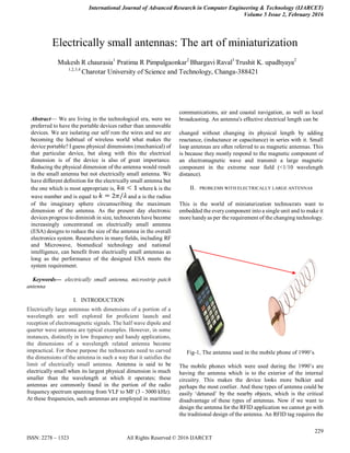
Fig-1, The antenna used in the mobile phone of 1990‘s.
The mobile phones which were used during the 1990‘s are
having the antenna which is to the exterior of the internal
circuitry. This makes the device looks more bulkier and
perhaps the most costlier. And these types of antenna could be
easily ‗detuned‘ by the nearby objects, which is the critical
disadvantage of these types of antennas. Now if we want to
design the antenna for the RFID application we cannot go with
the traditional design of the antenna. An RFID tag requires the
Electrically small antennas: The art of miniaturization
Mukesh R chaurasia1
Pratima R Pimpalgaonkar2
Bhargavi Raval3
Trushit K. upadhyaya2
1,2,3,4
Charotar University of Science and Technology, Changa-388421
2. International Journal of Advanced Research in Computer Engineering & Technology (IJARCET)
Volume 5 Issue 2, February 2016
230
ISSN: 2278 – 1323 All Rights Reserved © 2016 IJARCET
printed antenna whose size is very small as compared to the
operating wavelength of the antenna.
Again if we want to embedded the antenna in the device itself
the dimension of the antenna should be compatible with the
dimension of the device. Now a days the electronic devices are
shrinking to such an extent that the whole accessories along
with the antenna unit could be of 4.5 inch or even less than that.
Fig-2, The mobile phone of current technology.
PCS (Personal communication system) devices have become an
integral part of everyday life. The need to design the light
weight, small and handy mobile communication devices is
increasing rapidly, which emphasizes the RF engineers to
create the optimal antenna for the mobile application. Thus, the
size of the electronics required for mobile application has
decreased heavily during the past two decades, but the
performance has increased. But the size of the antenna is not
explored so far as compared to size of the electronic circuit. The
dimensions of the antenna are related to the wavelength of the
frequency of its operation and not with the latest technology.
The antenna could be reduced but with the sacrifice of
bandwidth, gain and efficiency. The technique of
miniaturization dealt with the adjustment i.e the dimensions
are shrinked but the characteristics changes compared to that of
the large antenna.
The current technologies which demand the electrically small
antenna are the MIMO system in wireless communication
where more than one antenna is needed for the reception of
signal. To integrate more than one antenna in such a small
circuit is a tedious task, ESA being the good candidate for the
MIMO system. The other application which demand an
electrically small antenna is RFID, an RFID tag consist of
mainly memory chip and a trans receiver the size of the tag is
typically very small it is one of the growing field of digital
communication the antenna used in such tag could be such that
the dimensions are of less than the operating wavelength of the
antenna.
III. ELECTRICALLY SMALL ANTENNA (ESA)
An ESA is an antenna that satisfies the condition ka < 1 ‗k‘ is
the wave number 2π/λ ‗a‘ is the radius of the minimum size
sphere that encloses the antenna .
Fig-3, An Electrically small antenna, the largest dimension of
the antenna are enclosed within the sphere of radius a.
The antenna here inside the imaginary sphere would be the one
with such characteristics of the electrically small antenna the
dimensions of which are directly related to the operating
wavelength of the antenna. 62 years past wheeler published his
paper which theoretically proves the fundamental limit on
achievable parameter called electrically small antennas
(ESAs). As the electronic devices continuously reducing in size
the demand for the electrically small antenna is growing. But
the miniaturization of electrically small antennas is still a
challenging issue for the RF engineers because of the
fundamental limits that needed to overcome for the
performance improvement of ESAs. According to Wheeler‘s
paper an ESA is one whose maximum dimension is less than
λ/(2π). This relation is often expressed as: ka < 1. k = 2π/λ, λ is
the free space wavelength, a is radius of sphere enclosing the
maximum dimension of the antenna. One year later to the
publication of Wheeler‘s work, Chu derived a theoretical
relationship between the dimensions of an antenna and its
minimum quality factor. This relation can be expressed as
Qchu = 1/ (ka) + 1/(ka)3. With decreasing electrically size,
ESAs exhibit decreasing radiation resistance, increasing
reactance, decreasing efficiency, and an increasing Q, which is
Thickness ~ 1cm
Length ~ 12cm
3. International Journal of Advanced Research in Computer Engineering & Technology (IJARCET)
Volume 5 Issue 2, February 2016
231
ISSN: 2278 – 1323 All Rights Reserved © 2016 IJARCET
equivalent to a decreasing bandwidth. ESAs are high
impedance mismatch relative to the characteristic impedance
of common transmission lines.
IV. DESIGN OF ESA FOR GPS APPLICATION
The technocrats in the past two decades have diverted their
attention towards the microstrip patch antennas only because
of the numerous advantage related to this particular type of
antenna it had got the planar geometry which make it to be
easily integrable with the existing circuit of application.
Presentlythis field has been considered as one of the influential
field of the antenna engineering. A unique and elementary
single band antenna is presented which is fed by a 50 ohm
coaxial line having a low-profile antenna structure with
meandering the portion of the patch In this research, a
meandered line electrically small microstrip patch antenna is
designed having the return loss bandwidths which suits for
GPS application (GPS L5 1.176 GHz) and having the
frequency band range from 1167 MHz to 1187 MHz and the
resonating frequency is at 1176 MHz, the simulation results for
return loss, impedance bandwidth, radiation patterns, and gain
are also discussed herein. Meandering line are adopted to
disturb the flow path of the surface current, by ultimately
offering the local inductive effect.
An electrically small antenna is being designed to operate
within the limits of the acceptable frequency. The synthesis of
more than one antenna for MIMO (multiple input multiple
output) application in each mobile terminal is a challenging
task. Electrically small antennas are the right applicants for
these applications. Meander line antennas are typical
electricallysmall antennas which are being preferred in MIMO
systems. The electrically small antenna is developed by
meandering the line from the patch.
Designing of the Antenna
i) Designing of the width of the
[1]
Here, fo is the center frequency, εr is relative permittivity and
c is the speed of light.
[2]
[3]
[4]
[5]
Equation [2] – [5] are used for designing the length of the
patch. Also t is the thickness of the substrate which is taken as
1.5mm
Here in the design we have meandered the patch just to make it
compact and to reduce the dimension just to integrate the
antenna with the thickness of the mobile devices bearing
thickness less than 1cm. Top view of the design is shown in
figure 4.
TABLE I
DIMENSION LIST
Title Measurement
Length of the rectangular patch (L) 25mm
Width of the rectangular patch (W) 25mm
Substrate thickness 1.5 mm
Dielectric Constant of Substrate 4.4
TABLE II
MATERIAL LIST
Title Material
Patch PEC
Substrate FR-4 Epoxy
Ground PEC
4. International Journal of Advanced Research in Computer Engineering & Technology (IJARCET)
Volume 5 Issue 2, February 2016
232
ISSN: 2278 – 1323 All Rights Reserved © 2016 IJARCET
Fig-4, Top view of the proposed design of electrically small
antenna.
From the patch nine (9) slots of 24 x 1 mm 2
is being meandered
to enhance the path for the surface current flow and to have the
better fringing fields out of the radiating patch and hence to
improve the radiation characteristics of the electrically small
microstrip patch antenna.
Simulation results and Discussions
The simulation of entire stuff is completed on HFSS 14, it is
one of the best accepted simulator of the RF antenna worldwide
and in industries too. Figure 2 shows the Return loss (S11) of
the design the return loss we are getting is around -12dB for the
center band frequency of 1.176 GHz for GPS application.
0.50 0.75 1.00 1.25 1.50 1.75 2.00
Freq[GHz]
-17.50
-15.00
-12.50
-10.00
-7.50
-5.00
-2.50
0.00
dB(S(1,1))
HFSSDesign1XYPlot1 ANSOFT
CurveInfo
dB(S(1,1))
Setup1:Sweep
fo=1.176GHz
Fig-5,Return loss (S11) of the Meandered ESA.
0.50 0.75 1.00 1.25 1.50 1.75 2.00
Freq[GHz]
0.00
20.00
40.00
60.00
80.00
100.00
120.00
140.00
VSWR(1)
HFSSDesign1XYPlot2 ANSOFT
CurveInfo
VSWR(1)
Setup1:Sweep
VSWR=1.38
Fig-6, Plot of VSWR of the meandered ESA
Fig-7 plot of Electric field intensity (V/m) of electrically small
antenna
Fig-8 Plot of Magnetic field intensity (A/m) of electrically
small antenna
24 mm
1 mm
5. International Journal of Advanced Research in Computer Engineering & Technology (IJARCET)
Volume 5 Issue 2, February 2016
233
ISSN: 2278 – 1323 All Rights Reserved © 2016 IJARCET
-39.60
-37.20
-34.80
-32.40
90
60
30
0
-30
-60
-90
-120
-150
-180
150
120
HFSSDesign1RadiationPattern1 ANSOFT
Curve Info
dB(GainTotal)
Setup1 : LastAdaptive
Freq='1.176GHz' Phi='0deg'
Fig-9, Radiation Pattern Of the Meandered Line Patch
Antenna.
V. CONCLUSION
Micro strip patch antenna is one of the dynamic fields in the
RF; these antennas have the great potential to cope up with any
application because of their numerous advantages. A
meandered line electrically small micro strip patch antenna is
designed and simulations results show that this antenna would
give optimum performance with the GPS application of center
frequency of 1.176 GHz. The Return loss of the antenna is
below -10dB from 1.167 GHz to 1.187 GHz. The antenna is
electricallysmall having ka = 0.51, which is good candidate for
the integration with the present day technology.
ACKNOWLEDGMENT
The authors would like to thank Dr. Trushit Upadhyaya for
his constant support and encouragement for the study
undertaken, the authors would also like to thank C S Patel
institute of technology a constituent of Charotar University of
science and Technology for providing such a wonderful
platform to carry out the study work.
REFERENCES
1. Wheeler, Harold. "Fundamental limitations of small
antennas." Proceedings of the IRE 35.12 (1947):
1479-1484.
2. Chu, Lan Jen. "Physical Limitations of
Omni‐Directional Antennas." Journal of applied
physics 19.12 (1948): 1163-1175.
3. Collin, R. E. "Minimum Q of small Antennas." Journal
of electromagnetic waves and applications 12.10
(1998): 1369-1393.
4. McLean, James S. "A re-examination of the
fundamental limits on the radiation Q of electrically
small antennas." Antennas and Propagation, IEEE
Transactions on 44.5 (1996): 672.
5. Harrington, Roger F. "Effect of antenna size on gain,
bandwidth, and efficiency."J. Res. Nat. Bur.
Stand 64.1 (1960): 1-12.
6. Azadegan, Reza, and Kamal Sarabandi. "A novel
approach for miniaturization of slot
antennas."Antennas and Propagation, IEEE
Transactions on 51.3 (2003): 421-429.
7. Alù, Andrea, and Nader Engheta. "Pairing an
epsilon-negative slab with a mu-negative slab:
resonance, tunneling and transparency." Antennas
and Propagation, IEEE Transactions on 51.10 (2003):
2558-2571.
8. Patel, R. H., Desai, A., Upadhyaya, T., & Patel, S. K.
―Design of S-Shape GPS Application Electrically
Small Antenna‖ Microwave and optical technology
Letters. 2015.
9. Deshmukh, Aaradhana, and K. P. Ray. "Analysis of
broadband Psi (ψ)-shaped microstrip
antennas." Antennas and Propagation Magazine,
IEEE 55.2 (2013): 107-123.
10. Izadi, Omid Hoseini, and Mandana Mehrparvar. "A
compact microstrip slot antenna with novel E-shaped
coupling aperture." Telecommunications (IST), 2010
5th International Symposium on. IEEE, 2010.
11. Jung, Chae-Hyun, Sang-Ho Lim, and Noh-Hoon
Myung. "Analysis of an H-shape cross slotted
aperture-coupled microstrip patch
antenna." Microwave Conference, 2009. APMC
2009. Asia Pacific. IEEE, 2009.
6. International Journal of Advanced Research in Computer Engineering & Technology (IJARCET)
Volume 5 Issue 2, February 2016
234
ISSN: 2278 – 1323 All Rights Reserved © 2016 IJARCET
12. Gao, S-C., et al. "Analysis of an H-shaped patch
antenna by using the FDTD method." Progress in
Electromagnetics Research 34 (2001): 165-187.
13. Ali, M. T., Nordin, N., Pasya, I., & Tan, M. M.
―H-shaped microstrip patch antenna using L-probe
fed for wideband applications‖. In Antennas and
Propagation (EUCAP), 2012 6th European
Conference on . IEEE. (pp. 2827-2831)
14. Bai, M., Xing, J., Wang, Z., & Yan, B. ― Design of an
H-shape cross slotted aperture-coupled microstrip
patch antenna‖. In Electromagnetics; Applications
and Student Innovation (iWEM), 2012 IEEE
International Workshop on IEEE (pp. 1-3).
15. Afzal, W., Rafique, U., Ahmed, M. M., Khan, M. A.,
& Mughal, F. A. (2012, May). ―A tri-band H-shaped
microstrip patch antenna for DCS and WLAN
applications‖. In Microwave Radar and Wireless
Communications (MIKON), 2012 19th International
Conference on IEEE (pp. 256-258).
16. Anguera, J., Boada, L., Puente, C., Borja, C., & Soler,
J. ―Stacked H-shaped microstrip patch
antenna‖. Antennas and Propagation, IEEE
Transactions on, 52(4), 983-993.
17. Mak, C. L., Luk, K. M., Lee, K. F., & Chow, Y. L.
―Experimental study of a microstrip patch antenna
with an L-shaped probe‖. Antennas and Propagation,
IEEE Transactions on, 48(5), 777-783.
18. Wu, T., Su, H., Gan, L., Chen, H., Huang, J., &
Zhang, H. ― A compact and broadband microstrip
stacked patch antenna with circular polarization for
2.45-GHz mobile RFID reader‖. Antennas and
Wireless Propagation Letters, IEEE, 12, 623-626.
19. Pandey, VijayK., and B. R. Visvakarma. "Theoretical
analysis of linear array antenna of stacked
patches." Indian Journal of Radio and Space
physics 34.2 (2005): 125.
20. Meshram, Manoj Kumar, and Babau R. Vishvakarma.
"Gap-coupled microstrip array antenna for
wide-band operation." International journal of
electronics88.11 (2001): 1161-1175.
21. Wang, Encheng, Jun Zheng, and Yanchun Liu. "A
novel dual-band patch antenna for WLAN
communication." Progress In Electromagnetics
Research C6 (2009): 93-102.
22. Sullivan, Patrick, and Daniel H. Schaubert. "Analysis
of an aperture coupled microstrip antenna." antennas
and propagation, ieee transactions on 34.8 (1986):
977-984.
23. Kirschning, Manfred, and Rolf H. Jansen. "Accurate
model for effective dielectric constant of microstrip
with validity up to millimetre-wave frequencies."
Electronics letters 18.6 (1982): 272-273.
24. Patel, Riki H., Arpan Desai, and Trushit Upadhyaya.
"A discussion on electrically small antenna
property." Microwave and Optical Technology
Letters57.10 (2015): 2386-2388.
25. Upadhyaya, Trushit K., Shiv Prasad Kosta, Rajeev
Jyoti, and Merih Palandöken. "Novel stacked
μ-negative material-loaded antenna for satellite
applications." International Journal of Microwave
and Wireless Technologies (2014): 1-7.
26. Upadhyaya, Trushit K., Shiv Prasad Kosta, Rajeev
Jyoti, and Merih Palandoken. "Negative refractive
index material-inspired 90-deg electrically tilted
ultra wideband resonator." Optical Engineering 53,
no. 10 (2014): 107104-107104.
27. Upadhyaya, T. K., Dwivedi, V. V., Kosta, S. P., &
Kosta, Y. P. ―Miniaturization of Tri Band Patch
Antenna Using Metamaterials‖. In Computational
Intelligence and Communication Networks (CICN),
2012 Fourth International Conference on IEEE (pp.
45-48).