Cancheck

The CAN Bus (Controller Area Network) is a serial two-wire full-duplex communication specification which conforms to the international standard ISO-11898 standard communication interface. The protocol of the CAN bus allows multiple nodes in a system to communicate efficiently with each other. It is already widely used in vehicle and vessel internal components; in recent years, it has seen adoption in data communications and control in industrial industry. The CAN Bus is used on the data transfer and control between controllers, a common setup in various industries. Examples include military use, electric power measurement, building automation, semiconductor equipment and elevator networks. This type of monitoring system is made up of many single-device combinations. To verify that things are working properly, one relies upon the integrity of software.

Empfohlen
Empfohlen
Weitere ähnliche Inhalte
Was ist angesagt?
Was ist angesagt? (20)
Andere mochten auch
Andere mochten auch (20)
Ähnlich wie Cancheck
Ähnlich wie Cancheck (20)
Mehr von ICP DAS USA, Inc.
Mehr von ICP DAS USA, Inc. (20)
Kürzlich hochgeladen
Kürzlich hochgeladen (20)
Cancheck
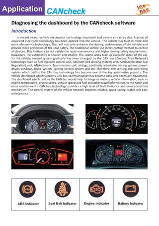
- 1. Application Diagnosing the dashboard by the CANcheck software In recent years, vehicle electronics technology improved and advances day by day. A great of advanced electronic technology has been applied into the vehicle. The vehicle has built-in more and more electronics technology. That will not only enhance the driving performance of the vehicle and provide more protection of the road safety. The traditional vehicle use direct-control method to control all devices. This method can not satisfy the rapid maintenance and higher driving safety requirements. Nowadays, the automotive is smaller and smaller. The coarse wires take up available space of the car. So the vehicle control system gradually has been changed by the CAN bus (Control Area Network) technology, such as fuel injection control unit, ABS(Anti-lock Braking System) unit, ASR(Acceleration Slip Regulation) unit, AT(Automatic Transmission) unit, airbags, continuity adjustable tracing system, power- driven windows, brake system, lighting control system and etc. Therefore, the sensing and controlling system which built-in the CAN bus technology has become one of the key automotive projects. The vehicle dashboard which supports CAN bus communication has become basic and necessary equipment. The dashboard which built-in the CAN bus would help to integrate various vehicle information, such as engine temperature, engine speed, vehicle speed and fuel and other travel information. In the harsh and noise environments, CAN bus technology provides a high level of fault tolerance and error correction mechanism. The control system of the vehicle network becomes reliable, space-saving, stable and easy maintenance. Introduction ABS Indicator Seat Belt Indicator Engine Indicator Battery Indicator
- 2. Application Oil Indicator Temp. Indicator Airbag Indicator Brake Indicator CAN bus Introduction CAN (Controller Area Network) is one of the most widely-applied fieldbus devices in the world. CAN was formulated its standards in early 1990s. At the beginning, CAN bus was designed for the automotive MCU communication to change the information among the ECU of the vehicles, forming automotive electronic control network. CAN bus was standardized (ISO 11898-1) in 1993.It is widely applied in various vehicles and electric devices. CAN is a serial bus control protocol, which is highly flexible and integrated. Besides, it provides high-level security and more efficient real-time control. The CAN hardware has the qualities of automatic error detection and priority determination on itself. The security of internet packets is checked by the hardware which completes multiple error checking in a very short time. Thus, the transmission of a large internet messages can be more reliable and more efficient. CAN bus features ■■ Low-cost fieldbus. ■■ High utilization for bus ■■ The fault node will off-line automatically and other nodes still work fine. ■■ High-speed data transmission (Up to 1Mbps). ■■ Support hardware the CAN message filter. ■■ Hardware provides reliable error handling and debugging mechanisms. ■■ After sending messages with disturbance, hardware can re-send automatically. ■■ With the arbitration mechanism, the messages will be scheduled and prevent from collisions. ◄◄ CAN bus Signal ▲▲ Arbitration Illustration
- 3. Application CANcheck Software Introduction CAN (Controller Area Network) is one of the most widely-applied fieldbus devices in the world. CAN was formulated its standards in early 1990s. At the beginning, CAN bus was designed for the automotive MCU communication to change the information among the ECU of the vehicles, forming automotive electronic control network. CAN bus was standardized (ISO 11898-1) in 1993.It is widely applied in various vehicles and electric devices. CAN is a serial bus control protocol, which is highly flexible and integrated. Besides, it provides high-level security and more efficient real-time control. The CAN hardware has the qualities of automatic error detection and priority determination on itself. The security of internet packets is checked by the hardware which completes multiple error checking in a very short time. Thus, the transmission of a large internet messages can be more reliable and more efficient. Different CAN instruments have different command sets; correspondingly, the return messages also differ. CANcheck can be used to perform verification of expected return messages – an easy way of error-checking operations. This feature does away with manual log-checking, and with it human error and tedium. CAN Message Modeling Users can model the vehicle CAN protocol or other special CAN protocol, set to the CANcheck software, the software will be able to follow the CAN command set and command transfer cycle. Users could provide the meaningful description for each CAN command. This helps to manage and identify all the complex CAN commands. CAN Message Management Different CAN message sets can be stored in different configuration files. The user can easily pipe different configuration files for different test cases. For example, a car factory can store several different cars' data in different configuration files, and then call the corresponding one as needed to test each car.
- 4. Application The CANcheck software provides the functionality of implementing the conversion of the CAN data. The CAN data of the specific CAN ID could be converted to the value of "long" type, "float" type and etc. When receiving the specific CAN messages, the CAN data will be converted to the specific data type and data value quickly and automatically. The users could focus on those converted value In some complex CAN control systems, such as temperature and humidity control, motion control with servo motor and other complex systems. The individual CAN messages include raw data which is not enough to get the physical information. The physical information always need combine some raw data with some mathematical operations, such as average temperature, entire flow, the coordinate translation and etc. It is a very The CAN messages which is transmitting within the CAN bus always contains much important information. The host computer also obtains that information which comes from the remote devices by the CAN bus. In general, the host computer acts as an important controller and it is difficult to obtain additional information from the host computer. The trend chart functionality of the CANcheck software allows the users to monitor some specific information in the CAN bus and transfers the raw CAN data into meaningful and important information directly, such as engine speed, vehicle speed, fuel and other information. Without any modification of the host computer, the users will be able to learn the details of the system only by monitoring the specific CAN messages in the CAN bus. Provide the real-time math function CAN Data Conversion CAN Monitor CAN Raw Data with Trend and need not to convert for each raw data manually. This conversion will help the users to deal with the huge raw data more friendly.
- 5. Application Supported OS: Windows XP, 7 Supported CAN boards, converters: PISO-CAN100U, PISO-CAN200U, PISO- CAN400U, PISO-CAN800U, PEX-CAN200i, PCM- CAN200, PCM-CAN200P, I-7530, I-7530-FT, I-7530A, I-7530A-MR, I-7540D, I-7540D-MTCP, I-7565, I-7565-H1, I-7565-H2 This software is free to download from the ICP DAS website, and allows fully functional usage for an unlimited number of ten-minute CANcheck software, the software will be able to follow the CAN command set and command transfer cycle. Users could provide the meaningful description for each CAN command. This helps to manage and identify all the complex CAN commands. CANcheck Feature: 1. No need to write any programs. The graphical interface is ready-made and easy to operate. 2. Limited to neither the vehicle nor instrument brand; it's interoperable. 3. The pre-loaded CAN communication protocol settings file protects against security leaks, ensuring safe operation. 4. Can set the returned CAN discrimination, eliminating the hassle of wading through logs and manually interpreting results. 5. Can be used to operate and diagnose lights, windows, dashboard or other vehicular electronic systems and components. 6. Supports CAN 2.0A and CAN 2.0B specifications. 7. The test command planning interface to set the test command, the transfer cycle, detecting the reply command and users' description. 8. Can store commands to the specific file. 9. Supports both the single- and multi- function tests. 10. Provides time stamps for the beginning and end of each test. 11. Displays real-time CAN status. 12. Supports a variety of ICP DAS CAN devices and operating systems, as shown below. Diagnosing the dashboard 1. Connect the CAN bus We use the high performance USB/CAN converter which is I-7565-H1. Connecting the I-7565-H1 with dashboard and running the CANcheck software. The topology is shown below. 2. Testing the indicator LED According to the CAN protocol of different vehicles, the CANcheck could send the CAN messages to the dashboard. We could check every fault indicator LED in the dashboard to verify if it works or not. difficult and time-consuming work by the human to calculate the large amounts of data in short time. The CANcheck software provides the math functionality which allows the users to write their own mathematical formula that contains four arithmetic operations, but also includes trigonometry, square root operations and etc.the users can edit the appropriate mathematical formula to obtain the important result. As a result, the users can monitor the actual physical data easily and directly. sessions without requiring the purchase of a USB dongle. Refer to the following website for more information. http://www.icpdas.com/products/Remote_ IO/can_bus/CANcheck.htm
- 6. Application 4. Testing OBD-II Command OBD-II (On-board diagnostics/SAE J1797) is CAN protocol used to request data from a vehicle which is used as a diagnostic tool. We could read the raw data of the vehicle, such as the Catalyst Temperature, O2 Sensor Monitor, Misfire, Fuel Trim and etc. 5. Testing with real vehicle from OBD-II port We use the USB/CAN converter which is the I-7565-H1. The picture below shown how the I-7565-H1 connect to the OBD-II port of the Toyota Yaris. 6.Checking the sensors of the vehicle when turn on power After turn on the power, the dashboard will check important sensors automatically. After checking the sensors and they work fine, the fault indicator LED will turn off. The picture below shows the fault LEDs. 3.Testing the Vehicle Information The CANcheck could send different vehicle CAN protocols. We have tried to simulate various engine data and vehicle information. The dashboard would show the corresponding data which the CANcheck has sent. 7.Checking the dashboard and OBD-II when turn on the engine After turn on the engine, all raw data will be sent to dashboard and OBD-II port. We developed simple utility to read the CAN messages which are the engine speed and vehicle speed. We found the dashboard and our utility showed the same information below.
- 7. Application Conclusion The CANcheck is not only able to verify the vehicle dashboard, but also could check the vehicle sensors of safety system, such as air bag, ABS, breaking system and etc. The CANcheck is software which is used to verify the functions of CAN devices from any manufacturers. It provides users to design the test commands and the expected response, and arrange the test procedure for their CAN 8. Checking the dashboard and OBD-II when driving We want to check the changes of the raw data. We drive out and show the received information of the CAN messages. Even the vehicle was moving, we found the dashboard and our utility still showed the same information below. products.When starting the test, the software will go When starting the test, the software will go the predefined procedure to send the specific messages and check if the corresponding responses are correct. This is not only useful for the QC of the CAN devices such as light, dashboard …, but also helpful to diagnostic the CAN application systems. Here shows the features. (1) No programming knowledge is needed. The graphical HMI provides easy-to-use operation interface for rule configurations and testing procedures. (2) Suits to test all kinds of CAN devices which follows the ISO 11898-2 specification. (3) The protocol configuration file protects private CAN communication protocol from disclosing the business or technique secret. (4) Supports the verification of the replied CAN messages from the tested units. (5)Supports CAN 2.0A and CAN 2.0B specifications. (6) Allows configuring the test commands, the test cycle, the test duration, the expected responses, and the description of the test procedure. (7) Saves the test procedures to the specific file. (8) Supports both the single-task and multi- tasks tests. (9) Provides time stamps to recode the start and end time of each test item. (10) Displays the CAN bus status immediately.