SlideShare ist ein Scribd-Unternehmen logo
1 von 4
Transistor as a Switch
If the electronic circuit uses the Transistor as a Switch, then the biasing of the transistor, either it
is an NPN or a PNP is arranged to operate at the sides of the V-I characteristics curves as shown
below. The areas of operation for the transistor as a switch are known as the Saturation
Region and the Cut-off Region. This means then that we can use the operating Q-point biasing
and the voltage divider circuitry required for the amplification, as a transistor switch by moving
it back and forth between the fully-OFF that is the cut-off region and the fully-ON the saturation
region.
Transistor operates as an "open switch".
In the cutoff region the operating conditions of the transistor are zero input base current ( IB ),
the zero output collector current ( IC ) and maximum collector voltage ( VCE ). So there is a large
depletion layer and no current flows through the device.
· The input and Base are grounded (0v)
· Base-Emitter voltage VBE < 0.7V
· Base-Emitter junction is reverse biased
· Base-Collector junction is reverse biased
· Transistor is fully-OFF
· No Collector current flows ( IC = 0 )
· VOUT = VCE = VCC = "1".
Transistor operates as a "closed switch"
· In the saturation region the transistor will be biased so that the maximum amount
of base current is applied, resulting in maximum collector current resulting in the
minimum collector emitter voltage drop. So the depletion layer being as small as possible and
maximum current flowing through the transistor. Therefore the transistor is switched "Fully-
ON".
· The input and Base are connected to VCC
· Base-Emitter voltage VBE > 0.7V
· Base-Emitter junction is forward biased
· Base-Collector junction is forward biased
· Transistor is "fully-ON" (saturation region)
· Max Collector current flows (IC = Vcc/RL)
· VCE = 0 (ideal saturation)
· VOUT = VCE = "0"
Applications:
Transistor switches are widely used for controlling the high power devices such as
motors, solenoids or lamps. Transistor switches can also used in digital electronics and logic
gate circuits for there control.
Astable Multivibrator:
 This is also called free running relaxation oscillator.
 Used to generate square waveform.
 Two identical NPN transistors Q1 and Q2 are used
 RC1 = RC2 = RC ; R1 = R2 = R ; C1 = C2 = C ;
 Transistor Q1 is biased through VCC via resistor RC1.
 Transistor Q2 is biased through VCC via resistor RC2.
 The output of Q1 is coupled to the input of transistor Q2 through capacitor C1.
 The output of Q2 is coupled to the input of transistor Q1 through capacitor C2.
 1800 phase shift is provided by the amplifier and the other 1800 phase shift is provided
by the capacitor. Hence the feedback signal has a total of 3600 phase shift. Thus the
feedback is positive and works as an oscillator.
Circuit operation:
 When D.C. supply is switched ON, one of the transistor will start conducting more than
the other due to some imbalance in the circuit. If Q1 starts conducting, it is in Saturation
and transistor Q2 is in Cut-off.
 When Q1 is ON and Q2 is OFF, the capacitor is charging towards the voltage VCC through
R1. The charging takes place exponentially with time constant R1.C1.
 Since the base of Q1 is connected to capacitor C1, voltage at VB2 increases.
 This leads to transistor Q2 to operate at saturation and its collector voltage VC1 falls and
hence cuts-off the transistor Q1.
 Thus, the output of the transistor continuously switches between On and OFF states,
generating a square wave.
Applications:
Multivibrators Used in electronic circuits such as computers, control systems and
communication systems.
 Astable Multivibrators are used as
1. Square wave generators
2. Voltage to frequency converters
3. Pulse Synchronisation
Bistable Multivibrator
 This is also called flip-flop.
 It has two stable states.
 The two states are maintained as long as no external trigger is applied.
 When an external trigger or a short pulse is applied to any one of the inputs, the Set or
Reset state is attained by the circuit.
 Two identical NPN transistors Q1 and Q2 are used
 RC1 = RC2 = RC ; R1 = R2 = R ; C1 = C2 = C ;
 Transistor Q1 is biased through VCC via resistor RC1.
 Transistor Q2 is biased through VCC via resistor RC2.
 The output of Q1 is coupled to the input of transistor Q2 through Resistor R1
 The output of Q2 is coupled to the input of transistor Q1 through Resistor R2
 The capacitors C1 and C2 are speed up capacitors, which increases the speed of the
circuit in making abrupt transition from one stable state to another.
 The base resistors R3 and R4 are connected to common source –VBB.
 The output is available at the two collector terminals of the transistors, which are
complements of each other.
Circuit operation:
 When D.C. supply is switched ON, one of the transistor will start conducting more than
the other due to some imbalance in the circuit.
 If Q1 starts conducting, it is in Saturation (ON) and transistor Q2 is in Cut-off(OFF).
 This is a stable state of the circuit, which will remain in this state till a trigger pulse is
applied.
 A pulse applied at Reset input causes the transistor Q2 to conduct. As the collector
voltage of this transistor falls, Q1 goes to cut-off. Thus, Q2 ON and Q1 is OFF.
 A pulse applied at Set input causes the transistor Q1 to conduct. As the collector voltage
of this transistor falls, Q2 goes to cut-off. Thus, Q1 ON and Q2 is OFF.
 Thus, the collector output of the transistor changes its state when Set and Reset inputs
are given, and these states are stable as long as no trigger is applied, thus storing the
state.
Applications:
 Used as Flip-flops in digital circuits.
 Used as memory elements in Shift registers, counters etc.
 Generation and processing of pulse type waveforms

Weitere ähnliche Inhalte

Was ist angesagt?

l control single phase rectifier
l control single phase rectifierl control single phase rectifier
l control single phase rectifierZahid Nawaz
 
Power electronics Phase Controlled Rectifiers - SCR
Power electronics   Phase Controlled Rectifiers - SCRPower electronics   Phase Controlled Rectifiers - SCR
Power electronics Phase Controlled Rectifiers - SCRBurdwan University
 
Working of three phase rectifier with sourse impedance
Working of three phase rectifier with sourse impedanceWorking of three phase rectifier with sourse impedance
Working of three phase rectifier with sourse impedanceManju Karthick
 
Snubber circuits
Snubber circuitsSnubber circuits
Snubber circuitshugosaldano
 
Silicon Control Rectifier Phase Control
Silicon Control Rectifier Phase ControlSilicon Control Rectifier Phase Control
Silicon Control Rectifier Phase ControlDerrick Tiew
 
Thyristors (2)
Thyristors (2)Thyristors (2)
Thyristors (2)Chethan Sp
 
Thyristor commutation techniques
Thyristor commutation techniquesThyristor commutation techniques
Thyristor commutation techniquesVinod Srivastava
 
Voltage Doubler using NE 555 timer IC
Voltage Doubler using NE 555 timer IC Voltage Doubler using NE 555 timer IC
Voltage Doubler using NE 555 timer IC Partha P. Mishra
 
Controlled Rectifier
Controlled RectifierControlled Rectifier
Controlled RectifierFaraz Ahmed
 
1 ph semi converter (r-l load)
1 ph semi converter (r-l load)1 ph semi converter (r-l load)
1 ph semi converter (r-l load)avi1001
 
Thyristors,Commutayion of Thyristor, Power Electronics
Thyristors,Commutayion of Thyristor, Power ElectronicsThyristors,Commutayion of Thyristor, Power Electronics
Thyristors,Commutayion of Thyristor, Power ElectronicsDurgesh Singh
 

Was ist angesagt? (19)

1 phase semiconverter
1 phase semiconverter1 phase semiconverter
1 phase semiconverter
 
l control single phase rectifier
l control single phase rectifierl control single phase rectifier
l control single phase rectifier
 
L5 thyristor protection
L5 thyristor protectionL5 thyristor protection
L5 thyristor protection
 
L12 ujt based triggering circuit
L12 ujt based triggering circuitL12 ujt based triggering circuit
L12 ujt based triggering circuit
 
tca785
tca785tca785
tca785
 
Single Phase Converter
Single Phase ConverterSingle Phase Converter
Single Phase Converter
 
Power electronics Phase Controlled Rectifiers - SCR
Power electronics   Phase Controlled Rectifiers - SCRPower electronics   Phase Controlled Rectifiers - SCR
Power electronics Phase Controlled Rectifiers - SCR
 
Working of three phase rectifier with sourse impedance
Working of three phase rectifier with sourse impedanceWorking of three phase rectifier with sourse impedance
Working of three phase rectifier with sourse impedance
 
Snubber circuits
Snubber circuitsSnubber circuits
Snubber circuits
 
Scr
ScrScr
Scr
 
Silicon Control Rectifier Phase Control
Silicon Control Rectifier Phase ControlSilicon Control Rectifier Phase Control
Silicon Control Rectifier Phase Control
 
Thyristors (2)
Thyristors (2)Thyristors (2)
Thyristors (2)
 
Dual converter
Dual converterDual converter
Dual converter
 
Thyristor commutation techniques
Thyristor commutation techniquesThyristor commutation techniques
Thyristor commutation techniques
 
Thyristor
Thyristor Thyristor
Thyristor
 
Voltage Doubler using NE 555 timer IC
Voltage Doubler using NE 555 timer IC Voltage Doubler using NE 555 timer IC
Voltage Doubler using NE 555 timer IC
 
Controlled Rectifier
Controlled RectifierControlled Rectifier
Controlled Rectifier
 
1 ph semi converter (r-l load)
1 ph semi converter (r-l load)1 ph semi converter (r-l load)
1 ph semi converter (r-l load)
 
Thyristors,Commutayion of Thyristor, Power Electronics
Thyristors,Commutayion of Thyristor, Power ElectronicsThyristors,Commutayion of Thyristor, Power Electronics
Thyristors,Commutayion of Thyristor, Power Electronics
 

Ähnlich wie Transistor as a switch (2)

Multivibrators
MultivibratorsMultivibrators
MultivibratorsDenys Beny
 
Multivibrators-Astable, Bistable and Monostable.pptx
Multivibrators-Astable, Bistable and Monostable.pptxMultivibrators-Astable, Bistable and Monostable.pptx
Multivibrators-Astable, Bistable and Monostable.pptxpadmapriyaMarineEngg
 
Relaxation oscillators
Relaxation oscillatorsRelaxation oscillators
Relaxation oscillatorsTouqeer Jumani
 
Basic Electronics 5 by Dr. Mathivanan Velumani
Basic Electronics 5 by Dr. Mathivanan VelumaniBasic Electronics 5 by Dr. Mathivanan Velumani
Basic Electronics 5 by Dr. Mathivanan VelumaniMathivanan Velumani
 
EST 130, Transistor Biasing and Amplification.
EST 130, Transistor Biasing and Amplification.EST 130, Transistor Biasing and Amplification.
EST 130, Transistor Biasing and Amplification.CKSunith1
 
Colpitts oscillator
Colpitts oscillatorColpitts oscillator
Colpitts oscillatorMdHaque78
 
Short notes on digital electronics for specialist officer it exam by das sir,...
Short notes on digital electronics for specialist officer it exam by das sir,...Short notes on digital electronics for specialist officer it exam by das sir,...
Short notes on digital electronics for specialist officer it exam by das sir,...Tamal Kumar Das
 
8510651.pptx
8510651.pptx8510651.pptx
8510651.pptxIndroHat
 
direct coupled transistor logic
direct coupled transistor logicdirect coupled transistor logic
direct coupled transistor logicsonalijagtap15
 
Power Electronics - Phase Controlled Converters.pptx
Power Electronics - Phase Controlled Converters.pptxPower Electronics - Phase Controlled Converters.pptx
Power Electronics - Phase Controlled Converters.pptxPoornima D
 
Mini project submission
Mini project submissionMini project submission
Mini project submissionAkshay Ajay
 

Ähnlich wie Transistor as a switch (2) (20)

UNIT - 6.pdf
UNIT - 6.pdfUNIT - 6.pdf
UNIT - 6.pdf
 
Multivibrators
MultivibratorsMultivibrators
Multivibrators
 
Multivabtor.pptx
Multivabtor.pptxMultivabtor.pptx
Multivabtor.pptx
 
Multivibrators.pptx
Multivibrators.pptxMultivibrators.pptx
Multivibrators.pptx
 
Multivibrators-Astable, Bistable and Monostable.pptx
Multivibrators-Astable, Bistable and Monostable.pptxMultivibrators-Astable, Bistable and Monostable.pptx
Multivibrators-Astable, Bistable and Monostable.pptx
 
Transistor as a switch
Transistor as a switch Transistor as a switch
Transistor as a switch
 
Relaxation oscillators
Relaxation oscillatorsRelaxation oscillators
Relaxation oscillators
 
Basic Electronics 5 by Dr. Mathivanan Velumani
Basic Electronics 5 by Dr. Mathivanan VelumaniBasic Electronics 5 by Dr. Mathivanan Velumani
Basic Electronics 5 by Dr. Mathivanan Velumani
 
Multivibrator
MultivibratorMultivibrator
Multivibrator
 
UNIT-5.pptx.ppt
UNIT-5.pptx.pptUNIT-5.pptx.ppt
UNIT-5.pptx.ppt
 
Switching regulators
Switching regulatorsSwitching regulators
Switching regulators
 
EST 130, Transistor Biasing and Amplification.
EST 130, Transistor Biasing and Amplification.EST 130, Transistor Biasing and Amplification.
EST 130, Transistor Biasing and Amplification.
 
Colpitts oscillator
Colpitts oscillatorColpitts oscillator
Colpitts oscillator
 
Oscillator
OscillatorOscillator
Oscillator
 
Short notes on digital electronics for specialist officer it exam by das sir,...
Short notes on digital electronics for specialist officer it exam by das sir,...Short notes on digital electronics for specialist officer it exam by das sir,...
Short notes on digital electronics for specialist officer it exam by das sir,...
 
8510651.pptx
8510651.pptx8510651.pptx
8510651.pptx
 
direct coupled transistor logic
direct coupled transistor logicdirect coupled transistor logic
direct coupled transistor logic
 
Power Electronics - Phase Controlled Converters.pptx
Power Electronics - Phase Controlled Converters.pptxPower Electronics - Phase Controlled Converters.pptx
Power Electronics - Phase Controlled Converters.pptx
 
Inverter
InverterInverter
Inverter
 
Mini project submission
Mini project submissionMini project submission
Mini project submission
 

Mehr von HarshitParkar6677 (20)

Wi fi hacking
Wi fi hackingWi fi hacking
Wi fi hacking
 
D dos attack
D dos attackD dos attack
D dos attack
 
Notes chapter 6
Notes chapter  6Notes chapter  6
Notes chapter 6
 
Interface notes
Interface notesInterface notes
Interface notes
 
Chapter6 2
Chapter6 2Chapter6 2
Chapter6 2
 
Chapter6
Chapter6Chapter6
Chapter6
 
8086 cpu 1
8086 cpu 18086 cpu 1
8086 cpu 1
 
Chapter 6 notes
Chapter 6 notesChapter 6 notes
Chapter 6 notes
 
Chapter 5 notes
Chapter 5 notesChapter 5 notes
Chapter 5 notes
 
Chap6 procedures &amp; macros
Chap6 procedures &amp; macrosChap6 procedures &amp; macros
Chap6 procedures &amp; macros
 
Chapter 5 notes new
Chapter 5 notes newChapter 5 notes new
Chapter 5 notes new
 
Notes arithmetic instructions
Notes arithmetic instructionsNotes arithmetic instructions
Notes arithmetic instructions
 
Notes all instructions
Notes all instructionsNotes all instructions
Notes all instructions
 
Notes aaa aa
Notes aaa aaNotes aaa aa
Notes aaa aa
 
Notes 8086 instruction format
Notes 8086 instruction formatNotes 8086 instruction format
Notes 8086 instruction format
 
Misc
MiscMisc
Misc
 
Copy of 8086inst logical
Copy of 8086inst logicalCopy of 8086inst logical
Copy of 8086inst logical
 
Copy of 8086inst logical
Copy of 8086inst logicalCopy of 8086inst logical
Copy of 8086inst logical
 
Chapter3 program flow control instructions
Chapter3 program flow control instructionsChapter3 program flow control instructions
Chapter3 program flow control instructions
 
Chapter3 8086inst stringsl
Chapter3 8086inst stringslChapter3 8086inst stringsl
Chapter3 8086inst stringsl
 

Kürzlich hochgeladen

Gurgaon ✡️9711147426✨Call In girls Gurgaon Sector 51 escort service
Gurgaon ✡️9711147426✨Call In girls Gurgaon Sector 51 escort serviceGurgaon ✡️9711147426✨Call In girls Gurgaon Sector 51 escort service
Gurgaon ✡️9711147426✨Call In girls Gurgaon Sector 51 escort servicejennyeacort
 
Class 1 | NFPA 72 | Overview Fire Alarm System
Class 1 | NFPA 72 | Overview Fire Alarm SystemClass 1 | NFPA 72 | Overview Fire Alarm System
Class 1 | NFPA 72 | Overview Fire Alarm Systemirfanmechengr
 
Arduino_CSE ece ppt for working and principal of arduino.ppt
Arduino_CSE ece ppt for working and principal of arduino.pptArduino_CSE ece ppt for working and principal of arduino.ppt
Arduino_CSE ece ppt for working and principal of arduino.pptSAURABHKUMAR892774
 
Piping Basic stress analysis by engineering
Piping Basic stress analysis by engineeringPiping Basic stress analysis by engineering
Piping Basic stress analysis by engineeringJuanCarlosMorales19600
 
Why does (not) Kafka need fsync: Eliminating tail latency spikes caused by fsync
Why does (not) Kafka need fsync: Eliminating tail latency spikes caused by fsyncWhy does (not) Kafka need fsync: Eliminating tail latency spikes caused by fsync
Why does (not) Kafka need fsync: Eliminating tail latency spikes caused by fsyncssuser2ae721
 
Study on Air-Water & Water-Water Heat Exchange in a Finned Tube Exchanger
Study on Air-Water & Water-Water Heat Exchange in a Finned Tube ExchangerStudy on Air-Water & Water-Water Heat Exchange in a Finned Tube Exchanger
Study on Air-Water & Water-Water Heat Exchange in a Finned Tube ExchangerAnamika Sarkar
 
Risk Assessment For Installation of Drainage Pipes.pdf
Risk Assessment For Installation of Drainage Pipes.pdfRisk Assessment For Installation of Drainage Pipes.pdf
Risk Assessment For Installation of Drainage Pipes.pdfROCENODodongVILLACER
 
INFLUENCE OF NANOSILICA ON THE PROPERTIES OF CONCRETE
INFLUENCE OF NANOSILICA ON THE PROPERTIES OF CONCRETEINFLUENCE OF NANOSILICA ON THE PROPERTIES OF CONCRETE
INFLUENCE OF NANOSILICA ON THE PROPERTIES OF CONCRETEroselinkalist12
 
Introduction to Machine Learning Unit-3 for II MECH
Introduction to Machine Learning Unit-3 for II MECHIntroduction to Machine Learning Unit-3 for II MECH
Introduction to Machine Learning Unit-3 for II MECHC Sai Kiran
 
TechTAC® CFD Report Summary: A Comparison of Two Types of Tubing Anchor Catchers
TechTAC® CFD Report Summary: A Comparison of Two Types of Tubing Anchor CatchersTechTAC® CFD Report Summary: A Comparison of Two Types of Tubing Anchor Catchers
TechTAC® CFD Report Summary: A Comparison of Two Types of Tubing Anchor Catcherssdickerson1
 
Application of Residue Theorem to evaluate real integrations.pptx
Application of Residue Theorem to evaluate real integrations.pptxApplication of Residue Theorem to evaluate real integrations.pptx
Application of Residue Theorem to evaluate real integrations.pptx959SahilShah
 
Sachpazis Costas: Geotechnical Engineering: A student's Perspective Introduction
Sachpazis Costas: Geotechnical Engineering: A student's Perspective IntroductionSachpazis Costas: Geotechnical Engineering: A student's Perspective Introduction
Sachpazis Costas: Geotechnical Engineering: A student's Perspective IntroductionDr.Costas Sachpazis
 
lifi-technology with integration of IOT.pptx
lifi-technology with integration of IOT.pptxlifi-technology with integration of IOT.pptx
lifi-technology with integration of IOT.pptxsomshekarkn64
 
Software and Systems Engineering Standards: Verification and Validation of Sy...
Software and Systems Engineering Standards: Verification and Validation of Sy...Software and Systems Engineering Standards: Verification and Validation of Sy...
Software and Systems Engineering Standards: Verification and Validation of Sy...VICTOR MAESTRE RAMIREZ
 
Past, Present and Future of Generative AI
Past, Present and Future of Generative AIPast, Present and Future of Generative AI
Past, Present and Future of Generative AIabhishek36461
 
Unit7-DC_Motors nkkjnsdkfnfcdfknfdgfggfg
Unit7-DC_Motors nkkjnsdkfnfcdfknfdgfggfgUnit7-DC_Motors nkkjnsdkfnfcdfknfdgfggfg
Unit7-DC_Motors nkkjnsdkfnfcdfknfdgfggfgsaravananr517913
 

Kürzlich hochgeladen (20)

Gurgaon ✡️9711147426✨Call In girls Gurgaon Sector 51 escort service
Gurgaon ✡️9711147426✨Call In girls Gurgaon Sector 51 escort serviceGurgaon ✡️9711147426✨Call In girls Gurgaon Sector 51 escort service
Gurgaon ✡️9711147426✨Call In girls Gurgaon Sector 51 escort service
 
Class 1 | NFPA 72 | Overview Fire Alarm System
Class 1 | NFPA 72 | Overview Fire Alarm SystemClass 1 | NFPA 72 | Overview Fire Alarm System
Class 1 | NFPA 72 | Overview Fire Alarm System
 
Arduino_CSE ece ppt for working and principal of arduino.ppt
Arduino_CSE ece ppt for working and principal of arduino.pptArduino_CSE ece ppt for working and principal of arduino.ppt
Arduino_CSE ece ppt for working and principal of arduino.ppt
 
Piping Basic stress analysis by engineering
Piping Basic stress analysis by engineeringPiping Basic stress analysis by engineering
Piping Basic stress analysis by engineering
 
Why does (not) Kafka need fsync: Eliminating tail latency spikes caused by fsync
Why does (not) Kafka need fsync: Eliminating tail latency spikes caused by fsyncWhy does (not) Kafka need fsync: Eliminating tail latency spikes caused by fsync
Why does (not) Kafka need fsync: Eliminating tail latency spikes caused by fsync
 
9953056974 Call Girls In South Ex, Escorts (Delhi) NCR.pdf
9953056974 Call Girls In South Ex, Escorts (Delhi) NCR.pdf9953056974 Call Girls In South Ex, Escorts (Delhi) NCR.pdf
9953056974 Call Girls In South Ex, Escorts (Delhi) NCR.pdf
 
Study on Air-Water & Water-Water Heat Exchange in a Finned Tube Exchanger
Study on Air-Water & Water-Water Heat Exchange in a Finned Tube ExchangerStudy on Air-Water & Water-Water Heat Exchange in a Finned Tube Exchanger
Study on Air-Water & Water-Water Heat Exchange in a Finned Tube Exchanger
 
Risk Assessment For Installation of Drainage Pipes.pdf
Risk Assessment For Installation of Drainage Pipes.pdfRisk Assessment For Installation of Drainage Pipes.pdf
Risk Assessment For Installation of Drainage Pipes.pdf
 
INFLUENCE OF NANOSILICA ON THE PROPERTIES OF CONCRETE
INFLUENCE OF NANOSILICA ON THE PROPERTIES OF CONCRETEINFLUENCE OF NANOSILICA ON THE PROPERTIES OF CONCRETE
INFLUENCE OF NANOSILICA ON THE PROPERTIES OF CONCRETE
 
Introduction to Machine Learning Unit-3 for II MECH
Introduction to Machine Learning Unit-3 for II MECHIntroduction to Machine Learning Unit-3 for II MECH
Introduction to Machine Learning Unit-3 for II MECH
 
TechTAC® CFD Report Summary: A Comparison of Two Types of Tubing Anchor Catchers
TechTAC® CFD Report Summary: A Comparison of Two Types of Tubing Anchor CatchersTechTAC® CFD Report Summary: A Comparison of Two Types of Tubing Anchor Catchers
TechTAC® CFD Report Summary: A Comparison of Two Types of Tubing Anchor Catchers
 
Application of Residue Theorem to evaluate real integrations.pptx
Application of Residue Theorem to evaluate real integrations.pptxApplication of Residue Theorem to evaluate real integrations.pptx
Application of Residue Theorem to evaluate real integrations.pptx
 
Sachpazis Costas: Geotechnical Engineering: A student's Perspective Introduction
Sachpazis Costas: Geotechnical Engineering: A student's Perspective IntroductionSachpazis Costas: Geotechnical Engineering: A student's Perspective Introduction
Sachpazis Costas: Geotechnical Engineering: A student's Perspective Introduction
 
Design and analysis of solar grass cutter.pdf
Design and analysis of solar grass cutter.pdfDesign and analysis of solar grass cutter.pdf
Design and analysis of solar grass cutter.pdf
 
lifi-technology with integration of IOT.pptx
lifi-technology with integration of IOT.pptxlifi-technology with integration of IOT.pptx
lifi-technology with integration of IOT.pptx
 
young call girls in Green Park🔝 9953056974 🔝 escort Service
young call girls in Green Park🔝 9953056974 🔝 escort Serviceyoung call girls in Green Park🔝 9953056974 🔝 escort Service
young call girls in Green Park🔝 9953056974 🔝 escort Service
 
Software and Systems Engineering Standards: Verification and Validation of Sy...
Software and Systems Engineering Standards: Verification and Validation of Sy...Software and Systems Engineering Standards: Verification and Validation of Sy...
Software and Systems Engineering Standards: Verification and Validation of Sy...
 
Past, Present and Future of Generative AI
Past, Present and Future of Generative AIPast, Present and Future of Generative AI
Past, Present and Future of Generative AI
 
young call girls in Rajiv Chowk🔝 9953056974 🔝 Delhi escort Service
young call girls in Rajiv Chowk🔝 9953056974 🔝 Delhi escort Serviceyoung call girls in Rajiv Chowk🔝 9953056974 🔝 Delhi escort Service
young call girls in Rajiv Chowk🔝 9953056974 🔝 Delhi escort Service
 
Unit7-DC_Motors nkkjnsdkfnfcdfknfdgfggfg
Unit7-DC_Motors nkkjnsdkfnfcdfknfdgfggfgUnit7-DC_Motors nkkjnsdkfnfcdfknfdgfggfg
Unit7-DC_Motors nkkjnsdkfnfcdfknfdgfggfg
 

Transistor as a switch (2)

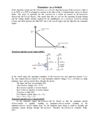
  • 1. Transistor as a Switch If the electronic circuit uses the Transistor as a Switch, then the biasing of the transistor, either it is an NPN or a PNP is arranged to operate at the sides of the V-I characteristics curves as shown below. The areas of operation for the transistor as a switch are known as the Saturation Region and the Cut-off Region. This means then that we can use the operating Q-point biasing and the voltage divider circuitry required for the amplification, as a transistor switch by moving it back and forth between the fully-OFF that is the cut-off region and the fully-ON the saturation region. Transistor operates as an "open switch". In the cutoff region the operating conditions of the transistor are zero input base current ( IB ), the zero output collector current ( IC ) and maximum collector voltage ( VCE ). So there is a large depletion layer and no current flows through the device. · The input and Base are grounded (0v) · Base-Emitter voltage VBE < 0.7V · Base-Emitter junction is reverse biased · Base-Collector junction is reverse biased · Transistor is fully-OFF · No Collector current flows ( IC = 0 ) · VOUT = VCE = VCC = "1". Transistor operates as a "closed switch" · In the saturation region the transistor will be biased so that the maximum amount of base current is applied, resulting in maximum collector current resulting in the minimum collector emitter voltage drop. So the depletion layer being as small as possible and maximum current flowing through the transistor. Therefore the transistor is switched "Fully- ON".
  • 2. · The input and Base are connected to VCC · Base-Emitter voltage VBE > 0.7V · Base-Emitter junction is forward biased · Base-Collector junction is forward biased · Transistor is "fully-ON" (saturation region) · Max Collector current flows (IC = Vcc/RL) · VCE = 0 (ideal saturation) · VOUT = VCE = "0" Applications: Transistor switches are widely used for controlling the high power devices such as motors, solenoids or lamps. Transistor switches can also used in digital electronics and logic gate circuits for there control. Astable Multivibrator:  This is also called free running relaxation oscillator.  Used to generate square waveform.  Two identical NPN transistors Q1 and Q2 are used  RC1 = RC2 = RC ; R1 = R2 = R ; C1 = C2 = C ;  Transistor Q1 is biased through VCC via resistor RC1.  Transistor Q2 is biased through VCC via resistor RC2.  The output of Q1 is coupled to the input of transistor Q2 through capacitor C1.  The output of Q2 is coupled to the input of transistor Q1 through capacitor C2.  1800 phase shift is provided by the amplifier and the other 1800 phase shift is provided by the capacitor. Hence the feedback signal has a total of 3600 phase shift. Thus the feedback is positive and works as an oscillator. Circuit operation:  When D.C. supply is switched ON, one of the transistor will start conducting more than the other due to some imbalance in the circuit. If Q1 starts conducting, it is in Saturation and transistor Q2 is in Cut-off.  When Q1 is ON and Q2 is OFF, the capacitor is charging towards the voltage VCC through R1. The charging takes place exponentially with time constant R1.C1.  Since the base of Q1 is connected to capacitor C1, voltage at VB2 increases.  This leads to transistor Q2 to operate at saturation and its collector voltage VC1 falls and hence cuts-off the transistor Q1.  Thus, the output of the transistor continuously switches between On and OFF states, generating a square wave.
  • 3. Applications: Multivibrators Used in electronic circuits such as computers, control systems and communication systems.  Astable Multivibrators are used as 1. Square wave generators 2. Voltage to frequency converters 3. Pulse Synchronisation Bistable Multivibrator  This is also called flip-flop.  It has two stable states.  The two states are maintained as long as no external trigger is applied.  When an external trigger or a short pulse is applied to any one of the inputs, the Set or Reset state is attained by the circuit.  Two identical NPN transistors Q1 and Q2 are used  RC1 = RC2 = RC ; R1 = R2 = R ; C1 = C2 = C ;  Transistor Q1 is biased through VCC via resistor RC1.  Transistor Q2 is biased through VCC via resistor RC2.
  • 4.  The output of Q1 is coupled to the input of transistor Q2 through Resistor R1  The output of Q2 is coupled to the input of transistor Q1 through Resistor R2  The capacitors C1 and C2 are speed up capacitors, which increases the speed of the circuit in making abrupt transition from one stable state to another.  The base resistors R3 and R4 are connected to common source –VBB.  The output is available at the two collector terminals of the transistors, which are complements of each other. Circuit operation:  When D.C. supply is switched ON, one of the transistor will start conducting more than the other due to some imbalance in the circuit.  If Q1 starts conducting, it is in Saturation (ON) and transistor Q2 is in Cut-off(OFF).  This is a stable state of the circuit, which will remain in this state till a trigger pulse is applied.  A pulse applied at Reset input causes the transistor Q2 to conduct. As the collector voltage of this transistor falls, Q1 goes to cut-off. Thus, Q2 ON and Q1 is OFF.  A pulse applied at Set input causes the transistor Q1 to conduct. As the collector voltage of this transistor falls, Q2 goes to cut-off. Thus, Q1 ON and Q2 is OFF.  Thus, the collector output of the transistor changes its state when Set and Reset inputs are given, and these states are stable as long as no trigger is applied, thus storing the state. Applications:  Used as Flip-flops in digital circuits.  Used as memory elements in Shift registers, counters etc.  Generation and processing of pulse type waveforms