SlideShare ist ein Scribd-Unternehmen logo
1 von 5
___
* Editors and peer reviewers.
Improvements to well-developed fuel cell systems for use in
micro-CHP systems: a review
A. Baugher, P. Brussarski*, K. Fownes*, G. Zaylor*
Advanced Writing, College of Engineering
Northeastern University, Boston MA
A R T I C L E I N F O A B S T R A C T
Article history: Energy independence, from foregin fossil fuels as well as thelocal
Received 20 November 2014 grid, is a burgeoining area of study. As such, various methods of
Reviewed 24 November 2014 energy (electricity and heating) production are being researched for
Accepted 5 December 2014 small-scale grids and even single homes/dwellings. This paper
reviews the utilization of fuel cell systems, specifically polymer-
Keywords: electrolyte membrane (PEMFC), solid oxide (SOFC), and molten
Fuel cell system carbonate fuel cells (MCFC), for combined heat and power (CHP)
Micro-CHP applications in residences and commercial buildings. It aims to
Steam reformation emphasize components and characteristics of each that would
Bipolar plates maximize performance and overall system efficiency, specifically
Catalyst poisoning with consideration to operation temperatures.
1. Introduction
As concerns regarding energy independence, climate
change, and ecological impact rise, a need for distributed
energy generation to match increasing energy demand with
relative grid independence has also grown.1
Distributed
microgeneration, on-site electrical generation for
commercial building and residential use, has shown limited
yet promising success in tackling these issues, especially
when coupled with renewable generation sources such as
wind, photovoltaics, and most effectively, fuel cells. So far,
PEMFCs, SOFCs, and MCFCs show the most promise
because of their relatively high efficiencies and low to zero
emissions of pollutants.1,2
Another exciting advance in
distributed and efficient energy generation is the
development of combined heat and power (CHP) systems.
These systems utilize “waste heat” from
the heating of fuel, and through a series of heat exchangers
heats potablewater and other HVAC systems, increasing the
overall energy efficiency (electricity and heating) of
conventional fuel cell systems to upwards of 80% from its
lone electrical efficiency of 40%.3,4
As a budding field, fuel cell technology has shown
widespread development over the past years, particularly
with membranes, catalysts and other sub-system level
components. While a large part of the debate revolves
around the operating temperature conditions, some of the
emphasis is on novel membrane make-ups or alternative fuel
sources, seeing as steam reformation of hydrogen is a viable
yet costly method for supplyingproper fuel, and the natural
gas typically fed to steam reformers is itself not a renewable
source.5
This paper aims to emphasize the role of these
different components and the advantages/disadvantages
2
Figure 1: Diagram of typical PEMFC configuration6
inherent in their use, hopefully demonstrating how to
maximize efficiencies and create a vastly improved system
for electrical and heat generation located on-site.
2. System structure
Fuel cell systems areall similar in therespect that they utilize
fuels to generate electricity through reduction-oxidation
reactions at anodes and cathodes via oxygen or another
oxidizing reagent, as is evident in Figure 1. The large
difference usually arises in thespecifichalf reactions that are
taking place and thus the composition of the membrane that
will act as the catalyst to the reaction. This in turn largely
affects theoperating temperatureand other chemical kinetics
factors that may improve or hinder the overall electrical
potential of the system. Because of their commercial
availability and overall preparedness for implementation,
PEMFCs, SOFCs, and MCFCs are further reviewed.
2.1. PEMFCs
Polymer electrolytemembrane fuel cells are by far the most
researched and hence developed fuel cell systems on the
market today, mostly because of their quick start-up and
rapid responseto load changes for more robust applications.7
As is evident in Table1, PEMFCs arefed with hydrogen fuel
and air to create the two
half reactions seen at cathode/anode. They are typically
operated at lower temperatures (60-140°C), but this again is
a specific consideration in the case of CHP systems.
2.2. SOFCs
Solid oxide fuel cells, while completing the same overall
reaction, utilize their zirconia-based oxide ions as the main
electron carrier, migrating across the electrolyte material to
react with hydrogen gas or even carbon monoxide to produce
thecorresponding chemical byproducts, despitethepresence
of pure hydrogen fuel as a competent electron exchanger.8
SOFCs, much like PEMFCs, can be run at different
categories of operating temperatures: intermediate (IT) and
high temperature (HT). It should also be noted that these
terms are relative; the range for IT-SOFC operation is 550-
800°C compared to the HT-PEMFC range from 100-200°C.
Table 1: Classification of fuel cells8
2.3. MCFCs
Similar to both PEMFCs and SOFCs, molten carbonate fuel
cells again producewater as a byproduct of feed gas and air.
However, their electrolyteis made of amembrane composed
of carbonate anions that are simultaneously broken down
and reformed, releasing electrons to pass from the anode to
the cathode through a separate load circuit and producing
electricity. As is evident in Figure 1, molten carbonate fuel
cells operatein therange of temperatures between PEMFCs
and SOFCS (around 650°C). Intriguingly enough, MCFCs
are incredibly “fuel flexible” and thus can run on a gambit
3
of feed gases, such as hydrogen, carbon monoxide, natural
gas, propaneand even such components as marine diesel and
landfill gas, just to demonstrate its applicable versatility.9
3. Advantages & Limitations
To better gauge the overall impact each of these candidate
systems would make in the CHP market, it’s beneficial first
to consider each systems benefits and disadvantages. Here,
points of contention in the research of each system are
addressed.
3.1. PEMFCs: High or low temperature?
As stated previously, many of today’s PEMFCs operateat a
low temperature relative to alternative fuel cell structures8
,
the reason being that the polymer conducting membrane
supposedly reaches a maximum conductivity at the higher
end of the low temperature PEMFC (LT-PEMFC) operating
temperature spectrum.10
Unfortunately, the catalyst
implemented in LT-PEMFCs is pure hydrogen, a very
expensive and largely inaccessible fuel source.11
Also, it
requires a very complex water management system, as
evident in Figure 2.
Because of the price and overall availability of
“syngases”, high temperature PEMFCs (HT-PEMFCs) are
becoming increasingly popular; they are able to reduce the
adsorption rate of CO reformate gas onto the catalyst sites,
which would otherwise poison the catalyst and damage the
functionality of the fuel cell over time.4
However, thepower
density while working at such high temperatures is
decreased due to inefficient use of waste heat, and also
requires substantial modifications to the membrane.
Table 2: Temperature comparisons for PEMFCs
LOW TEMP.
PEMFC
HIGH TEMP.
PEMFC
OPERATING
TEMPERATURE
80-100 °C Up to 200 °C
ELECTROLYTE Water-based Mineral acid-based
PT LOADING 0.2-0.8mg/cm2
1.0-2.0 mg/cm2
CO
TOLERANCE
<50 parts per
million
1 - 5 % by Volume
OTHER
IMPURITY
TOLERANCE
Low Higher
POWER
DENSITY
Higher Lower
COLD START? Yes No
WATER
MANAGEMENT
Complex None
It also appears some research has met in the middle to
identify H2/air HT-PEMFCs as the most promising
technology, because “rates of electrochemical kinetics are
enhanced, water management and cooling is simplified,
useful waste heat can be recovered, and lower quality
reformed hydrogen may be used as the fuel.”7
3.2. Use of different PEMFC membranes
The type of membrane used in the fuel cell is perhaps
inherently thelargest area of research on PEMFCs. Modified
PFSA (perfluorosulfonic acid) membranes are common in
fuel cells that run on standard hydrogen fuel due to their
great ionic/conductive properties and their mechanical and
thermal stability under stress.12
Interestingly enough, the
conductivity of PFSA membranes such as Nafion
dramatically decreases when moving towards higher
temperatures than 100 °C. Much headway has been made to
modify these membranes and even replace them, such as the
introduction of ionic liquid-based gel-type proton
conducting membranes. Ionic liquids “possess unique
properties, such as non-volatility, non-flammability, wide
electrochemical windows, high ionic conductivity, and
excellent thermal and chemical stability,”making them very
attractive alternatives especially at high temperatures.13
On
an even more novel level, nano-composite membranes are
being applied to fuel cells operation on methanol to make up
for high permeability and low conductivity of typicalPFSA
membranes associated with higher temperatures.14
3.3. SOFC temperature considerations
Intermediate temperature operation for SOFCs is nice
because of the expanded availability of materials for use in
that range, as well as cost-effective fabrication. It is also
beneficial because of the natural reduction in direct internal
reforming (DIR) reaction rate at lower temperatures,
allowing the use of methane gas without a separate gas
reformer while avoiding dangerous temperature gradients.15
On the other hand, Hawkes also notes that SOFC
operation at intermediate temperatures experiences some
very high ohmic losses (losses in resistivity due to the
electrolyte and/or electrodes8
), and as a result must undergo
large structural changes to mitigate these losses. These
changes include increasing the size of expensive bipolar
plates (electrodes), and thus are disadvantageous. Also,
while the temperaturegradients mentioned earlier have been
reduced, they are still very much present and create a large
constraint on current density, and thus power output.15
3.4. System tradeoffs (especially MCFCs)
It is well established in the fuel cell community that the
success of novel prototype systems as they are brought to
market-level production is significantly hampered by the
cost of expensive and sometimes unique cell components;
perhaps nowhere is this more evident than with MCFCs.
Manfred Bischoff believes the system is limited in
commercialization not only by cost, but by the specially
made (sometimes even by hand) modules and parts
necessary to produce a well-functioning MCFC. In order to
unlock the high CHP efficiency and fuel versatility
associated with MCFCs, manufacturing for volume
production must be vastly improved.9
4
4. Conclusions
To come to any formal conclusion regarding themost energy
efficient and cost-effective system and therefore the best
system, we must derive conclusions about each systemon a
case-by-case basis.
It is apparent that each option of PEMFC has its own
merits and drawbacks. However, themajor drawback to LT-
PEMFCs is the procurement of pure hydrogen gas and the
sheer lack of byproduct heat to boost overall system
efficiency. As for HT-PEMFCs, not enough research has
gone into their market implementation. While the promises
of HT-PEMFCs in regards to hydrogen usage are very
appealing, large amounts of research and general experience
has gone into utilizing LT-PEMFCs currently. So until more
research can be compiled regarding hydrogen at higher
operating temperatures, the focus should be on creating the
necessary hydrogen infrastructure and developing next-gen
membranes while still working at low temperatures. If the
hydrogen distribution systemwere to be developed rapidly,
then most of the disadvantages of LT-PEMFCs disappear
and the pure hydrogen LT-PEMFC becomes relatively
advantageous given residences are not looking towards fuel
cells for the primary source of water and building heating.
Typical variants of PFSA membranes have proven
themselves as a sturdy yet inexpensive staplein the PEMFC
production scheme. However, better alternatives have been
developed and are increasingly efficient, stable, and durable
relative to the likes of Nafion and other PFSA membranes.
While many novel ideas aim to replace thePFSA membrane
for good, theseoptions are conceptual or even micro-scale at
best, and are relatively expensive; in the meantime,
modifications to existing PFSA membranes should be
utilized for desired variations in fuel cell operating
temperature, power density, water usage, etc.
In summation, it would appear low temperature
PEMFCs using modified PFSA membranes and on-site
steam reformers or methane gas as a feed would be most
effective in residential applications. A large consideration
for homeowners and apartment leasees is theincurred capital
cost of the system, and because of the widespread use and
subsequent commercialization of the low temperature
PEMFC, it is much less costly to run this systemthan more
recently discovered and complex systems like SOFCs or
MCFCs. While the system would only be viable as a
supplement for heating because of its low thermal effluent,
the electrical efficiency and output of these PEMFCs are
perfect for residential-sized electrical loads and thus are the
best candidate for residential energy production until
advances in technology and commercialization of said
technology can improve the cost-benefit tradeoffs of HT-
PEMFCs and alternative membranes.
PEMFCs were designed with small-load, mostly
mobile applications in mind; commercial entities (like office
buildings and local power plants) require more robust
systems, such as SOFCS or MCFCs, capable of both
responding to large electrical loads and offsetting large
heating requirements, if not supplying all of it. SOFCS are
tricky because operating at high temperature (around 1000
°C) is extremely hazardous in this case and exponentially
more likely to cause fires, while operating at intermediate
temperatures causes drastic losses in power output. MCFCs,
on the other hand, are most efficient at relatively high
temperature, and some infrastructure has even been
developed to harness the heating potential of these specific
fuel cells, like the HotModule.9
For these reasons, it would
appear MCFCs operating at their regular conditions would
be most advantageous in this commercial setting; granted,
the parts are expensive and manufacturing schemes for
MCFCs is weak to date, but thelarger entities owning these
buildings and plants have the necessary resources to push
demand up for these particular fuel cells and perhaps pave
theroad to full commercialization. Thefuel cell industry has
a lot of improvement ahead of them, but directing our efforts
towards commercialization of these systems to ease energy
dependence is of paramount importance. □
__________
I would like to acknowledge my peer editors, Prof. Akbari,
and my peers (roommates) for helping shape this document
into its best form.
5
References
1. Wang, Caisheng, and M.H. Nehrir. “Distributed Generation Applications of Fuel Cells.” In Power Systems Conference: Advanced
Metering, Protection, Control, Communication, and Distributed Resources, 2006. PS ’06, 244–48, 2006.
doi:10.1109/PSAMP.2006.285395.
2. Cockroft, Jeremy, and Nick Kelly. “A Comparative Assessment of Future Heat and Power Sources for the UK Domestic Sector.”
Energy Conversion and Management 47, no. 15–16 (September 2006): 2349–60. doi:10.1016/j.enconman.2005.11.021.
3. Romero-Pascual, E., and J. Soler. “Modelling of an HTPEM-Based Micro-Combined Heat and Power Fuel Cell System with
Methanol.”International Journal of Hydrogen Energy 39, no. 8 (March 6, 2014): 4053–59. doi:10.1016/j.ijhydene.2013.07.015.
4. Jannelli, Elio, Mariagiovanna Minutillo, and Alessandra Perna. “Analyzing Microcogeneration Systems Based on LT-PEMFC and
HT-PEMFC by Energy Balances.” Applied Energy 108, no. 0 (August 2013): 82–91. doi:10.1016/j.apenergy.2013.02.067.
5. 5. Ferraro, M., F. Sergi, G. Brunaccini, G. Dispenza, L. Andaloro, and V. Antonucci. “Demonstration and Development of a
Polymer ElectrolyteFuel Cell Systemfor Residential Use.” Journal of Power Sources, Scientific Advances in Fuel Cell Systems,
193, no. 1 (August 1, 2009): 342–48. doi:10.1016/j.jpowsour.2009.02.064.
6. "How Fuel Cells Work." FuelEconomy.gov. U.S. Department of Energy, 21 Nov. 2014. Web.
<http://www.fueleconomy.gov/feg/fcv_PEM.shtml>.
7. Zhang, Jianlu, Zhong Xie, Jiujun Zhang, Yanghua Tang, Chaojie Song, Titichai Navessin, Zhiqing Shi, et al. “High Temperature
PEM Fuel Cells.” Journal of Power Sources, Special issue including selected papers presented at the International Workshop on
Molten Carbonate Fuel Cells and Related Science and Technology 2005 together with regular papers, 160, no. 2 (October 6, 2006):
872–91. doi:10.1016/j.jpowsour.2006.05.034.
8. Ramani, Vijay. “Fuel Cells.” The Electrochemical Society Interface. Spring 2006. 41.
9. Bischoff, Manfred. “Molten CarbonateFuel Cells: A High TemperatureFuel Cell on theEdge to Commercialization.” Journal of
Power Sources, 160, no. 2 (October 6, 2006): 842–45. doi:10.1016/j.jpowsour.2006.04.118.
10. Thanganathan, Uma, and MasayukiNogami. “Synthesis of Mixed CompositeMembranes Based polymer/HPA:Electrochemical
Performances on Low TemperaturePEMFCs.” Journal of Membrane Science 411–412, no. 0 (September 1, 2012): 109–16.
doi:10.1016/j.memsci.2012.04.020.
11. Authayanun et al., “Hydrogen Production from Glycerol Steam Reforming for Low- and High-Temperature PEMFCs.”
International Journal of Hydrogen Energy 36, no. 1 (January 2011): 267-275. doi:10.1016/j.ijhydene.2010.10.061
12. Mauritz, Kenneth A., and Robert B. Moore. “State of Understanding of Nafion.” Chemical Reviews 104, no. 10 (September 21,
2004): 4535–86. doi:10.1021/cr0207123.
13. “Polymer Electrolyte Membranes for Fuel Cells.pdf,” n.d.
14. Alberti, G., and M. Casciola. “CompositeMembranes for Medium-TemperaturePEM Fuel Cells.” Annual Review of Materials
Research 33, no. 1 (2003): 129–54. doi:10.1146/annurev.matsci.33.022702.154702.
15. Hawkes, A. D., P. Aguiar, C. A. Hernandez-Aramburo, M. A. Leach, N. P. Brandon, T. C. Green, and C. S. Adjiman. “Techno-
Economic Modelling of a Solid Oxide Fuel Cell Stack for Micro Combined Heat and Power.” Journal of Power Sources 156, no. 2
(June 1, 2006): 321–33. doi:10.1016/j.jpowsour.2005.05.076.

Weitere ähnliche Inhalte

Was ist angesagt?

Approved Manuscript
Approved ManuscriptApproved Manuscript
Approved ManuscriptAim Aris
 
Direct Ethanol Fuel Cells Def Cs
Direct Ethanol Fuel Cells Def CsDirect Ethanol Fuel Cells Def Cs
Direct Ethanol Fuel Cells Def CsAhmed ElSheikh
 
Plasma technology for_enhancement_of_pulverized_co
Plasma technology for_enhancement_of_pulverized_coPlasma technology for_enhancement_of_pulverized_co
Plasma technology for_enhancement_of_pulverized_coduchlpr
 
Triarylamine-enchained semifluorinated perfluorocycloalkenyl (PFCA) aryl ethe...
Triarylamine-enchained semifluorinated perfluorocycloalkenyl (PFCA) aryl ethe...Triarylamine-enchained semifluorinated perfluorocycloalkenyl (PFCA) aryl ethe...
Triarylamine-enchained semifluorinated perfluorocycloalkenyl (PFCA) aryl ethe...aaaa zzzz
 
1 s2.0-s0376738800824503-main
1 s2.0-s0376738800824503-main1 s2.0-s0376738800824503-main
1 s2.0-s0376738800824503-mainRehan Khatri
 
Alkaline fuel cell pradeep jaiswal msc part 1 mithibai college
Alkaline fuel cell pradeep jaiswal msc part 1 mithibai collegeAlkaline fuel cell pradeep jaiswal msc part 1 mithibai college
Alkaline fuel cell pradeep jaiswal msc part 1 mithibai collegePradeep Jaiswal
 
Electrochemical impedance spectroscopy
Electrochemical impedance spectroscopyElectrochemical impedance spectroscopy
Electrochemical impedance spectroscopysonmezz
 
Thermodynamics &amp; electrochemical kinetics of fuel cell
Thermodynamics &amp; electrochemical kinetics of fuel cellThermodynamics &amp; electrochemical kinetics of fuel cell
Thermodynamics &amp; electrochemical kinetics of fuel cellKowshigan S V
 

Was ist angesagt? (16)

Approved Manuscript
Approved ManuscriptApproved Manuscript
Approved Manuscript
 
Fundamentals of Fuel Cells
Fundamentals of Fuel CellsFundamentals of Fuel Cells
Fundamentals of Fuel Cells
 
Fuel cell
Fuel cellFuel cell
Fuel cell
 
Fuel cell car
Fuel cell carFuel cell car
Fuel cell car
 
Fuel cell
Fuel cellFuel cell
Fuel cell
 
Direct Ethanol Fuel Cells Def Cs
Direct Ethanol Fuel Cells Def CsDirect Ethanol Fuel Cells Def Cs
Direct Ethanol Fuel Cells Def Cs
 
Plasma technology for_enhancement_of_pulverized_co
Plasma technology for_enhancement_of_pulverized_coPlasma technology for_enhancement_of_pulverized_co
Plasma technology for_enhancement_of_pulverized_co
 
Triarylamine-enchained semifluorinated perfluorocycloalkenyl (PFCA) aryl ethe...
Triarylamine-enchained semifluorinated perfluorocycloalkenyl (PFCA) aryl ethe...Triarylamine-enchained semifluorinated perfluorocycloalkenyl (PFCA) aryl ethe...
Triarylamine-enchained semifluorinated perfluorocycloalkenyl (PFCA) aryl ethe...
 
1 s2.0-s0376738800824503-main
1 s2.0-s0376738800824503-main1 s2.0-s0376738800824503-main
1 s2.0-s0376738800824503-main
 
Alkaline fuel cell pradeep jaiswal msc part 1 mithibai college
Alkaline fuel cell pradeep jaiswal msc part 1 mithibai collegeAlkaline fuel cell pradeep jaiswal msc part 1 mithibai college
Alkaline fuel cell pradeep jaiswal msc part 1 mithibai college
 
Fuel cell technology
Fuel cell technologyFuel cell technology
Fuel cell technology
 
Electrochemical impedance spectroscopy
Electrochemical impedance spectroscopyElectrochemical impedance spectroscopy
Electrochemical impedance spectroscopy
 
Encycl o-e fuel-cells
Encycl o-e fuel-cellsEncycl o-e fuel-cells
Encycl o-e fuel-cells
 
Parameters observation of restoration capacity of industrial lead acid batter...
Parameters observation of restoration capacity of industrial lead acid batter...Parameters observation of restoration capacity of industrial lead acid batter...
Parameters observation of restoration capacity of industrial lead acid batter...
 
Thermodynamics &amp; electrochemical kinetics of fuel cell
Thermodynamics &amp; electrochemical kinetics of fuel cellThermodynamics &amp; electrochemical kinetics of fuel cell
Thermodynamics &amp; electrochemical kinetics of fuel cell
 
Fuel cells
Fuel cellsFuel cells
Fuel cells
 

Ähnlich wie DrewB.unit2draft4.final

STUDY OF 1.26 KW – 24 VDC PROTON EXCHANGE MEMBRANE FUEL CELL’S (PEMFC’S) PARA...
STUDY OF 1.26 KW – 24 VDC PROTON EXCHANGE MEMBRANE FUEL CELL’S (PEMFC’S) PARA...STUDY OF 1.26 KW – 24 VDC PROTON EXCHANGE MEMBRANE FUEL CELL’S (PEMFC’S) PARA...
STUDY OF 1.26 KW – 24 VDC PROTON EXCHANGE MEMBRANE FUEL CELL’S (PEMFC’S) PARA...ecij
 
Fuel Cell System and Their Technologies A Review
Fuel Cell System and Their Technologies A ReviewFuel Cell System and Their Technologies A Review
Fuel Cell System and Their Technologies A Reviewijtsrd
 
Components of pem fuel cells an overview
Components of pem fuel cells an overviewComponents of pem fuel cells an overview
Components of pem fuel cells an overviewsunitha81
 
Study on Coupling Model of Methanol Steam Reforming and Simultaneous Hydrogen...
Study on Coupling Model of Methanol Steam Reforming and Simultaneous Hydrogen...Study on Coupling Model of Methanol Steam Reforming and Simultaneous Hydrogen...
Study on Coupling Model of Methanol Steam Reforming and Simultaneous Hydrogen...IOSR Journals
 
Components of pem_fuel_cells_an_overview
Components of pem_fuel_cells_an_overviewComponents of pem_fuel_cells_an_overview
Components of pem_fuel_cells_an_overviewtshankar20134
 
Components of pem_fuel_cells_an_overview
Components of pem_fuel_cells_an_overviewComponents of pem_fuel_cells_an_overview
Components of pem_fuel_cells_an_overviewmadlovescience
 
Components of pem_fuel_cells_an_overview
Components of pem_fuel_cells_an_overviewComponents of pem_fuel_cells_an_overview
Components of pem_fuel_cells_an_overviewmadlovescience
 
Direct Alcohol Alkaline Fuel Cell as Future Prospectus
Direct Alcohol Alkaline Fuel Cell as Future ProspectusDirect Alcohol Alkaline Fuel Cell as Future Prospectus
Direct Alcohol Alkaline Fuel Cell as Future ProspectusAEIJjournal2
 
Direct Alcohol Alkaline Fuel Cell as Future Prospectus
Direct Alcohol Alkaline Fuel Cell as Future ProspectusDirect Alcohol Alkaline Fuel Cell as Future Prospectus
Direct Alcohol Alkaline Fuel Cell as Future ProspectusAEIJjournal2
 

Ähnlich wie DrewB.unit2draft4.final (20)

STUDY OF 1.26 KW – 24 VDC PROTON EXCHANGE MEMBRANE FUEL CELL’S (PEMFC’S) PARA...
STUDY OF 1.26 KW – 24 VDC PROTON EXCHANGE MEMBRANE FUEL CELL’S (PEMFC’S) PARA...STUDY OF 1.26 KW – 24 VDC PROTON EXCHANGE MEMBRANE FUEL CELL’S (PEMFC’S) PARA...
STUDY OF 1.26 KW – 24 VDC PROTON EXCHANGE MEMBRANE FUEL CELL’S (PEMFC’S) PARA...
 
STUDY OF 1.26 KW – 24 VDC PROTON EXCHANGE MEMBRANE FUEL CELL’S (PEMFC’S) PARA...
STUDY OF 1.26 KW – 24 VDC PROTON EXCHANGE MEMBRANE FUEL CELL’S (PEMFC’S) PARA...STUDY OF 1.26 KW – 24 VDC PROTON EXCHANGE MEMBRANE FUEL CELL’S (PEMFC’S) PARA...
STUDY OF 1.26 KW – 24 VDC PROTON EXCHANGE MEMBRANE FUEL CELL’S (PEMFC’S) PARA...
 
FUEL CELL TECHNOLOGY.pptx
FUEL CELL TECHNOLOGY.pptxFUEL CELL TECHNOLOGY.pptx
FUEL CELL TECHNOLOGY.pptx
 
Fuel cells classification
Fuel cells classificationFuel cells classification
Fuel cells classification
 
Fuel Cell System and Their Technologies A Review
Fuel Cell System and Their Technologies A ReviewFuel Cell System and Their Technologies A Review
Fuel Cell System and Their Technologies A Review
 
Components of pem fuel cells an overview
Components of pem fuel cells an overviewComponents of pem fuel cells an overview
Components of pem fuel cells an overview
 
Study on Coupling Model of Methanol Steam Reforming and Simultaneous Hydrogen...
Study on Coupling Model of Methanol Steam Reforming and Simultaneous Hydrogen...Study on Coupling Model of Methanol Steam Reforming and Simultaneous Hydrogen...
Study on Coupling Model of Methanol Steam Reforming and Simultaneous Hydrogen...
 
cntsasfuelcells.pptx
cntsasfuelcells.pptxcntsasfuelcells.pptx
cntsasfuelcells.pptx
 
comparison of reformer.pdf
comparison of reformer.pdfcomparison of reformer.pdf
comparison of reformer.pdf
 
comparison of reformers.pdf
comparison of reformers.pdfcomparison of reformers.pdf
comparison of reformers.pdf
 
C02011218
C02011218C02011218
C02011218
 
6622.pdf
6622.pdf6622.pdf
6622.pdf
 
47738911EN6.pdf
47738911EN6.pdf47738911EN6.pdf
47738911EN6.pdf
 
Types of fuel cells
Types of fuel cellsTypes of fuel cells
Types of fuel cells
 
Components of pem_fuel_cells_an_overview
Components of pem_fuel_cells_an_overviewComponents of pem_fuel_cells_an_overview
Components of pem_fuel_cells_an_overview
 
Components of pem_fuel_cells_an_overview
Components of pem_fuel_cells_an_overviewComponents of pem_fuel_cells_an_overview
Components of pem_fuel_cells_an_overview
 
Components of pem_fuel_cells_an_overview
Components of pem_fuel_cells_an_overviewComponents of pem_fuel_cells_an_overview
Components of pem_fuel_cells_an_overview
 
fuelcells++++-.pptx
fuelcells++++-.pptxfuelcells++++-.pptx
fuelcells++++-.pptx
 
Direct Alcohol Alkaline Fuel Cell as Future Prospectus
Direct Alcohol Alkaline Fuel Cell as Future ProspectusDirect Alcohol Alkaline Fuel Cell as Future Prospectus
Direct Alcohol Alkaline Fuel Cell as Future Prospectus
 
Direct Alcohol Alkaline Fuel Cell as Future Prospectus
Direct Alcohol Alkaline Fuel Cell as Future ProspectusDirect Alcohol Alkaline Fuel Cell as Future Prospectus
Direct Alcohol Alkaline Fuel Cell as Future Prospectus
 

DrewB.unit2draft4.final

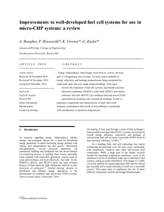
  • 1. ___ * Editors and peer reviewers. Improvements to well-developed fuel cell systems for use in micro-CHP systems: a review A. Baugher, P. Brussarski*, K. Fownes*, G. Zaylor* Advanced Writing, College of Engineering Northeastern University, Boston MA A R T I C L E I N F O A B S T R A C T Article history: Energy independence, from foregin fossil fuels as well as thelocal Received 20 November 2014 grid, is a burgeoining area of study. As such, various methods of Reviewed 24 November 2014 energy (electricity and heating) production are being researched for Accepted 5 December 2014 small-scale grids and even single homes/dwellings. This paper reviews the utilization of fuel cell systems, specifically polymer- Keywords: electrolyte membrane (PEMFC), solid oxide (SOFC), and molten Fuel cell system carbonate fuel cells (MCFC), for combined heat and power (CHP) Micro-CHP applications in residences and commercial buildings. It aims to Steam reformation emphasize components and characteristics of each that would Bipolar plates maximize performance and overall system efficiency, specifically Catalyst poisoning with consideration to operation temperatures. 1. Introduction As concerns regarding energy independence, climate change, and ecological impact rise, a need for distributed energy generation to match increasing energy demand with relative grid independence has also grown.1 Distributed microgeneration, on-site electrical generation for commercial building and residential use, has shown limited yet promising success in tackling these issues, especially when coupled with renewable generation sources such as wind, photovoltaics, and most effectively, fuel cells. So far, PEMFCs, SOFCs, and MCFCs show the most promise because of their relatively high efficiencies and low to zero emissions of pollutants.1,2 Another exciting advance in distributed and efficient energy generation is the development of combined heat and power (CHP) systems. These systems utilize “waste heat” from the heating of fuel, and through a series of heat exchangers heats potablewater and other HVAC systems, increasing the overall energy efficiency (electricity and heating) of conventional fuel cell systems to upwards of 80% from its lone electrical efficiency of 40%.3,4 As a budding field, fuel cell technology has shown widespread development over the past years, particularly with membranes, catalysts and other sub-system level components. While a large part of the debate revolves around the operating temperature conditions, some of the emphasis is on novel membrane make-ups or alternative fuel sources, seeing as steam reformation of hydrogen is a viable yet costly method for supplyingproper fuel, and the natural gas typically fed to steam reformers is itself not a renewable source.5 This paper aims to emphasize the role of these different components and the advantages/disadvantages
  • 2. 2 Figure 1: Diagram of typical PEMFC configuration6 inherent in their use, hopefully demonstrating how to maximize efficiencies and create a vastly improved system for electrical and heat generation located on-site. 2. System structure Fuel cell systems areall similar in therespect that they utilize fuels to generate electricity through reduction-oxidation reactions at anodes and cathodes via oxygen or another oxidizing reagent, as is evident in Figure 1. The large difference usually arises in thespecifichalf reactions that are taking place and thus the composition of the membrane that will act as the catalyst to the reaction. This in turn largely affects theoperating temperatureand other chemical kinetics factors that may improve or hinder the overall electrical potential of the system. Because of their commercial availability and overall preparedness for implementation, PEMFCs, SOFCs, and MCFCs are further reviewed. 2.1. PEMFCs Polymer electrolytemembrane fuel cells are by far the most researched and hence developed fuel cell systems on the market today, mostly because of their quick start-up and rapid responseto load changes for more robust applications.7 As is evident in Table1, PEMFCs arefed with hydrogen fuel and air to create the two half reactions seen at cathode/anode. They are typically operated at lower temperatures (60-140°C), but this again is a specific consideration in the case of CHP systems. 2.2. SOFCs Solid oxide fuel cells, while completing the same overall reaction, utilize their zirconia-based oxide ions as the main electron carrier, migrating across the electrolyte material to react with hydrogen gas or even carbon monoxide to produce thecorresponding chemical byproducts, despitethepresence of pure hydrogen fuel as a competent electron exchanger.8 SOFCs, much like PEMFCs, can be run at different categories of operating temperatures: intermediate (IT) and high temperature (HT). It should also be noted that these terms are relative; the range for IT-SOFC operation is 550- 800°C compared to the HT-PEMFC range from 100-200°C. Table 1: Classification of fuel cells8 2.3. MCFCs Similar to both PEMFCs and SOFCs, molten carbonate fuel cells again producewater as a byproduct of feed gas and air. However, their electrolyteis made of amembrane composed of carbonate anions that are simultaneously broken down and reformed, releasing electrons to pass from the anode to the cathode through a separate load circuit and producing electricity. As is evident in Figure 1, molten carbonate fuel cells operatein therange of temperatures between PEMFCs and SOFCS (around 650°C). Intriguingly enough, MCFCs are incredibly “fuel flexible” and thus can run on a gambit
  • 3. 3 of feed gases, such as hydrogen, carbon monoxide, natural gas, propaneand even such components as marine diesel and landfill gas, just to demonstrate its applicable versatility.9 3. Advantages & Limitations To better gauge the overall impact each of these candidate systems would make in the CHP market, it’s beneficial first to consider each systems benefits and disadvantages. Here, points of contention in the research of each system are addressed. 3.1. PEMFCs: High or low temperature? As stated previously, many of today’s PEMFCs operateat a low temperature relative to alternative fuel cell structures8 , the reason being that the polymer conducting membrane supposedly reaches a maximum conductivity at the higher end of the low temperature PEMFC (LT-PEMFC) operating temperature spectrum.10 Unfortunately, the catalyst implemented in LT-PEMFCs is pure hydrogen, a very expensive and largely inaccessible fuel source.11 Also, it requires a very complex water management system, as evident in Figure 2. Because of the price and overall availability of “syngases”, high temperature PEMFCs (HT-PEMFCs) are becoming increasingly popular; they are able to reduce the adsorption rate of CO reformate gas onto the catalyst sites, which would otherwise poison the catalyst and damage the functionality of the fuel cell over time.4 However, thepower density while working at such high temperatures is decreased due to inefficient use of waste heat, and also requires substantial modifications to the membrane. Table 2: Temperature comparisons for PEMFCs LOW TEMP. PEMFC HIGH TEMP. PEMFC OPERATING TEMPERATURE 80-100 °C Up to 200 °C ELECTROLYTE Water-based Mineral acid-based PT LOADING 0.2-0.8mg/cm2 1.0-2.0 mg/cm2 CO TOLERANCE <50 parts per million 1 - 5 % by Volume OTHER IMPURITY TOLERANCE Low Higher POWER DENSITY Higher Lower COLD START? Yes No WATER MANAGEMENT Complex None It also appears some research has met in the middle to identify H2/air HT-PEMFCs as the most promising technology, because “rates of electrochemical kinetics are enhanced, water management and cooling is simplified, useful waste heat can be recovered, and lower quality reformed hydrogen may be used as the fuel.”7 3.2. Use of different PEMFC membranes The type of membrane used in the fuel cell is perhaps inherently thelargest area of research on PEMFCs. Modified PFSA (perfluorosulfonic acid) membranes are common in fuel cells that run on standard hydrogen fuel due to their great ionic/conductive properties and their mechanical and thermal stability under stress.12 Interestingly enough, the conductivity of PFSA membranes such as Nafion dramatically decreases when moving towards higher temperatures than 100 °C. Much headway has been made to modify these membranes and even replace them, such as the introduction of ionic liquid-based gel-type proton conducting membranes. Ionic liquids “possess unique properties, such as non-volatility, non-flammability, wide electrochemical windows, high ionic conductivity, and excellent thermal and chemical stability,”making them very attractive alternatives especially at high temperatures.13 On an even more novel level, nano-composite membranes are being applied to fuel cells operation on methanol to make up for high permeability and low conductivity of typicalPFSA membranes associated with higher temperatures.14 3.3. SOFC temperature considerations Intermediate temperature operation for SOFCs is nice because of the expanded availability of materials for use in that range, as well as cost-effective fabrication. It is also beneficial because of the natural reduction in direct internal reforming (DIR) reaction rate at lower temperatures, allowing the use of methane gas without a separate gas reformer while avoiding dangerous temperature gradients.15 On the other hand, Hawkes also notes that SOFC operation at intermediate temperatures experiences some very high ohmic losses (losses in resistivity due to the electrolyte and/or electrodes8 ), and as a result must undergo large structural changes to mitigate these losses. These changes include increasing the size of expensive bipolar plates (electrodes), and thus are disadvantageous. Also, while the temperaturegradients mentioned earlier have been reduced, they are still very much present and create a large constraint on current density, and thus power output.15 3.4. System tradeoffs (especially MCFCs) It is well established in the fuel cell community that the success of novel prototype systems as they are brought to market-level production is significantly hampered by the cost of expensive and sometimes unique cell components; perhaps nowhere is this more evident than with MCFCs. Manfred Bischoff believes the system is limited in commercialization not only by cost, but by the specially made (sometimes even by hand) modules and parts necessary to produce a well-functioning MCFC. In order to unlock the high CHP efficiency and fuel versatility associated with MCFCs, manufacturing for volume production must be vastly improved.9
  • 4. 4 4. Conclusions To come to any formal conclusion regarding themost energy efficient and cost-effective system and therefore the best system, we must derive conclusions about each systemon a case-by-case basis. It is apparent that each option of PEMFC has its own merits and drawbacks. However, themajor drawback to LT- PEMFCs is the procurement of pure hydrogen gas and the sheer lack of byproduct heat to boost overall system efficiency. As for HT-PEMFCs, not enough research has gone into their market implementation. While the promises of HT-PEMFCs in regards to hydrogen usage are very appealing, large amounts of research and general experience has gone into utilizing LT-PEMFCs currently. So until more research can be compiled regarding hydrogen at higher operating temperatures, the focus should be on creating the necessary hydrogen infrastructure and developing next-gen membranes while still working at low temperatures. If the hydrogen distribution systemwere to be developed rapidly, then most of the disadvantages of LT-PEMFCs disappear and the pure hydrogen LT-PEMFC becomes relatively advantageous given residences are not looking towards fuel cells for the primary source of water and building heating. Typical variants of PFSA membranes have proven themselves as a sturdy yet inexpensive staplein the PEMFC production scheme. However, better alternatives have been developed and are increasingly efficient, stable, and durable relative to the likes of Nafion and other PFSA membranes. While many novel ideas aim to replace thePFSA membrane for good, theseoptions are conceptual or even micro-scale at best, and are relatively expensive; in the meantime, modifications to existing PFSA membranes should be utilized for desired variations in fuel cell operating temperature, power density, water usage, etc. In summation, it would appear low temperature PEMFCs using modified PFSA membranes and on-site steam reformers or methane gas as a feed would be most effective in residential applications. A large consideration for homeowners and apartment leasees is theincurred capital cost of the system, and because of the widespread use and subsequent commercialization of the low temperature PEMFC, it is much less costly to run this systemthan more recently discovered and complex systems like SOFCs or MCFCs. While the system would only be viable as a supplement for heating because of its low thermal effluent, the electrical efficiency and output of these PEMFCs are perfect for residential-sized electrical loads and thus are the best candidate for residential energy production until advances in technology and commercialization of said technology can improve the cost-benefit tradeoffs of HT- PEMFCs and alternative membranes. PEMFCs were designed with small-load, mostly mobile applications in mind; commercial entities (like office buildings and local power plants) require more robust systems, such as SOFCS or MCFCs, capable of both responding to large electrical loads and offsetting large heating requirements, if not supplying all of it. SOFCS are tricky because operating at high temperature (around 1000 °C) is extremely hazardous in this case and exponentially more likely to cause fires, while operating at intermediate temperatures causes drastic losses in power output. MCFCs, on the other hand, are most efficient at relatively high temperature, and some infrastructure has even been developed to harness the heating potential of these specific fuel cells, like the HotModule.9 For these reasons, it would appear MCFCs operating at their regular conditions would be most advantageous in this commercial setting; granted, the parts are expensive and manufacturing schemes for MCFCs is weak to date, but thelarger entities owning these buildings and plants have the necessary resources to push demand up for these particular fuel cells and perhaps pave theroad to full commercialization. Thefuel cell industry has a lot of improvement ahead of them, but directing our efforts towards commercialization of these systems to ease energy dependence is of paramount importance. □ __________ I would like to acknowledge my peer editors, Prof. Akbari, and my peers (roommates) for helping shape this document into its best form.
  • 5. 5 References 1. Wang, Caisheng, and M.H. Nehrir. “Distributed Generation Applications of Fuel Cells.” In Power Systems Conference: Advanced Metering, Protection, Control, Communication, and Distributed Resources, 2006. PS ’06, 244–48, 2006. doi:10.1109/PSAMP.2006.285395. 2. Cockroft, Jeremy, and Nick Kelly. “A Comparative Assessment of Future Heat and Power Sources for the UK Domestic Sector.” Energy Conversion and Management 47, no. 15–16 (September 2006): 2349–60. doi:10.1016/j.enconman.2005.11.021. 3. Romero-Pascual, E., and J. Soler. “Modelling of an HTPEM-Based Micro-Combined Heat and Power Fuel Cell System with Methanol.”International Journal of Hydrogen Energy 39, no. 8 (March 6, 2014): 4053–59. doi:10.1016/j.ijhydene.2013.07.015. 4. Jannelli, Elio, Mariagiovanna Minutillo, and Alessandra Perna. “Analyzing Microcogeneration Systems Based on LT-PEMFC and HT-PEMFC by Energy Balances.” Applied Energy 108, no. 0 (August 2013): 82–91. doi:10.1016/j.apenergy.2013.02.067. 5. 5. Ferraro, M., F. Sergi, G. Brunaccini, G. Dispenza, L. Andaloro, and V. Antonucci. “Demonstration and Development of a Polymer ElectrolyteFuel Cell Systemfor Residential Use.” Journal of Power Sources, Scientific Advances in Fuel Cell Systems, 193, no. 1 (August 1, 2009): 342–48. doi:10.1016/j.jpowsour.2009.02.064. 6. "How Fuel Cells Work." FuelEconomy.gov. U.S. Department of Energy, 21 Nov. 2014. Web. <http://www.fueleconomy.gov/feg/fcv_PEM.shtml>. 7. Zhang, Jianlu, Zhong Xie, Jiujun Zhang, Yanghua Tang, Chaojie Song, Titichai Navessin, Zhiqing Shi, et al. “High Temperature PEM Fuel Cells.” Journal of Power Sources, Special issue including selected papers presented at the International Workshop on Molten Carbonate Fuel Cells and Related Science and Technology 2005 together with regular papers, 160, no. 2 (October 6, 2006): 872–91. doi:10.1016/j.jpowsour.2006.05.034. 8. Ramani, Vijay. “Fuel Cells.” The Electrochemical Society Interface. Spring 2006. 41. 9. Bischoff, Manfred. “Molten CarbonateFuel Cells: A High TemperatureFuel Cell on theEdge to Commercialization.” Journal of Power Sources, 160, no. 2 (October 6, 2006): 842–45. doi:10.1016/j.jpowsour.2006.04.118. 10. Thanganathan, Uma, and MasayukiNogami. “Synthesis of Mixed CompositeMembranes Based polymer/HPA:Electrochemical Performances on Low TemperaturePEMFCs.” Journal of Membrane Science 411–412, no. 0 (September 1, 2012): 109–16. doi:10.1016/j.memsci.2012.04.020. 11. Authayanun et al., “Hydrogen Production from Glycerol Steam Reforming for Low- and High-Temperature PEMFCs.” International Journal of Hydrogen Energy 36, no. 1 (January 2011): 267-275. doi:10.1016/j.ijhydene.2010.10.061 12. Mauritz, Kenneth A., and Robert B. Moore. “State of Understanding of Nafion.” Chemical Reviews 104, no. 10 (September 21, 2004): 4535–86. doi:10.1021/cr0207123. 13. “Polymer Electrolyte Membranes for Fuel Cells.pdf,” n.d. 14. Alberti, G., and M. Casciola. “CompositeMembranes for Medium-TemperaturePEM Fuel Cells.” Annual Review of Materials Research 33, no. 1 (2003): 129–54. doi:10.1146/annurev.matsci.33.022702.154702. 15. Hawkes, A. D., P. Aguiar, C. A. Hernandez-Aramburo, M. A. Leach, N. P. Brandon, T. C. Green, and C. S. Adjiman. “Techno- Economic Modelling of a Solid Oxide Fuel Cell Stack for Micro Combined Heat and Power.” Journal of Power Sources 156, no. 2 (June 1, 2006): 321–33. doi:10.1016/j.jpowsour.2005.05.076.