
Empfohlen
Weitere ähnliche Inhalte
Was ist angesagt?
Was ist angesagt? (17)
Andere mochten auch
Andere mochten auch (20)
Ähnlich wie Acuvim ii-series-brochure-1040 e1303
Ähnlich wie Acuvim ii-series-brochure-1040 e1303 (20)
Kürzlich hochgeladen
Kürzlich hochgeladen (20)
Acuvim ii-series-brochure-1040 e1303
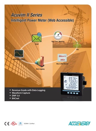
- 1. Data Logging Max & Min Record ISO9001 Certified Real Time Metering TOU Email Waveform Capture Acuvim II Series Intelligent Power Meter (Web Accessible) Revenue Grade with Data Logging Waveform Capture DNP 3.0 BACnet Max& Min
- 2. DESCRIPTION The Acuvim II series are high-end multifunction power and energy meters manufactured by Accuenergy. They are the ideal choice for the monitoring and controlling of power distribution systems. Some of the features and electrical power parameters available on the Acuvim II series are: • True-RMS Measuring Parameter • ANSI C12.20 (0.2 Class) and IEC 62053-22 (0.2S Class) • 16 MB Onboard Memory • Power Quality Analysis • Over/Under Limit Alarm • Multiple Communication Ports (E.g: Ethernet, RS485) • Supports Modbus RTU, DNP 3.0, BACnet IP, BACnet MS/TP • Web Server and Email Sending, SNMP, SNTP • Switch Status Monitoring • Waveform Capture • Measure Individual Harmonics from 2nd to 63rd Physical Anti-Tampering Seal 50/60Hz, 400Hz and 800Hz Rated Frequency Metering Modular Design Data Logging TOU, 4 Tariffs, 12 Seasons, 14 Schedules Class Leading Warranty The Acuvim II series may be used as data gathering devices for intelligent power distribution systems or plant automation systems. All monitored data is available via a digital RS485 communication port running Modbus RTU and DNP 3.0 protocols, additional communication options include: Ethernet, Profibus DP, and BACnet. With its flexible, modular I/O and communication options, the Acuvim II series is the most versatile and cost-effective metering solution on the market. CATEGORY ITEM Parameters Acuvim II Acuvim IIR Acuvim IIE Acuvim IIW METERING REAL TIME METERING Phase Voltage V1, V2, V3, Vlnavg Line Voltage V12, V23, V31, Vllavg Current I1, I2, I3, In, Iavg Power P1, P2, P3, Psum Reactive Power Q1, Q2, Q3, Qsum Apparent Power S1, S2, S3, Ssum Power Factor PF1, PF2, PF3, PF Frequency F Load Features Load Features Four Quadrant Powers Four Quadrant Powers ENERGY & DEMAND Energy Ep_imp, Ep_exp, Ep_total, Ep_net Reactive Energy Eq_imp, Eq_exp, Eq_total, Eq_net Apparent Energy Es Demand Dmd_P, Dmd_Q, Dmd_S, Dmd_I1, Dmd_I2, Dmd_I3 TOU TIME OF USE Energy/Max Demand TOU, 4 Tariffs, 12 Seasons, 14 Schedules DAYLIGHT SAVING TIME Two Adjustable Formats Month/Day/Hour/Minute Month/Week/First Few Weeks/Hour/Minute MONITORING Waveform Capture Voltage and Current Waveform Trigger, Manual, DI Change, Sag/Dips, Swell, Over Current POWER QUALITY Voltage Unbalance Factor U_unbl Current Unbalance Factor I_unbl Voltage THD THD_V1,THD_V2,THD_V3, THD_Vavg Current THD THD_I1, THD_I2, THD_I, THD_Iavg Individual Harmonics Harmonics 2nd to 63rd Voltage Crest Factor Crest Factor TIF THFF Current K Factor K Factor STATISTICS MAX with Time Stamp MIN with Time Stamp Each phase of V & l; Total of P, Q, S, PF & F; Demand of P,Q & S; Each phase THD of V & I; Unbalance factor of V & I OTHERS ALARM Over/Under Limit Alarm V, I, P, Q, S, PF, V_THD & I_THD Each Phase and Total or Average; Unbalance Factor of V & I; Load Type; Analog Input of Each Channel POWER QUALITY EVENT LOGGING Sag/Dips, Swell Voltage Data Logging Data Logging 1 Data Logging 2 Data Logging 3 F, V1/2/3/lnavg, V12/23/13/lavg, I1/2/3/n/avg, P1/2/3/sum, Q1/2/3/sum, S1/2/3/sum, PF1/2/3, PF, U_unbl, I_unbl, Load Type, Ep_imp, Ep_exp, Ep_total, Ep_net, Eq_imp, Eq_exp, Eq_ total, Eq_net, Es, THD_V1/2/3/avg, THD_I1/2/3/avg, Harmonics 2nd to 63rd , Crest Factor, THFF, K Factor, Sequence and Phase Angles, DI Counter, AI, AO, Dmd P/Q/S, Dmd I1/2/3 ONBOARD MEMORY SIZE Memory Bytes — 8MB 8MB 16MB COMMUNICATION RS485 Port, Half Duplex, Optical Isolated Modbus®-RTU Protocol/DNP3.0 Option TIME Real Time Clock Year, Month, Date, Hour, Minute, Second OPTION MODULE I/O OPTION Switch Status (DI) Digital Input (Wet) Power Supply for DI 24 Vdc Relay Output (RO) NO, Form A Digital Output (DO) Photo-MOS Pulse Output (PO) By Using DO Analog Input (AI) 0(4)~20mA, 0(1)~5V Analog Output (AO) 0(4)~20mA, 0(1)~5V COMMUNICATION Ethernet 10M/100M, Modbus-TCP, HTTP Webpage, Email Profibus-DP Profibus-DP/V0 BACnet IP or MS/TP RS485 Module Additional Modbus RTU Acuvim II Series Meters Function; Option; Blank NA
- 3. FEATURES Metering Voltage V1, V2, V3, Vlnavg, V12, V23, V31, Vllavg Current I1, I2, I3, In, Iavg Power P1, P2, P3, Psum Reactive Power Q1, Q2, Q3, Qsum Apparent Power S1, S2, S3, Ssum Frequency F Power Factor PF1, PF2, PF3, PF Energy Ep_imp, Ep_exp, Ep_total, Ep_net Reactive Energy Eq_imp, Eq_exp, Eq_total, Eq_net Apparent Energy Es Demand Dmd_P, Dmd_Q, Dmd_S, Dmd_I1, Dmd_I2, Dmd_I3 Load Features Four Quadrant Powers Monitoring Power Quality Voltage Harmonics 2nd to 63rd and THD Current Harmonics 2nd to 63rd and THD Voltage Crest Factor THFF (TIF) Current K Factor Voltage Unbalance Factor U_unbl Current Unbalance Factor I_unbl Max/Min Statistics with Time Stamps Alarms Limits can be set for up to 16 indicated parameters and can be set with a specified time interval. If any input of the indicated parameters is over or under its setting limit and persists over the specified time interval, the event will be recorded with time stamps and trigger the Alarm DO output. The 16 indicated parameters can be selected from any of the 51 parameters available. I/O option module The E-module® technique was adopted for its flexibility and easy expansion of the I/O function of Acuvim II. A maximum of 3 modules can be used for one meter. Digital input, digital output, pulse output, relay output, analog input and analog output are provided by I/O option module. Communication Modbus RTU Protocol and DNP 3.0 via RS485 Ethernet (Modbus TCP, HTTP, SMTP, SNMP, SNTP) Profibus DP BACnet IP, BACnet MS/TP Dual RS485 Communication Ports Module Name Spec AXM-NET 10M/100M Self-Adaptable, RJ45 Jack Modbus-TCP/IP Protocol HTTP Web Page Browser Email Sending on Time Interval or on Event AXM-PROFI Profibus-DP/V0 Input Byte (Typical): 32 Byte Output Byte (Typical): 32 Byte EN50170 Vol.2 Compliance Profibus Slave Mode, Baud Rate Self-Adaptable up to 12M Communication Module (Option) Display Clear and Large Character LCD Screen Display with White Backlight Wide Environmental Temperature Endurance Display Load Percentage, 4 Quadrant Powers, and Load Nature Outline Small Size 96×96 DIN or 4’’ANSI Round Data Logging Acuvim IIR/IIE/IIW offers 3 assignable historical logs where the majority of the metering parameters can be recorded. The onboard memory is up to 16 MB and each log size is adjustable. A real time clock allows for any logged events to be accurately time stamped. Time of use Users can assign up to 4 different tariffs (sharp, peak, valley and normal) to different time periods within a day according to the billing requirements. The Acuvim IIE meter will calculate and accumulate energy to different tariffs according to the meter’s internal clock timing and TOU settings. Waveform Capture Acuvim IIW can record 100 groups of voltage and current waveforms. It provides the waveform record of 10 cycles before and after the triggering point. It also supports a settable triggering condition. Power Quality Event Logging When a power quality event happens, such as voltage sag and swell, etc., Acuvim IIW will record the timestamp and the triggering condition of the event. It can save up to 50, 000 power quality events. Automatic Frequency adaptation Rated frequency is adjusted automatically to local frequency such as 50Hz or 60Hz. The same meter can be used in countries with different electrical frequencies. Flexible Current Input Compatible with different current transformers such as 5A, 1A, 80mA, 100mA, 200mA, 333mV output CT and Rogowski coil all available from Accuenergy. Module Name Spec AXM-RS485 Modbus®-RTU Protocol AXM-BMS BACnet MS/TP (Serial) AXM-BIP BACnet IP (Ethernet) APPLICATIONS Module Name Digital Input (DI) Power Supply For DI (24V) Digital Output (DO) Relay Output (RO) Analog Input (AI) Analog Output (AO) AXM-IO1 6 1 2 AXM-IO2 4 2 2 AXM-IO3 4 2 2 I/O Module (Option) Metering of Distribution Feeders, Transformers, Generators, Capacitor Banks and Motors Medium and Low Voltage Systems Commercial, Industrial, Utility Power Quality Analysis Data Logging
- 4. TYPICAL WEB PAGE FROM Acuvim II SERIES DATA LOGGING FROM Acuvim II SERIES Data LoggingMax & Min Record Alarm Record SOE Record Harmonics multi-platform access Built-in web server provides computer, tablet and smartphone access. Anti-tampering Seal: Users can physically seal the meter similar to a utility meter in order to provide anti-tampering protection. All metrological programming and user-defined parameters are protected with a physical seal. High Frequency Metering: Designed for use with 400Hz aircraft systems and 800Hz aerospace systems Acuvim II series power meters effectively monitors any airborne system.
- 5. Rogowski Coil Accuenergy's flexible Rogowski coil is designed for use where regular solid or split core current transformers cannot fit, and is ideal for power quality monitoring such as harmonics. Advantages of the Rogowski coil include; high accuracy, wide measurement and frequency range with no additional integrator or power supply needed. Dimensions mm (Inch) RCT16 RCT24 RCT36 RCT47 Window Size 106 (4.17'') 178 (7.01'') 271 (10.67'') 369 (14.53'') Coil Length 400mm (15.75'') 600mm (23.62'') 900mm (35.43'') 1200mm (47.24'') External Diameter 143 (5.63'') 207 (8.13'') 302 (11.89'') 398 (15.66'') Coil Diameter 15.5 (0.61'') Wire Lead Length 2 meters (6.5 feet) Specification Window Size Length of Coil 106mm (4.17''), 178mm (7.01''), 271mm (10.67''), 369mm (14.53'') 400mm (15.75''), 600mm (23.62''), 900mm (35.43''), 1200mm (47.24'') Current Input Ranges* Frequency Range Accuracy Lead 5A-1200A 12.5A-3000A 25A-6000A 50A-12000A 250A-50000A 20Hz - 5kHz 0.5% at any point White-Positive,Brown-Negative,Bare-Shield;24AWG Polarity Arrow Towards Load (Current Flow Direction) Operating Tempreture -20°C - 70°C Temperature Drift +/- 0.07% Within Operating Temperature Range Material OrangeThermoplastic Rubber, Flame Retardant UL 94 V-0 Rated Dielectric Strength 7400Vac @ 50/60Hz for 1 Minute Window Size External Diameter Coil Length Wire Lead Length 2 meters (6.5 feet) Coil Diameter 15.5 (0.61'') Unit : mm (inches) *Note: Listed ranges are standard input ranges, for any other current input ranges please contact Accuenergy.
- 6. Split core CTs 89.00mm (3.50'') 21.00mm (0.83") 31.00mm(1.22") 105.00mm(4.13") 40.00mm (1.57'') 51.00mm (2.00'') 50.00mm(1.97'') Unit : mm (inches) 114.00mm (4.49'') 50.00mm (1.97'') 80.00mm(3.15'') 145.00mm(5.71'') 50.00mm (1.97'') 78.00mm (3.07'') 50.00mm(1.97'') 144.00mm (5.67'') 80.00mm (3.15'') 120.00mm(4.72'') 185.00mm(7.28'') 50.00mm (1.97'') 108.00mm (4.25'') 50.00mm(1.97'') Unit : mm (inches) 176.00mm (6.93'') 80.00mm (3.15'') 160.00mm(6.30'') 247.00mm(9.72'') 70.00mm (2.76'') 120.00mm (4.72'') 50.00mm(1.97'') Unit : mm (inches) Unit : mm (inches)AcuCT-0812 AcuCT-2031 AcuCT-3147 AcuCT-3163
- 7. I/O OPTION Digital Input Input Voltage Range Input Current (Max) Start Voltage Stop Voltage Pulse Frequency (Max) SOE Resolution 20~160 Vac/dc 2mA 15V 5V 100Hz, 50% Duty Ratio (5ms ON and 5ms OFF) 2ms Digital Output (DO) (Photo-MOS) Voltage Range Load Current Output Frequency Isolation Voltage 0~250Vac/dc 100mA (Max) 25Hz, 50% Duty Ratio (20ms ON, 20ms OFF) 2500Vac Relay Output (RO) Switching Voltage (Max) Load Current Set Time Contact Resistance Isolation Voltage Mechanical Life 250Vac, 30Vdc 5A(R), 2A(L) 10ms (Max) 30mΩ (Max) 2500Vac 1.5x10⁷ Analog Output (AO) Output Range Accuracy Temperature Drift Isolation Voltage Open Circuit Voltage 0~5V/1~5V, 0~20mA/4~20mA (Optional) 0.5% 50ppm/°C Typical 500Vdc 15V Analog Input (AI) Input Range Accuracy Temperature Drift Isolation Voltage 0~5V/1~5V, 0~20mA/4~20mA (Optional) 0.2% 50ppm/°C Typical 500Vdc Power Supply for DI (24Vdc) Output Voltage Output Current Load (Max) 24Vdc 42mA 21 DIs METERING Parameters Accuracy Resolution Range Voltage 0.2% 0.1V 20V~1000kV Current 0.2% 0.1mA 5mA~50000A Power 0.2% 1W -9999MW~9999MW Reactive Power 0.2% 1var -9999Mvar~9999Mvar Apparent Power 0.2% 1VA 0~9999MVA Power Demand 0.2% 1W -9999MW~9999MW Reactive Power Demand 0.2% 1var -9999Mvar~9999Mvar Apparent Power Demand 0.2% 1VA 0~9999MVA Power Factor 0.2% 0.001 -1.000~1.000 Frequency 0.2% 0.01Hz 45.00~65.00Hz Energy Primary 0.2% 0.1kWh 0-99999999.9kWh Secondary 0.2% 0.001kWh 0-999999.999kWh Reactive Energy Primary 0.2% 0.1kvarh 0-99999999.9kvarh Secondary 0.2% 0.001kvarh 0-999999.999kvarh Apparent Energy Primary 0.2% 0.1kVAh 0-99999999.9kVAh Secondary 0.2% 0.001kVAh 0-999999.999kVAh Harmonics 1.0% 0.1% Phase Angle 2.0% 0.1° 0.0°~359.9° Unbalance Factor 2.0% 0.1% 0.0%~100.0% Running Time 0.01h 0~9999999.99h COMMUNICATION RS-485 (Standard) MODBUS® RTU and DNP 3.0 2Wire ShieldedTwisted Pair Cable Connection Baud Rate:1200~38400 bps The Second RS-485 Port (Optional) (The Same as RS-485 Standard Contents) Baud Rate: 4800~38400 bps Ethernet (Optional) 10M/100M BaseT MODBUS® TCP, SNMP, SNTP, HTTP Push Webpage Data Browsing Through HTTP Send email Based on Timer or Triggered Event PROFIBUS (Optional) PROFIBUS-DP/V0 Protocol Work as PROFIBUS Slave, Baud Rate Adaptive, up to 12M Typical Input Bytes: 32, Typical Output Bytes: 32 PROFIBUS Standard According to EN 50170 Vol.2 BACnet(Optional) BACnet lP, BACnet MS/TP INPUT Current Inputs (Each Channel) Nominal Current 5A /1A Metering Range 0~10A ac/0~2A ac Withstand 20Arms Continuous, 100Arms for 1 second, Non-Recurring Burden 0.05VA (Typical) @ 5Arms Pickup Current 0.1% of Nominal Accuracy 0.2% Full Scale Voltage Inputs (Each Channel) Nominal Full Scale 400Vac L-N, 690Vac L-L (+20%) Withstand 1500Vac Continuous 2500Vac, 50/60Hz for 1 Minute Input Impedance 2Mohm per Phase Metering Frequency 45Hz~65Hz Pickup Voltage 10Vac Accuracy 0.2% Full Scale Energy Accuracy Active (According to IEC 62053-22) Class 0.2s (According to ANSI C12.20) Class 0.2s Reactive (According to IEC 62053-23) Class 2 Harmonic Resolution Metered Value 63rd Harmonic SPECIFICATIONS CONTROL POWER Universal AC or DC AC/DC Control Power Operating Range 100~415Vac, 50/60Hz; 100~300Vdc Burden 5W Frequency 50/60Hz Withstand 3250Vac, 50/60Hz for 1 minute Installation Category III (Distribution) Low Voltage DC Control Power (Optional) Operating Range 20~60Vdc Burden 5W STANDARD COMPLIANCE Measurement Standard IEC 62053-22; ANSI C12.20 Environmental Standard IEC 60068-2 Safety Standard IEC 61010-1, UL 61010-1, IEC 61557-12 EMC Standard IEC 61000-4/-2-3-4-5-6-8-11, CISPR 22, IEC 61000-3-2, IEC 61000-6-2/4 Outlines Standard DIN 43700, ANSI C39.1 OPERATING ENVIRONMENT Operation Temperature - 25°C to 70°C Storage Temperature - 40°C to 85°C Relative Humidity 5% to 95% Non-Condensing
- 8. TYPICAL WIRING Single Phase 2 Wire (1LN, 1CT) Terminal Block A N LINE 1A FUSE LOAD I11 I12 I21 I22 I31 I32 VN V3 V2 V1 Acuvim II 3 Phase 4 Wire (3LN, 3CT) Terminal Block A B C N LINE 1A FUSE LOAD I11 I12 I21 I22 I31 I32 VN V3 V2 V1 Acuvim II Terminal Block A B C LINE 1A FUSE LOAD I11 I12 I21 I22 I31 I32 VN V3 V2 V1 Acuvim II Relay Output (RO) Wiring Energy Output (DO) Wiring N GL 220Vac comV+RO1 ROC DOC DOC DO1 DO2 OUT V+ COM 10K Power Supply Relay Control DO Type Pulse Output Alarm Output Buzzer 3 Phase 3 Wire (3LL, 3CT) Terminal Block A B C LINE 1A FUSE LOAD I11 I12 I21 I22 I31 I32 VN V3 V2 V1 Acuvim II Terminal Block LOAD I11 I12 I21 I22 I31 I32 VN V3 V2 V1 Acuvim II 3 Phase 4 Wire with PT (3LN, 3CT) Single Phase 3 Wire (1LL, 2CT) Terminal Block A N B LINE 1A FUSE LOAD I11 I12 I21 I22 I31 I32 VN V3 V2 V1 Acuvim II AXM-IO1 DI1 DI2 DI3 DI4 DI5 DI6 DIC RO1 RO2 ROC V+ V- Digital Input Digital Output VDC + + -- QF1 QF2 QF3 QF4 QF5 QF6 AXM-IO2/IO3 DI1 DI2 DI3 DI4 DIC Digital Input + QF1 QF2 QF3 QF4 QF5 - 20-160Vac/dc 3 Phase 3 Wire with PT and 2 CT(2LL, 3CT)* A B C D LINE 1A FUSE *Note: 2CT configuration is optional only in 3 Phase 3 Wire system.
- 9. I/O Module Dimensions Communication Module Dimensions 55.60(2.189) 90.00 (3.543) 19.50 (0.768) 55.60(2.189) 90.00 (3.543) 22.00 (0.866) Unit : mm (inches) Note: the 1 display module is connected with the body length of 2 meters, such as the need for a longer line, please order statement; 96.00(3.800) 96.00 (3.800) 91.00(3.583) 35.90 50.70 (1.996) 14.00 38.00(1.496) 7.60 (0.300) Rear View Side View DIN Mount Meter Dimensions External Display Module DimensionsUnit : mm (inches) Unit : mm (inches) 91.00(3.583) 35.90 (1.413) 10.00 (0.393)96.00(3.800) 96.00 (3.800) H P E V/A Multifunction Power Meter Front View Side View (1.413) (0.551) Note: 1. Display module is connected with a six foot 10 pin RJ45 cable, if you need a longer cable please specify that in the ordering statement. 2. Display module opening size and Acuvim II body openings are exactly the same size. BACnet Module Dimensions 14.75 (0.581) 11.75 (0.463) 65.57(2.581) 89.20 (3.512) 57.89 (2.279) DIMENSIONS Side ViewFront View Acuvim II Dimensions 91.00(3.583) 35.90 96.00(3.800) 96.00 (3.800) H P E V/A Multifunction Power Meter 102.00 (4.016) Cut-Out 92.00(3.622) 92.00 (3.622) Cut-Out Unit : mm (inches) (1.413) 50.70 (1.996) Cut Out
- 10. Note: 1. Accuenergy suggests using USB-RS485 converter for configuration, and 3 CTs per three phase circuits. 2. All fields must be completed to create a part number. 3. Add“-S”after power supply for anti-tampering seal option. 4. Contact Accuenergy for 400Hz and 800Hz frequency option. ORDERING INFORMATION Model Mounting Option Current Input Power Supply Ordering Number Ordering Example Acuvim IIE - D - 5A - P1 Acuvim II: Basic Model D: Intergrated with LCD Display (Panel Mount Meter/Transducer) 5A: 5A Input P1: 100~415Vac, 50/60Hz 100~300Vdc Acuvim IIR: II + Data Logging M: Din-Rail Mount Transducer without Display (Optional Remote Display Available) 1A: 1A Input P2: 20~60Vdc Acuvim IIE: IIR + Time of Use 80mA: 80mA Input Acuvim IIW: IIR + Waveform Capture and PQ Event Logging 100mA: 100mA Input 200mA: 200mA Input RCT: Rogowski Coil Input (Coil to be Ordered Feparately from Below) 333: 333mV Input Communication Option Module I/O Option module Note: 1. No more than 2 of the same I/O modules may be attached to the meter (example: Two AXM-IO2). The same two I/O modules must have a different logic number. 2. A maximum of 3 modules may be attached to the meter. If a communication module is used (example: AXM-NET), it must be installed on the back FIRST before the other modules are attached. 3. If Acuvim IIW uses DI to trigger a waveform capture, the I/O module logic number must be Module 1. AXM-IO1 A: 4~20mA B: 0~20mA C: 1~5V D: 0~5V Logic Module 1 AXM-IO2 Analog Output Type A: 4~20mA B: 0~20mA C: 1~5V D: 0~5V Analog Output Type 2 1 2 1 A: 4~20mA B: 0~20mA C: 1~5V D: 0~5V AXM-IO3 Analog Input Type A: 4~20mA B: 0~20mA C: 1~5V D: 0~5V Analog Input Type 2 1 I/O Module Ordering Example: AXM-IO2-1A AXM- PROFI: Profibus Module (AXM-PROFI) NET: Ethernet Module (AXM-NET) NET-P: Ethernet Module With HTTP Push Function AXM- BIP: BACnet lP (Ethernet) BMS: BACnet MS/TP (serial) RS485: Modbus®-RTU (AXM-RS485) Remote Display Option REM- DS2: Compatible with Acuvim II Series "M" (DIN Mount) Models Only Rogowski Coil Ordering Information: Note:1. Make sure maximum current rating in system being metered is within the current metering range for Rogowski coil. 2. Please contact Accuenergy if other lengths of coil or current ranges are needed. Size Current Range Ordering Number Ordering Example RCT16 1000 RCT16 : 15.75’’Coil, 4’’Diameter 1000: Metering Range 5A to 1200A RCT24 : 23.62’’Coil, 7’’Diameter 2500: Metering Range 12.5A to 3000A RCT36: 35.43”Coil, 10.67’’Diameter 5000: Metering Range 25A to 6000A RCT47: 47.24”Coil, 14.5’’Diameter 10000: Metering Range 50A to 12000A 50000: Metering Range 250A to 50000A Logic Module 2 Logic Module 1 Logic Module 2 Logic Module 1 Logic Module 2
- 11. Accuenergy Corp. Los Angeles-Toronto-Beijing North America Toll Free: 1-877-721-8908 Web: www.accuenergy.com Email: marketing@accuenergy.com Revision Date: Nov., 2014 Document #1040E1303 Note: Please contact Accuenergy if CTs in other sizes and ratios are needed. Additional Accessories: Split Core CT Ordering Information: AcuPanel ordering information: AcuPanel 9014 (NEMA4 Indoor Panel) AcuPanel 9104X (NEMA4X Waterproof) AcuCT-0812 - 200 - 5 200: 200A 5: 5A Input 250: 250A 300: 300A 400: 400A AcuCT-2031 - 400 - 5 400: 400A 600: 600A 800: 800A 1000: 1000A AcuCT-3147 - 1000 - 5 1000: 1000A 1200: 1200A 1600: 1600A AcuCT-3163 - 2000 - 5 2000: 2000A 2500: 2500A 3000: 3000A 4000: 4000A 5000: 5000A Model Rated Input Ordering Number Ordering Example