The high-gradient magnetic separation process is a technique used in heavy industries, particularly steel mills, to extract magnetic particles from mixtures. The difficulty of separating the slightly magnetic particles from the nonmagnetic ones lies in the distribution of the magnetic field and the fineness of their class to be separated. A use of different separation matrix profile is implemented, making it possible to act on the value of the gradient of the inhomogeneous magnetic field. Different matrixes are tested and the results obtained experimentally allows to choose the most efficient matrix form in the operation of extraction which increased by 11% in magnetic fraction yield, 15% iron content and 17% of extraction degree relative to the John’s matrix. This matrix used is consistent with that cited in literatures. The separation technology used can extend its useful application to small particles from very weakly magnetic materials. Its exploitation will result in the method of reducing the degree of pollution and improvement the process of extraction of minerals that has an impact on the environment and on human health as a result a high level of extraction.
Cara Menggugurkan Sperma Yang Masuk Rahim Biyar Tidak Hamil
High-Gradient Magnetic Separation Method for Weakly Magnetic Particles: an Industrial Application
1. PACS numbers: 75.20.En, 81.05.Bx, 81.40.Rs, 85.70.Ay, 91.60.Pn
High-Gradient Magnetic Separation Method for Weakly
Magnetic Particles: an Industrial Application
Chouki Farsi, Salah Amroune, Mustafa Moussaoui*
,
Barhm Mohamad**
, and Houria Benkherbache
Pôle Universitaire de M’sila,
Laboratoire de Matériaux et Mécanique des Structures,
Université Mohamed Boudiaf de M’sila,
BP 166 M’sila 28000, Algérie
*
Université Ziane Achour de Djelfa,
BP 3117 Djelfa 17000, Algérie
**
Faculty of Mechanical Engineering and Informatics,
University of Miskolc,
H-3515 Miskolc, Hungary
The high-gradient magnetic separation process is a technique used in heavy
industries, particularly steel mills, to extract magnetic particles from mix-
tures. The difficulty of separating the slightly magnetic particles from the
nonmagnetic ones lies in the distribution of the magnetic field and the fine-
ness of their class to be separated. A use of different separation matrix pro-
file is implemented, making it possible to act on the value of the gradient of
the inhomogeneous magnetic field. Different matrixes are tested and the re-
sults obtained experimentally allows to choose the most efficient matrix form
in the operation of extraction which increased by 11% in magnetic fraction
yield, 15% iron content and 17% of extraction degree relative to the John’s
matrix. This matrix used is consistent with that cited in literatures. The sep-
aration technology used can extend its useful application to small particles
from very weakly magnetic materials. Its exploitation will result in the
method of reducing the degree of pollution and improvement the process of
extraction of minerals that has an impact on the environment and on human
Corresponding author: Chouki Farsi
E-mail: Chouki.farsi@univ-msila.dz
Citation: Chouki Farsi, Salah Amroune, Mustafa Moussaoui, Barhm Mohamad, and
Houria Benkherbache, High-Gradient Magnetic Separation Method for Weakly
Magnetic Particles: an Industrial Application, Metallofiz. Noveishie Tekhnol., 41,
No. 8: 1103–1119 (2019), DOI: 10.15407/mfint.41.08.1103.
Metallophysics and Advanced Technologies
Ìåòàëîôіç. íîâітні òåõíîë.
Metallofiz. Noveishie Tekhnol.
2019, vol. 41, No. 8, pp. 1103–1119
https://doi.org/10.15407/mfint.41.08.1103
Reprints available directly from the publisher
2019 G. V. Kurdyumov Institute for Metal Physics,
National Academy of Sciences of Ukraine
Published by license under
the G. V. Kurdyumov Institute for Metal Physics–
N.A.S. of Ukraine Publishers imprint.
Printed in Ukraine.
1103
2. 1104 Chouki FARSI, Salah AMROUNE, Mustafa MOUSSAOUI et al.
health as a result a high level of extraction.
Key words: magnetic matrix, high-gradient magnetic separation process
(HGMS), gradient of magnetic field, magnetic particles.
Високоградієнтний процес магнітного розділення — метод, який викори-
стовується у важкій промисловості, особливо в сталеливарному виробни-
цтві, для виділення магнітних частинок із сумішей. Складність відділен-
ня слабомагнітних частинок від немагнітних полягає в забезпеченні не-
обхідного розподілу магнітного поля та малих розмірах цих частинок.
Використовуються різні види розділових матриць, що дозволяє впливати
на величину градієнта неоднорідного магнітного поля. Різні матриці були
протестовані і експериментально отримані результати дозволили вибрати
найбільш ефективну форму матриці для вилучення частинок, що дозво-
ляє збільшити на 11% вихід магнітної фракції, на 15% вміст заліза і на
17% ступінь вилучення відносно матриці Джона. Використовувана мат-
риця відповідає описаній в цитованій літературі. Використана технологія
розділення дозволяє розширити її корисне застосування на випадок дріб-
них частинок дуже слабких магнітних матеріалів. Використання даної
технології дозволяє зменшити ступінь забруднення, поліпшує процес ви-
добутку корисних копалин, який впливає на навколишнє середовище і
здоров’я людини завдяки досягненню високого рівня екстрагування.
Ключові слова: магнітна матриця, високоградієнтний магнітний сепара-
тор, градієнт магнітного поля, магнітні частинки.
Высокоградиентный процесс магнитного разделения — метод, который
используется в тяжёлой промышленности, особенно в сталелитейном
производстве, для выделения магнитных частиц из смесей. Сложность
отделения слабомагнитных частиц от немагнитных заключается в обес-
печении необходимого распределения магнитного поля и малых размерах
этих частиц. Используются различные виды разделительных матриц,
позволяющих влиять на величину градиента неоднородного магнитного
поля. Различные матрицы были протестированы и экспериментально по-
лученные результаты позволили выбрать наиболее эффективную форму
матрицы для извлечения частиц, что позволяет увеличить на 11% выход
магнитной фракции, на 15% содержание железа и на 17% степень извле-
чения относительно матрицы Джона. Используемая матрица соответству-
ет описанной в цитируемой литературе. Использованная технология раз-
деления позволяет расширить её полезное применение на случай мелких
частиц очень слабых магнитных материалов. Использование данной тех-
нологии позволяет уменьшить степень загрязнения, улучшает процесс
добычи полезных ископаемых, который влияет на окружающую среду и
здоровье человека благодаря достижению высокого уровня извлечения.
Ключевые слова: магнитная матрица, высокоградиентный магнитный
сепаратор, градиент магнитного поля, магнитные частицы.
(Received October 2, 2018; in final version, May 12, 2019)
3. HIGH-GRADIENT MAGNETIC SEPARATION METHOD 1105
1. INTRODUCTION
Magnetic separation is a physical separation process that separates
materials according to their magnetic susceptibility. Since the process
is based on physical rather than chemical properties, separations can
be achieved while producing a minimum of secondary waste. Magnetic
separation is a technique for removing scrap and concentrating iron
ores. Numerous works on magnetic separation have been addressed
published [1–3], which use describes various devices for mineral pro-
cessing. Conventional magnetic separation devices are generally lim-
ited to the separation of highly magnetic materials, such as iron and
magnetite. The provision of intense pulsed or fixed magnetic fields
(greater than 5 or 10 T) in laboratory is becoming more widespread and
the fields of application are increasing. The effects of intense magnetic
fields on matter are indeed many and sharpen the curiosity of re-
searchers. Quantum effects [2], thermodynamic [3], mechanical [4, 5]
imperceptible low field are observed in the material under strong mag-
netic field.
The industrial and environmental depollution treatment by magnet-
ic separation is used in the purification processes of the desulphurisa-
tion of the coals used as fuel in the furnaces of thermal and electrical
power plants. It involves reducing the ash and sulphide (FeS2) content
present in the coal mass. It is also used in the filtration of fluids in
thermal or nuclear power plants for the production of electrical energy
by extracting particular or corrosive products.
The development of the magnetic separation of the particles is based
on the improvement of the gradient of H field in [kA/m2
], where H is
the intensity of the magnetic field in [kA/m]. This method of filtration
of the pulp through layers of magnetic is used by several authors [6–
12]. Notably Turkenich et al. [13] has shown that the choice of pole
shapes plays a key role in obtaining a non-homogeneous magnetic field
with a maximum value of the gradient. This inhomogeneity and uni-
formity of the field ensures even more the opening of the magnetic
fraction. The latter helps the process of washing these magnetic frac-
tions which continues the separation process; this is explained by the
ease of penetration of water through the magnetic flocculates. This
wash removes non-magnetic particles that stick to magnetic ones. The
first filters were made by Turkenich et al. [13] in the form of steel
grids. These poles consist of rapid demagnetization metal plates made
of mild steel such as the cores of transformers are generally used at
high-gradient separators. Currently these separators consist of a ro-
tating part (rotor) where are placed the matrices of different profiles
which will be magnetized, and a fixed part (stator) which creates the
magnetic field with a very intense flux concentrated on the walls of the
matrices separations during the magnetization period. The essential
4. 1106 Chouki FARSI, Salah AMROUNE, Mustafa MOUSSAOUI et al.
feature of the high-gradient separation is the closure of the electro-
magnetic system, where a very high induction is created in the electro-
technical steel ring cores that pass through the small volume of work
through the dies. The selection of the shape and the dimensions of the
elements of the matrix of the separator depend on the intensity of the
field. With a relatively weak magnetic field separation can only be
achieved if a poly-gradient medium is used which can improve the level
of magnetic forces required for extraction. Virtually all types of high-
gradient matrices provide the required gradient magnetic field [14], so
their shape is necessary to select the magnetic particles on the basis of
mechanical properties and fluid flow regime. To obtain the level of
magnetic force necessary for the extraction, with a relatively weak
magnetic field it is necessary to use only a poly-gradient medium of the
field. The possibility of its regeneration must be given great im-
portance since the separation cycle is repeated each time. This regener-
ation can be explained by the rotation of the rotor which keeps the ma-
trices of the separator in continuous rotation by carrying out the four
operations at the same time, notably: the feeding of the separation ma-
trices by the pulp (water + product); magnetization of this product
found in matrices; washing the flocculants attracted and then glued to
the internal separation surface; the demagnetization of the magnetic
fraction. After this operation the separation cycle is repeated. A poly-
gradient medium may be as: metal wool; a set of corrugated plates ar-
ranged in parallel; a set of parallel metal rods; a volume filled with
metal balls.
On the one hand, it is necessary to increase the effective extraction
surface of the magnetic particles, and on the other hand—maximum
approximation of the radius of curvature of the elements of the extrac-
tion surface with respect to the particle size of the material recovered,
according to the results of the studies, directed by Karmazin [15], the
most effective dimensions of the particles that adhere on the magnetic
surfaces are of the class 0.04–0.05 mm, because these requirements
are the most compatible with the wire wool son of 0.1 mm thick, used in
poly-gradient separators (Sala separators, etc.) [15], however it has a
low filtration rate, is quickly clogged by inclusions and hard non-
magnetic salts. The experiments show that even for small values of the
strength of the magnetic field the metallic wool provides enough good
extraction of the highly magnetic particles of the pulp [16]. On the
other hand, the complex, the micro porous structure of the metal wool
does not favour the release and the passage of the pulp, and the wash-
ing of the magnetite particles in the industrial conditions which are
carried out under a large water pressure, which is expensive.
In addition, due to the constant reorientation of the magnetic field,
the particles which are in a relatively free state on the surface of the
accumulated layers acquire a rotating moment torque. When addition-
5. HIGH-GRADIENT MAGNETIC SEPARATION METHOD 1107
al water is supplied, with discharge rotation of sterile and weakly
magnetic particles becomes easy, which increases the quality of the
concentrate. The details and the description of this phenomenon of ro-
tation of the magnetic particles in the alternating magnetic field have
been described in Refs. [17, 18].
The work presented is concerned with the analysis of the distribu-
tion of the field within the separation space for the different matrices
used by a quantitative evaluation of the field gradient for each point
between the separation poles. The end goal is to use this method in the
steel mill of M’sila (Algeria) which produces iron from the products of
recovery.
2. EXPERIMENTAL MATERIAL AND PROCEDURES
The apparatus used for the realization of the matrices is a high-
gradient separator of the laboratory of the National University of
Kryvyi Rih (Ukraine), department of enrichment of useful minerals
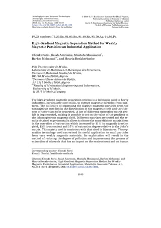
(Fig. 1). It consists of the coils of the separator of the laboratory (1); an
opening for the location of the dies between the poles of the magnetic
core (2); an outer core of the coils of the magnetic system for closures
of the magnetic flux (3) and a mechanism for clamping the dies inside
the magnetic poles (4).
There are five types of matrices used experimentally (Fig. 2) for
high-gradient separation with magnetized flocculants forms.
After several experiments on the magnetized bodies, for example
those represented on the Fig. 3, a–d. We arrived at the final forms pre-
sented in Fig. 4, a–c. For the convenience of measurements and for a
good distinction of the lines of the magnetic field we examined at the
a b
Fig. 1. High-gradient magnetic separator. Functional scheme (a), kinematic
scheme (b).
6. 1108 Chouki FARSI, Salah AMROUNE, Mustafa MOUSSAOUI et al.
beginning each group of teeth of different shapes in front poles of flat
shapes.
There are several forms of matrices used for the high-gradients sep-
arators of the field one was considered and selected those which pre-
sented in Fig. 4.
The working angle of the magnetic poles becomes effective in sepa-
ration if its value lies between 40–60°. According to the convenience
and ease of construction in the present work, the angle of these poles is
taken equal to 45° for each group of teeth. From the view from above
the distance between the measuring points is 5 mm, in both directions
to obtain the more or less exact gradient of the studied form.
Each selected matrix is introduced between the magnetic poles of the
two magnetization coils and this before their DC power supply, and
then the tightening is done by the screw system (Fig. 1, b) and this af-
ter positioning the dies between these poles of the separator.
The next step is the measurement of the magnetic induction for each
Fig. 2. Perspective view (a), views of the dies with the flocculates (b–e).
Fig. 3. Top views of the matrices used during the analysis of the magnetic
field. John’s matrices with opposite peaks facing each other (a), John’s ma-
trices with vertices of the North poles which are placed in front of the concave
parts of the other poles (b). Dies with 5 wide combined profiles for each tooth
period (c), 7 thin combed dies for each tooth period (d).
7. HIGH-GRADIENT MAGNETIC SEPARATION METHOD 1109
of the shapes used in front of the flat poles to simplify the measure-
ments sees Fig. 4. The magnetic induction measurement values are
taken successively from the points a, b, c, d, e, f, g to the points in
front which are a′, b′, c′, e′, f′, g′ squares of the grids drawn between the
different shapes of the poles as shown in the figures below Fig. 3.
After obtaining the values of the magnetic inductions by a Tesla-
meter, we computed the magnetic forces then the gradients of the field
of these forces and then plotted the curves of the gradients according
to the types and shapes of matrices.
3. THEORETICAL STUDY: CONCEPT OF THE MAGNETIC FIELD
It is clear that increasing the value of the magnetic field H will in-
crease the magnetic force both by increasing the magnetization of the
particle and, in general, by increasing the value of the field gradient.
However, it may be seen intuitively that the magnetic field gradient,
that is, the distance in which the magnetic field changes by a signifi-
cant amount will strongly affect the magnetic force.
In the case of a linear, homogeneous and isotropic material, the
magnetic volume energy of magnetization acquired by a particle is giv-
en by the following relation [19, 20]:
20
,
2
m H
mχ
ε =− (1)
where εm—magnetic energy magnetization [J/m3
], H—magnetic field,
χ—magnetic susceptibility [m3
/kg], m0—vacuum permeability [H/m].
The equation presented is a function of the term χ magnetic suscep-
tibility (MS), which translates the capacity of anybody to acquire mag-
netization induced under the effect of a magnetic field. So that’s the
report (M/H) with the magnetization M in [A/m], that is to say a field
Fig. 4. Matrices used in the analysis of the magnetic field: a—John’s matri-
ces, b—proposed triangular tooth matrices, c—matrices with combined pro-
files.
8. 1110 Chouki FARSI, Salah AMROUNE, Mustafa MOUSSAOUI et al.
involved in a solid angle, and the field (induced) H. For diamagnetic
materials, magnetic susceptibility χ is of the order of −10−5
and of 10−3
for paramagnetic substances, susceptibilities of up to 106
for ferro-
magnetic materials are even more noticeable.
There are several types of magnetism: when χ is negative, we say
that the body in which the magnetization appears is diamagnetic; when
χ is zero, there is a vacuum; when χ is positive, the body is called para-
magnetic; when χ is positive and very high, the paramagnetic body is
called ferromagnetic.
The force associated with the magnetic energy magnetization vol-
ume is derived from this energy by the relation [19, 20]:
,mv m= εf grad (2)
where εm magnetic energy magnetization [J/m3
], fmv is volume magnet-
ic force [N/m3
].
A particle always seeking to minimize its energy, its behaviour will
vary according to the nature of its magnetism: a paramagnetic particle
(χ > 0) will be attracted to intense fields while a diamagnetic particle
(χ < 0) will be drawn to the weak field areas.
The expression of the volume force can be obtained according to the
gradient of the magnetic field [19, 20]:
20
,
2
mv H
χm
=f grad (3)
where χ—magnetic susceptibility [m3
/kg], m0—vacuum permeability
[H/m], H—magnetic field [A/m].
Consider a spherical particle located in a field, along the axis of
symmetry and for values of applied magnetic field H0 less than the
bulk saturation value of the ferromagnetic wire Hs, the magnetic field
is given by the expression:
2
0 2
1 ,
a
H H
r
= +
(4)
where H0—magnetic field of middle [A/m], r is the center of the wire,
a is the radius of the wire (Fig. 5).
The magnetic field gradient for applied fields H0 less than H, along
the axis at the particle, is given by the expression:
2
0 3
2 ,
dH a
H
dr r
= − (5)
where H0 is induction of the magnetic field of middle [T], if the mag-
netization of the particle is small. The radius of the wire is a, the dis-
9. HIGH-GRADIENT MAGNETIC SEPARATION METHOD 1111
tance from the centre of the wire is r. These equations describe a fer-
romagnetic cylinder in an applied field H0.
We may now consider the dependence of the magnetic force on the
particle diameter for magnetic separators which are gradient-
matched, that is, in which the radius of the wire is equal to three times
the particle radius. In this case may be rewritten as:
2 2
01.84( ) ,m p mF H bχ χ= − (6)
where χp is a magnetic susceptibility of particle [m3
/kg], χm is magnetic
susceptibility of middle [m3
/kg], H0 is a magnetic field of middle
[A/m], b—radius of particle [m].
The forces in magnetic separators which compete with the magnetic
forces and act on all of the particles which travel through the separator
are those of gravity, hydrodynamic, drag, fraction, and inertia. We
will consider only gravitational and hydrodynamic drag forces which
are important in determining the characteristics of many magnetic
separators, including high-gradient devices. For spherical particle of
radius b and density of particle ρp the gravitational or buoyant force is
given by:
34
( ) ,
3
g p fF b g= p ρ − ρ (7)
where ρp is the density of the particle used in the separator, ρf is the
density of the fluid medium used in the separator, g is the gravitation-
al constant.
The hydrodynamic magnetic force is larger than either of the com-
Fig. 5. Cross section of spherical particle.
10. 1112 Chouki FARSI, Salah AMROUNE, Mustafa MOUSSAOUI et al.
peting forces, drag force is given by:
12 .dF b= πϑν (8)
In this relation ν is the kinematic viscosity of the fluid medium and ϑ is
the velocity of the particle relative to the stream and it applies in the
Stokes region. The dependence of the gravitational force on the third
power of the particle radius means that the gravitational force will be
significant for large particles. The hydrodynamic drag force, which in
the Stokes regime depends on the first power of the particle radius,
will be important for small particles. Thus in a magnetic separator
which treats large particles in dry form, the feed material might be
passed through the separator under the force of gravity.
The magnetic forces would have to be sufficient to hold the magnetic
particles against the competing force of gravity. In wet separator for
small particles the magnetic force would have to be larger than the hy-
drodynamic drag force which the slurry stream would exert on the
trapped particles.
4. RESULTS AND DISCUSSIONS
The measurements of the induction and the H-gradient calculations of
the field of the studied matrices showed us that these magnetic param-
eters weaken rapidly while moving towards the bottom of the teeth of
the magnetic poles. From the curves drawn from the gradient H we no-
tice that the maximum values are close to the vertices, (see Table 1 re-
sults), and going down to the flat pole the gradient decreases succes-
sively in the direction of the measurement points a′ → a, b′ → b, c′ → c,
g′ → g, to the angle that connects the two groups of teeth. This is ex-
plained by the increase in the distance of the curvatures of the force
lines between these poles where we distinguish the distribution with
more freedom. The equipotential lines of the magnetic forces coming
out of the surfaces and focusing perpendicularly are usually concen-
trated on the vertices of the poles. For the creation of good conditions
for obtaining maximum values of the magnetic force gradient H, it is
necessary to use for the matrices profiles or groups of convex teeth are
in faces of those concaves. By this way one obtains the two convex and
concave parts face to face of each pole where it is necessary that the ax-
is of symmetry of the convexity of one of the poles is confounded with
the bisector of the angle of the concavity of the other pole. For the im-
provement of the technology of preparations of these forms it is suffi-
cient only to take the top in angular form and the other teeth on the
lateral plane of flat shapes. The essential method of finding the opti-
mal form of fast demagnetization cores is that of mathematical model-
ling with programs and software for the different possible forms of
11. HIGH-GRADIENT MAGNETIC SEPARATION METHOD 1113
equipotential lines such as Solid Works or CATIA.
The analysis of the phenomenon of concentration of the field which
is at the top of teeth. It is also explained by the tendency of these
curved lines to those directed towards the nearest surface perpendicu-
larly. Thanks to the openings between the magnetic particles, the qual-
ity of the product extracted after the washing process is better and
cleaner and the washing is very convenient to achieve. For a good dis-
tinction between the qualities of the magnetic fractions obtained we
chose the size classes for our experiments (Fig. 6). Depending on the
size, the residues are separated by particle size class (with a particle
diameter less than 0.1 mm with an amount less than 75%) and pow-
dery.
The variation of the characteristics of the magnetic field with re-
spect to the shapes of a tooth of acute poles of different angles of work.
It can be seen that with the reduction of the working angle of the tooth,
the in homogeneity of the field increases, which causes the increase of
the force. The magnetic forces acting on the materials are generally
very low for paramagnetic materials or diamagnetic. These forces de-
rive from a volume magnetic energy acquired by the material in the
presence of an applied magnetic field.
The material is said to be diamagnetic when the atomic or molecular
layers are saturated, the resulting magnetic moment is zero. These ma-
terials nevertheless have a magnetic effect when subjected to a mag-
Fig. 6. Matrices used in the analysis of the magnetic field: a—John’s matri-
ces, b—proposed triangular tooth matrices, c—matrices with combined pro-
files.
12. 1114 Chouki FARSI, Salah AMROUNE, Mustafa MOUSSAOUI et al.
netic field: they will be pushed back by an intense field.
The electronic orbits are modified under the effect of the applied
TABLE 1. Influence of pole shapes on the parameters of the magnetic field
following the change in the distance between the poles.
a—John’s matrices.
X
In the direction of the point (mm)
B, T H, kA/m
gradH⋅103
kA/m2
5 a to a′ 0.133 105 0.636
10 b to b′ 0.129 102 1.432
15 c to c′ 0.120 95 1.909
20 d to d′ 0.108 85 1.591
25 e to e′ 0.098 77 0.795
30 f to f′ 0.093 74 0.750
35 g to g′ 0.082 65 0.636
b—proposed triangular tooth matrices.
X
In the direction of the point (mm)
B, T H, kA/m
gradH⋅103
kA/m2
5 a to a′ 0.105 83 0.795
10 b to b′ 0.110 87 1.273
15 c to c′ 0.102 81 1.909
20 d to d′ 0.090 71 3.183
25 e to e′ 0.070 55 0.795
30 f to f′ 0.065 51 2.387
35 g to g′ 0.050 39 0.954
c—matrices with combined profiles.
X
In the direction of the point (mm)
B, T H, kA/m
gradH⋅103
,
kA/m2
5 a to a′ 0.170 135 –
10 b to b′ 0.180 143 1.591
15 c to c′ 0.150 119 4.774
20 d to d′ 0.120 95 4.774
25 e to e′ 0.105 83 2.387
30 f to f′ 0.082 65 3.660
X is the distance from the pole of the South acute matrix to the North Pole;
B—induction of the magnetic field; H—intensity of magnetic field.
13. HIGH-GRADIENT MAGNETIC SEPARATION METHOD 1115
magnetic field, and a magnetic moment is induced parallel to the ap-
plied field, in opposite directions, with a modulus proportional to the
magnetic excitation. In the case where the atom has an incomplete elec-
tronic layer, it has a non-zero magnetic moment. When the thermal
energy is stronger than the interaction energy of these magnetic mo-
ments, or when they do not interact with each other, the material is
called paramagnetic. In zero fields, the directions of the moments are
random, and the material does not have any resulting magnetization.
Figure 7 shows the evolution of the gradient of the field H, as a
function of the distance between the poles for the three types of ma-
trix. The matrix c has recorded a high gradient H for a short distance
between poles, which leads to a consumption of one more energy, as the
distance increases the energy, tends towards a decrease for the three
matrices. On the other hand, the matrix b gives us a weak gradient H
with respect to the others consequently less energy.
For the comparison of the technological indices of the magnetic sepa-
ration and the determination of the disadvantages and for the clarifica-
tion on the advantages of one type of matrix compared to another aim-
ing at the creation more or less of the same magnetic separation condi-
tions, we took for all types of matrix the same average magnetic induc-
tion between these poles. It is clear that because of the different shapes
of the poles and their arrangements, and because of the coefficient of
filling of the volume between the ferromagnetic poles, really, the mag-
netic potential and its induction more precisely will also be different.
Fig. 7. Maximum values of gradient H.
14. 1116 Chouki FARSI, Salah AMROUNE, Mustafa MOUSSAOUI et al.
TABLE 2.Comparison of the high-gradient magnetic separation results of dif-
ferent classes of hematite ore (Algerian) by the three matrices used the mag-
netic induction of work is of B = 1.0 T.
Matrice Indices
Classes (mm)
0.074 + 0.063
Classes (mm)
0.063 + 0.044
Classes
(mm)
0.044
Sum
Non-
magnetic
fraction
′Y0(initial) 37 27.6 35.4 100
β0(initial) 40 44.1 47.8 43.9
a John’s
′Y
β
ε
20.81
48.4
22.94
16.18
58.2
19.72
17.52
52.7
21.04
54.61
51.21
63.7
45.39
35.10
–
b
With tri-
angular
teeth (in
this work)
′Y
β
ε
21.75
49.6
24.57
17.2
53.6
21.00
18.29
52.9
22.03
57.24
91.8
67.60
42.76
33.33
–
c
Combined
profiles (in
this work)
′Y
β
ε
23.06
51.30
26.94
17.9
54.40
22.18
19.95
55.80
25.35
60.91
53.67
74.47
39.09
28.67
–
′Y—separation efficiency in %; β—iron content in %; ε—degrees of extrac-
tion in %.
TABLE 3. Comparison of the high-gradient magnetic separation results of
different classes of hematite ore (Algerian) by the three matrices used the
magnetic induction of work is of B = 1.5 T.
Matrice Indices
Classes (mm)
0.074 + 0.063
Classes (mm)
0.063 + 0.044
Classes
(mm)
0.044
Sum
Non-
magnetic
fraction
′Y0(initial) 37 27.6 35.4 100
β0(initial) 40 44.1 47.8 43.9
a John’s
′Y
β
ε
21.52
47.50
23.28
17.31
52.40
20.66
18.73
51.20
21.84
57.56
50.16
65.78
42.44
35.30
–
b
With trian-
gular teeth
(in this
work)
′Y
β
ɛ
21.75
48.30
23.93
17.68
52.60
21.18
19.26
51.20
22.46
58.69
50.54
67.57
41.31
34.46
–
c
Combined
profiles (in
this work)
′Y
β
ε
23.17
49.40
23.07
18.58
53.40
22.60
21.23
54.50
26.35
52.98
52.29
75.03
37.02
29.62
–
15. HIGH-GRADIENT MAGNETIC SEPARATION METHOD 1117
The experiments are conducted with a magnetic induction B between
the poles of equal value 1, 1.5, and 2 T.
The separating product was first grinded to the 0.074 mm class for
chemical analyses and the comparison of the magnetic enrichment ef-
ficiency of its different particle size classes (see Tables 2 and 3). The
results of the experiments show that for the matrix (b) with triangular
teeth in comparison with the matrix (a) of John’s, and also for the ma-
trix (c) with combined profiles in comparison also with the matrix (a)
of John’s, with an induction between the poles 1.5 T. The quality of the
magnetic fraction and the percentage of extraction in Iron for all the
classes are superior it is the expected result. This shows in more than
with the proposed matrix (c) the separation of the fine class (0.044
mm) gave a degree of extraction 5% greater compared to the John’s
matrix, which proves a high technological efficiency the use of the
proposed matrix.
The results of separation show (see Table 4) that with an upper in-
duction between the poles B = 2 T applied to the matrices and for all the
granulometric classes act according to the usual laws that is to say
with the increase of the induction the degree of iron extraction in-
creases, but the quality of the magnetic product decreases.
5. CONCLUSION
The series of tests applied to the different matrices in order to improve
TABLE 4. Comparison of the high-gradient magnetic separation results of
different classes of hematite ore (Algerian) by the three matrices used. The
magnetic induction of work is of B = 2.0 T.
Matrice Indices
Classes (mm)
0.074 + 0.063
Classes (mm)
0.063 + 0.044
Classes
(mm)
0.044
Sum
Non-
magnetic
fraction
′Y0(initial) 37 27.6 35.4 100
β0(initial) 40 44.1 47.8 43.9
a John’s
′Y
β
ε
21.47
47.10
23.03
17.34
51.7
20.42
19.67
50.6
22.57
58.48
49.64
66.12
41.52
35.81
–
b
With trian-
gular teeth
(in this
work)
′Y
β
ε
21.56
47.10
23.13
17.9
52.2
21.28
19.98
51.0
28.21
59.44
49.94
67.62
40.56
35.04
–
c
Combined
profiles (in
this work)
′Y
β
ε
23.25
49.2
26.05
19.14
53.2
23.1
22.16
54.3
28.21
64.55
52.12
67.62
35.45
28.93
–
16. 1118 Chouki FARSI, Salah AMROUNE, Mustafa MOUSSAOUI et al.
the efficiency of the extraction of ores, we used three types of matri-
ces—John’s matrices, proposed matrices with triangular teeth and
Matrices with combined profiles.
The study conducted is based on the use of the method of high-
gradient magnetic separation for weakly magnetic particles. The ac-
tion provided on the profile of the matrices consequently leads to
changes in the separation distance which causes a variation in the in-
tensity of the gradient of the magnetic field. The opted shape of the
matrices, which is the matrix with triangular teeth a, makes it possible
to give better results of one side of improvement of the intensity of the
magnetic field gradient as a result, a finer extraction of the particles
on the other side to increase the rate of extraction for varieties of par-
ticle sizes and shapes. The findings that we have detected on the choice
of this type of matrix are as follows.
– Magnetic forces at the top of the matrix that is not optimal since
there are large concentrations of field. But for the lateral parts of
teeth, the field lines come out of the lower surfaces where the space
remains empty devoid of magnetic floccules during the separation. It is
for this reason that the gradient H to decrease rapidly while going
down the teeth and the area of distribution of the field to decrease.
– With the decrease of the angle of the acute pole, the in homogenei-
ty of the field increases, which causes the increase of the gradient of
the field.
– The combined forms for the creation of good conditions for obtain-
ing maximum values of the magnetic force ~HgradH. Just as it is nec-
essary to use profiles of the matrix where the groups of convex teeth
are in front of those concave, as the compound of sharp, flat teeth.
– For the improvement of the technology of preparations of these
forms it is enough only to take the top in triangular form and the other
teeth on the lateral plane of flat shapes.
Finally, the process in this method finds its extension to the resolu-
tions of the magnetic separation problems for the decontamination of
the grounds and acts in a direct way on the environment following a
significant reduction of the external pollution rate and also a higher
rate of extraction of minerals.
ACKNOWLEDGEMENTS
The authors would like to thank Pr. Bahri Deghfel, Physics Depart-
ment, Faculty of Sciences, University of Mohamed Boudiaf, M’sila
(Algeria) for his help. He made a review and read this article. The au-
thors would also like to thank the engineers from the laboratory of
high-gradient magnetic field separation of the National University of
Kryvyi Rih (Ukraine) for the use of the materials.
17. HIGH-GRADIENT MAGNETIC SEPARATION METHOD 1119
REFERENCES
1. L. R. Avens, L. A. Worl, K. J. DeAguero, D. D. Padilla, F. C. Prenger,
W. F. Stewart, D. D. Hill, and T. L. Tolt, Abstr. Conf. Magnetic Separation for
Soil Decontamination (28 Feb–4 Mar, 1993, United States).
2. A. Matsuzaki and S. Nagakura, Journal of Luminescence, 12: 787 (1976).
3. T. Kakeshita, K. Shimizu, S. Funada, and M. Date, Acta Mater., 33, No. 8:
1381 (1985).
4. Y. Xu, J. Chen, B. Jiang, Y. Liu, and J. Ni, Int. J. Mech. Sci., 142: 86 (2018).
5. J. Torbet, J. M. Freyssinet, and G. Hudry-Clergeon, Nature, 289: 91 (1981).
6. W. Ge, A. Encinas, E. Araujo, and S. Song, Results Phys., 7: 4278 (2017).
7. S. Miltenyi, W. Müller, W. Weichel, and A. Radbruch, Cytom. A, 11, No. 2: 231
(1990).
8. C. T. Yavuz, J. T. Mayo, W. Y. William, A. Prakash, J. C. Falkner, S. Yean,
and D. Natelson, Science, 314 (5801): 964 (2006).
9. J. J. Hubbuch, D. B. Matthiesen, T. J. Hobley, and O. R. Thomas,
Bioseparation, 10: 99 (2001).
10. M. A. M. Gijs, Microfluid. Nanofluid., 1: 22 (2004).
11. J. Svoboda, and T. Fujita, Miner. Eng., 16: 785 (2003).
12. R. R. Dauer and E. H. Dunlop, Biotechnol. Bioeng., 37: 1021 (1991).
13. A. M. Turkenich, Physical Separation in Science and Engineering, 10: 207
(2001).
14. J. Svoboda, Miner. Eng., 14: 1493 (2001).
15. V. Karmazin, Magnitnye, Elektricheskie i Spetsialnye Metody Obogashcheniya
Poleznykh Iskopaemykh (Moscow: Gornaya Kniga: 2017). ISBN: 978-5-98672-
458-4.
16. V. I. Karmazin and V. V. Karmazin, Magnitnye i Elektricheskie Metody
Obogashcheniya. Uchebnik dlya Vuzov (Moscow: Nedra: 1988). ISBN 5-247-
00169-9.
17. S. G. Ozkan, Magn. Electr. Separ., 10: 213 (2001).
18. K. P. Ossenkopp, Psychol. Rep., 30: 371 (1972).
19. L. Woltjer, Proc. Natl. Acad. Sci., 44, 489 (1958).
20. P. Démoulin and M. A. Berger, Sol. Phys., 215: 203 (2003).