SlideShare ist ein Scribd-Unternehmen logo
1 von 54
1
Week 1
1.1 RESISTOR
The resistor is a two terminal electrical component that opposes the flow of either direct or
alternating current, employed to protect, operate, or control the circuit. A resistor is
a passive two-terminal electrical component that implements electrical resistance as a circuit
element. Resistors act to reduce current flow, and, at the same time, act to lower voltage
levels within circuits, it is used in electrical circuits to maintain a constant relation between
current flow and voltage.
When current flows through a resistance, electrical energy is converted into heat .The power
P dissipated by a resistor (or the equivalent resistance of a resistor network) is calculated as:
𝑃 = đ‘‰đŒ
Fig.1.1 Symbol of resistor
(A) RESISTORS CONNECTED IN SERIES
Components connected in series are connected along a single path, so the same current flows
through all of the components. Series circuits are sometimes called current-coupled or daisy
chain-coupled. The current in a series circuit goes through every component in the circuit.
Therefore, all of the components in a series connection carry the same current. There is only
one path in a series circuit in which the current can flow.
Fig.1.2 Resistors connected in series
I1 = I2= I3 = In
𝑅 𝑒𝑞. = 𝑅1 + 𝑅2 +...........+ 𝑅 𝑛
(B) RESISTORS CONNECTED IN PARALLEL
The potential differences across the components are the same in magnitude, and they also
have identical polarities. To find the total resistance of all components, add the reciprocals of
2
the resistances of each component and take the reciprocal of the sum. Total resistance will
always be less than the value of the smallest resistance:
Fig.1.3 Resistor connected on parallel
𝑅 𝑒𝑞.=
1
𝑅1
+
1
𝑅2
+........+
1
𝑅𝑛
1.2 INDUCTOR
An inductor or a reactor is a passive electrical component that can store energy in a magnetic
field created by the electric current passing through it. An inductor's ability to store magnetic
energy is measured by its inductance, in units of henries. Typically an inductor is a
conducting wire shaped as a coil; the loops help to create a strong magnetic field inside the
coil due to Ampere's Law. Due to the time-varying magnetic field inside the coil, a voltage is
induced, according to Faraday's law of electromagnetic induction, which by Lenz's Law
opposes the change in current that created it. Inductors are one of the basic components used
in electronics where current and voltage change with time, due to the ability of inductors to
delay and reshape alternating currents. Inductors called chokes are used as parts of filters in
power supplies or to block AC signals from passing through a circuit.
Fig.1.4 Symbol of inductor
(A) APPLICATION OF INDUCTOR
1. Inductors are used extensively in analogy circuits and signal processing. Inductors in
conjunction with capacitors and other components form tuned circuits which can
emphasize or filter out specific signal frequencies.
3
2. An inductor is used as the energy storage device in some switched-mode power
supplies.
3. Inductors are also employed in electrical transmission systems, where they are used to
depress voltages from lightning strikes and to limit switching currents and fault
current.
4. Larger value inductors may be simulated by use of gyrator circuit.
1.3 CAPACITOR
A capacitor (formerly known as condenser) is a passive electronic component consisting of a
pair of conductors separated by a dielectric (insulator). When there is a potential difference
(voltage) across the conductors, a static electric field develops in the dielectric that stores
energy and produces a mechanical force between the conductors. An ideal capacitor is
characterized by a single constant value, capacitance, measured in farads. This is the ratio of
the electric charge on each conductor to the potential difference between them. It may be
polar or non polar type capacitor. In non polar terminal
Fig. 1.5 Symbol of capacitor
(A) APPLICATION
1. Capacitive touch switches are now used on many consumer electronic products.
2. To start the motor, a secondary winding is used in series with a non-polarized starting
capacitor to introduce a lag in the sinusoidal current through the starting winding.
3. For improving power factor.
1.4 BASIC ELECTRICALDEFINITION
(A) VOLTAGE
Voltage is the electric energy charge difference of electric potential energy transported
between two points. Voltage is equal to the work done per unit of charge against a
static electric field to move the charge between two points. A voltage may represent either a
source of energy (electromotive force), or lost, used, or stored energy (potential drop).
4
A voltmeter can be used to measure the voltage (or potential difference) between two points
in a system.
(B) CURRENT
An electric current is a flow of electric charge. In electric circuits this charge is often carried
by moving electrons in a wire. It can also be carried by ions in an electrolyte, or by both ions
and electrons such as in a plasma. The SI unit for measuring an electric current is the ampere,
which is the flow of electric charge across a surface at the rate of one coulomb per second.
Electric current is measured using a device called an ammeter.
(C) MAGNETIC INDUCTION
A generator is a machine that converts mechanical energy into electrical energy by using the
principle of magnetic induction. Magnetic induction is used to produce a voltage by rotating
coils of wire through a stationary magnetic field, or by rotating a magnetic field through
stationary coils of wire. This is one of the most useful and widely employed applications of
producing vast quantities of electric power.
(D) FLUX
Magnetic flux (often denoted Ί or ΊB) through a surface is the surface integral of the normal
component of the magnetic field B passing through that surface. The SI unit of magnetic flux
is the Weber (wb), and the CGS unit is the max well. Magnetic flux is usually measured with
a flux meter, which contains measuring coils and electronics that evaluates the change
of voltage in the measuring coils to calculate the magnetic flux.
1.5 ELECTRICITY
Electricity gives a wide variety of well-known effects, such as lightning, static
electricity, electromagnetic induction and current. Electricity is set of physical phenomena
associated with the presence and flow of electric charger addition, electricity permits the
creation and reception of electromagnetic radiation such as radio waves. Electricity is the
flow of electrons through a conductor. The amount of current (amps) is related to the voltage
(volts) pushing the electrons and the degree of resistance to flow (ohms). During their flow
around a circuit, electrons can be used to create a number of useful by products such as heat
and light. As electrons flow, they alter the charge of the matter they flow through, which may
also generate electromagnetic effects.
5
(A) PROPERTY OF ELECTRICITY
1. Heating effect
2. Magnetic effect
3. Chemical effect
(B) APPLICATION OF ELECTRICITY
1. Electricity is a very convenient way to transfer energy, and it has been adapted to a
huge, and growing, number of uses.
2. Electricity is also used to fuel public transportation, including electric buses and trains.
3. Electricity is used within telecommunications
4. The effects of electromagnetism are most visibly employed in the electric motor, which
provides a clean and efficient means of motive power.
6
Week 2
2.1 INTERNATIONALSTANDERED TERMINALMARKING
In any type of electrical machine, terminal marking is important during operating time.
Terminal marking located on terminal box of machine. In every country, different terminal
marking is used. For example, in India phase marking is R, Y, and B. In German country
phase marking is R, S, and T. Similarly, for electric motor and alternator different terminal
marking is used.
(A) STANDARD TERMINAL MARKING FOR PHASE
COUNTRY PHASE
INDIA RED,YELLOW,BLUE
UK RED,YELLOW,BLUE
GERMAN R,S,T
AMERICAN L1,L2,L3
Table 2.1 Standard terminal marking for phase
(B) INTERNATIONAL STANDARD TERMINAL MARKING FOR ELECTRIC
MOTOR
COUNTRY TERMINAL MARKING
INDIA
A1,A2
B1,B2
C1,C2
UK
A,A1
B,B1
C,C1
GERMAN
U,V,W
X,Y,Z
AMERICAN
T1,T2,T3
T4,T5,T6
Table 2.2 Standard terminal marking for electric motor
7
(C) INTERNATIONAL STANDARD TERMINAL MARKING FOR ALTERNATOR
COUNTRY TERMINAL MARKING
INDIA
A1,A2
B1,B2
C1,C2
UK
A,A1
B,B1
C,C1
GERMAN
U,V,W
X,Y,Z
AMERICAN
T1,T2,T3
T4,T5,T6
Table 2.3 Standard terminal marking for alternator
2.2 CELL
An electrochemical cell is a device capable of either generating electrical energy
from chemical reactions or facilitating chemical reactions through the introduction of
electrical energy. A common example of an electrochemical cell is a standard 1.5-volt battery
meant for consumer use. Some electrical cells, once their potential (chemical) energy has all
been changed to electricity and used up, must be thrown away. They are no good anymore.
These are called primary cells. Primary cells include the ones you usually put in a flashlight,
in a transistor radio, and in various other consumer devices.
Fig. 2.1 Symbol of cell
(A) OPERATION OF BATTERY
When the circuit is completed, a deflection is observed in the (G) towards the zinc electrode
indicating that the e- is flowing from the Zn electrode to Cu electrode.
At the Zn electrode, oxidation takes place.
8
Zn → Zn+2 + 2e- (oxidation) (1)
The electron 'e' is removed, lost or retained by the metal move through the material contained
in the electrode, and reach the Copper electrode at which they are accepted by Copper ions of
the solution to form the neutral Copper atoms.
Cu+2 + 2e- → Cu (2)
In an electrochemical cell, each electrode constitutes one half of the cell and the reaction
taking place at the electrode is called half-cell reaction. The overall cell reaction is obtained
by adding the two half-cell reactions (1) and (2).
Zn + Cu+2 → Zn+2 + Cu (Overall Reaction)
From this, it is found that, when Zn is added to CuSO4 solution, Zn displaces Cu from
CuSO4 with the liberation of heat. But, in the electrochemical cell, there is no direct contact
between Zn and CuSO4. The heat energy that would have been liberated appears in the form
of electrical energy. Hence, the electrochemical cell acts as a source of current, although for a
short interval.
(B) APPLICATION OF CELL
1. Wrist and wall watch
2. Electronics items
3. Light sources like torch
(C) IDENTIFICATION OF BATTERY TERMINAL
1. Red one goes to the positive terminal and the black goes to negative
2. Marking of negative (-) and positive (+) terminal.
3. Usually the positive post is slightly larger than the negative.
When battery terminal pass in a potato via wire, then if
Potato colour red Positive terminal
Potato colour blue Negative terminal
Table 2.4 Identification of battery terminal
9
2.3 BATTERY
An electric battery is a device consisting of two or more electrochemical cell that converts
stored chemical energy into electrical energy. Each cell contains a positive terminal, or
cathode, and a negative terminal, or anode .Cell allows ions to move between the electrodes
and terminals, which allows current to flow out of the battery to perform work.
.
Fig. 2.2 Symbol of cell
(A) OPERATION OF BATTERY
Batteries convert chemical energy directly to electrical energy. A battery consists of some
number of voltaic cells. Each cell consists of two half-cells connected in series by a
conductive electrolyte containing anions and cations. One half-cell includes electrolyte and
the negative electrode, the electrode to which anions (negatively charged ions) migrate; the
other half-cell includes electrolyte and the positive electrode to which cat ions (positively
charged ions) migrate. Redox reactions power the battery. Cat ions are reduced (electrons are
added) at the cathode during charging, while anions are oxidized (electrons are removed) at
the anode during discharge. The electrodes do not touch each other, but are electrically
connected by the electrolyte. Some cells use different electrolytes for each half-cell. A
separator allows ions to flow between half-cells, but prevents mixing of the electrolytes.
(B) APPLICATION
1. Ship, Plain
2. Inverter
3. Railway
4. Power system
5. Domestic purpose
10
2.4 GENERATOR
A machine is a tool containing one or more parts that uses energy to perform an intended
action. Machines are usually powered by mechanical, chemical, thermal, or electrical means,
and are often motorized.
An electrical machine is the apparatus that converts energy in three categories:
1. Generators which convert mechanical energy to electrical energy
2. Motors which convert electrical energy to mechanical
3. Transformers which change the voltage level of an alternating current
Fig. 2.3 Generator
An electrical machine which capable to convert mechanical energy into electrical energy. A
generator forces electrons to flow through an external electrical circuit. It is somewhat
analogous to a water pump, which creates a flow of water but does not create the water
inside. The source of mechanical energy, the prime mover, may be a reciprocating or
turbine steam engine, water falling through a turbine or waterwheel, an internal combustion
engine, a wind turbine, a hand crank, compressed air or any other source of mechanical .
(A) TYPE OF GENERATOR
1. AC generator
2. DC generator
Further of these, AC generator and DC generator has also many types. AC generator may be
synchronous or asynchronous generator.
11
Fig. 2.4 Classification of generator
1. AC generator
An AC generator converts mechanical energy into alternating current electricity. Because
power transferred into the field circuit is much less than power transferred into the armature
circuit, AC generators nearly always have the field winding on the rotor and the armature
winding on the stator.
2. DC generator
A DC generator produces direct current electrical energy from mechanical energy. A DC
generator can operate at any speed within mechanical limits and always output a direct
current waveform. Direct current generators known as dynamos work on exactly the same
principles as alternators, but have a commutate on the rotating shaft, which convert the
alternating current produced by the armature to direct current.
(B) APPLICATION
1. Electrolytic process
2. Welding process
3. For supplying excitation
4. To compensate the voltage drop in Feeders.
5. Used as booster
6. Battery charging
12
2.5 MOTOR
An electric motor converts electrical energy into mechanical energy. The reverse process of
electrical generators, most electric motors operate through interacting magnetic
fields and current-carrying conductors to generate rotational force. Electric motors are found
in applications as diverse as industrial fans, blowers and pumps, machine tools, household
appliances, power tools, and disk drives.
(A) TYPES OF MOTOR
1. AC motors
2. DC motor
Fig 2.5 Classification of electric motor
1. AC motor
An AC motor converts alternating current into mechanical energy. It commonly consists of
two basic parts, an outside stationary stator having coils supplied with alternating current to
produce a rotating magnetic field, and an inside rotor attached to the output shaft that is given
a torque by the rotating field. The two main types of AC motors are distinguished by the type
of rotor used.
2. DC motor
The brushed DC electric motor generates torque directly from DC power supplied to the
motor by using internal commutation, stationary permanent magnets, and rotating electrical
13
magnets. Brushes and springs carry the electric current from the commutate to the spinning
wire windings of the rotor inside the motor. Brushless DC motors use a rotating permanent
magnet in the rotor, and stationary electrical magnets on the motor housing. A motor
controller converts DC to AC. This design is simpler than that of brushed motors because it
eliminates the complication of transferring power from outside the motor to the spinning
rotor. An example of a brushless, synchronous DC motor is a stepper motor which can divide
a full rotation into a large number of steps. The motor's position can be
controlled precisely without any feedback mechanism as long as the motor is carefully sized
to the application.
(B) TYPES OF AC MOTOR
1. Permanently star connected motor
2. Permanently delta connected motor
3. Permanently star and delta connected motor
1. Permanently star connected motor
In this motor terminals are connected in star connection only permanently. These motor have
power rating from 0.25 HP to 5 HP
Fig. 2.7 Star connected motor
. These motor are available in several pole. As no. of poles increases speed will decreases.
POLE SPEED (rpm)
2 2900
4 1440
6 950
8 725
Table 2.5 Speed v/s pole relation of permanent star connected motor
14
Permanently delta connected motor
These motor are terminals connected in delta connection. These are also available in 2-5 HP.
Fig 2.8 Delta connected motor
As no of poles increases, speed will decreases of motor.
POLE SPEED (rpm)
2 2900
4 1440
6 950
8 725
Table 2.6 Speed v/s pole relation of permanent delta connected motor
Permanently star and delta connected motor
Fig.2.9 Star and delta connected motor
15
These are motor terminal connected in star as well as delta connection. In it 6 terminals are
available. These motor are available up to 2000 HP power.
Power rating of squirrel cage induction motor
5-7.5-10-15-20-30 HP 300HP-500HP
30-40-50 HP 500HP-1000HP
50-75-100 HP 1000HP-3000HP
100HP-200HP 1000HP-1500HP
200HP-300HP
300HP-500HP
POLE SPEED(rpm)
2 2900
4 1440
6 950
8 725
Table 2.7 Speed v/s pole relation of star and delta motor
2.6 OHM’S LAW
Ohm's law states that the current through a conductor between two points is
directly proportional to the potential difference across the two points.
Where I is the current through the conductor in units of amperes, V is the potential difference
measured across the conductor in units of volts, and R is the resistance of the conductor in
units of ohms. More specifically, Ohm's law states that the R in this relation is
đŒ =
𝑉
𝑅
The interdependence between current, voltage, and resistance is one of the most fundamental
rules, or laws, in electrical circuits. It is called Ohm’s Law, named after the scientist who
supposedly first expressed it.
16
Fig. 2.10 Ohm’s law
Three formulas denote this law
𝑉 = đŒđ‘…
2.7 STAR AND DELTA CONNECTION
There are two types of system available in electric circuit, single phase and three phase
system. In single phase circuit, there will be only one phase. The current will flow through
only one wire and there will be one return path called neutral line to complete the circuit. So
in single phase minimum amount of power can be transported. Three phase circuit is the poly
phase system where three phases are sending together from the generator to the load. Each
phase are having a phase difference of 120°, ie. 120° angle electrically. So from the total of
360°, three phases are equally divided into 120° each. The power in three phase system is
continuous as all the three phases are involved in generating the total power.
(A) STAR CONNECTION
Fig. 2.11 Star connection
In star connection, there is four wire, three wires are phase wire and fourth is neutral which is
taken from the star point. Star connection is preferred for long distance power transmission
because it is having the neutral point. In this we need to come to the concept of balanced and
unbalanced current in power system.
17
When equal current will flow through all the three phases, then it is called as balanced
current. And when the current will not be equal in any of the phase, then it is unbalanced
current. In this case, during balanced condition there will be no current flowing through the
neutral line and hence there is no use of the neutral terminal. But when there will be
unbalanced current flowing in the three phase circuit, neutral is having a vital role. It will take
the unbalanced current through to the ground and protect the transformer. Unbalanced current
affects transformer and it may also cause damage to the transformer and for this star
connection is preferred for long distance transmission.
Line voltage = √3 phase voltage
Line current = phase current
(B) DELTA CONNECTION
Fig. 2.12 Delta connection
In delta connection, there is three wires alone and no neutral terminal is taken. Normally delta
connection is preferred for short distance due to the problem of unbalanced current in the
circuit. The figure is shown below for delta connection. In the load station, ground can be
used as neutral path if required.
In delta connection, the line voltage is same with that of phase voltage. And the line current is
√3 times of phase current. It is shown as expression below:
Line voltage = phase voltage
Line current = √3 phase current
(C) TYPES OF DELTA CONNECTION
1. Forward delta
18
2. Reverse delta
1. Forward delta
Fig. 2.13 Forward delta connection
In this type of delta A1 connected to B2, B1 connected to C2 and C1 connected to A2.
In 1966, ISO declares forward delta as standard delta.
2. Reverse delta
Fig. 2.14 Reverse delta connection
19
Week 3
3.1 CLASS OF INSULATION
The type of insulation is used in a motor depends upon the operating temperature that the
motor will experience. Average insulation life decreases rapidly with increase in motor
internal operating temperature.
(A) TYPES OF INSULATION
Table 3.1 Insulation of motor
3.2 DEGREE OF PROTECTION
1. The degree of protection is classified in IS 4691.
2. It is denoted by two digits.
3. The first digit denotes protection against solid bodies.
4. The second digit denotes protection against liquid.
5. It is represented by IP.
6. It provides knowledge about sensitivity of motor.
CLASS OF INSULATION
TEMPERATURE
(in Degree centigrade)
Y 70-90
A 90-105
B 120
E 130
F 155
H 180-200
C 200-240
20
DEGREE OF PROTECTION
Parameter
No
Protection
Water
falling
vertical
Water
falling
to 150
from
vertical
Water
falling
up to
600
vertical
Water
splashes
Water
projected
by nozzle
Water
from
heavy
seas
0 1 2 3 4 5 6
0
No
protection
1
Special
protection
against
50mm
diameter
2
DP
protection
against 12
mm
diameter
IP 21 IP 22 IP23
4
TEFC
protection
against 1
mm
diameter
IP 44
5
TEFC
protection
against
powder
IP 54 IP 55 IP56
Table 3.2 Degree of protection
21
3.3 NAME PLATE AND ITS IMPORTANT TERMS AND LEGEND
NAME OF MANUFATURER
NEW MAN ELECTRIC MOTOR LIMITED (ENGLAND)
FRAME SIZE 200-L
MODEL DR-9002
STANDARD BS
KW/HP 75/100
PHASE 3 PHASE
HZ 50 HZ
S.NO C-4865
RPM 2900
AMB 40 DEGREE
CONNECTION STAR, DELTA, STAR-DELTA
TERMINAL STANDARD MARKING JIS
D.E. BEARING 6210-C3
N.D.E. BEARING 6210-C3
IP 44
POWER FACTOR 0.8
TYPE SQUIRREL CAGE T.E.F.C
CLASS OF INSULATION B
VOLT 415+-2% 400-415,380,400,440
TAP CHANGING
NAME OF THE STANDARD BS,IS,NEMA,CSA
Table 3.3 Name plate of motor
22
3.4 SINGLE PHASE MOTOR
Single-phase motors do not have the rotating magnetic field of a three phase motor
and require a secondary magnetic field that causes the rotor to move in the proper direction.
(A) SINGLE PHASE TWO POLE
1. Symbolic diagram
Fig. 3.1 Symbolic diagram
2. Location diagram
Fig. 3.2 Location diagram
23
3. Schematic diagram
Fig. 3.3 Schematic diagram
(B) SINGLE PHASE FOUR POLE
In this type of four pole motor, four running winding and four starting winding are connected.
From view of symbolic diagram, four pole and two pole motor are same.
1. Symbolic diagram
Fig. 3.4 Symbolic diagram
24
2. Location diagram
Fig. 3.5 location diagram
3. Schematic diagram
Fig. 3.6 Schematic diagram
3.5 TWO PHASES WITH THREE VARIABLE SPEEDSMOTOR
In this type of motor, there are different tapping for different speed. As our requirement, we
can connect one phase to different tapping terminals. There is a selector switch, which is used
to connect the tapping. A capacitor is connected in series with starting winding to start the
motor.
25
(A) BENIFITS OF MOTOR
1. Soft starting of the motor & load reducing mechanical stresses & reduced water hammer
with pumps.
2. Energy Savings
3. Ability to control the speed of the motor.
(B) DIFFERENT REPRESENTATION
1. Symbolic diagram
Fig. 3.7 Symbolic diagram
2. Schematic diagram
Fig. 3.8 Schematic diagram
26
3.6 TRANSFORMER
A transformer is a static device that converts alternating current from one voltage level to
another level (higher or lower), or to the same level, without changing the frequency. A
transformer transfers electrical energy from one circuit to another through inductively
coupled conductors the transformer's coils. A varying electric current in the first
or primary winding creates a varying magnetic flux in the transformer's core and thus a
varying magnetic field through the secondary winding.
Fig. 3.9 Symbol of transformer
Two parallel lines represent magnetic coupling.
(A) OPERATION OF TRANSFORMER
Fig. 3.10 Operation of transformer
A varying current in the transformer's primary winding creates a varying magnetic flux in the
core and a varying magnetic field impinging on the secondary winding. This varying
magnetic field at the secondary induces a varying electromotive force (EMF) or voltage in the
secondary winding. The primary and secondary windings are wrapped around a core of
infinitely high magnetic permeability so that all of the magnetic flux passes through both the
primary and secondary windings. With a voltage source connected to the primary winding
27
and load impedance connected to the secondary winding, the transformer currents flow in the
indicated directions.
According to Faraday's law of induction, since the same magnetic flux passes through both
the primary and secondary windings in an ideal transformer, a voltage is induced in each
winding in the secondary winding case, in the primary winding case. The primary EMF is
sometimes termed counter EMF. This is in accordance with Lenz's law, which states that
induction of EMF always opposes development of any such change in magnetic field.
(B) TYPES OF TRANSFORMER
1. Single phase transformer
2. Three phase’s transformer
(C) CONSTRUCTION PART OF TRANSFORMER
11.4.1 Cores
11.4.2 Windings
11.4.3 Cooling
11.4.4 Insulation drying
11.4.5 Bushings
(D) APPLICATION OF TRANSFORMER
1. Isolate two circuits.
2. Change the voltage level.
3. A measuring of voltage and current of transmission line.
3.7 AUTO TRANSFORMER
An autotransformer is an electrical transformer with only one winding. In an autotransformer,
portions of the same winding act as both the primary and secondary sides of the transformer.
In contrast, an ordinary transformer has separate primary and secondary windings which are
not connected.
28
Fig. 3.11 Arrangement of auto transformer
(A) OPERATION
An autotransformer has a single winding with two end terminals, and one or more terminals
at intermediate tap points, or it is a transformer in which the primary and secondary coils
have part or all of their turns in common. The primary voltage is applied across two of the
terminals, and the secondary voltage taken from two terminals, almost always having one
terminal in common with the primary voltage. The primary and secondary circuits therefore
have a number of windings turns in common. Since the volts-per-turn is the same in both
windings, each develops a voltage in proportion to its number of turns. In an autotransformer
part of the current flows directly from the input to the output, and only part is transferred
inductively, allowing a smaller, lighter, cheaper core to be used as well as requiring only a
single winding. However the voltage and current ratio of autotransformers can be formulated
the same as other two-winding transformers:
𝑉1
𝑉2
=
𝑁1
𝑁2
=
đŒ2
đŒ1
(B) APPLICATION
1. Power transmission and distribution
2. Railways
3. Audio system
(C) ADVANTAGES OF AUTO TRANSFORMER
1. Its efficiency is more when compared with the conventional one.
2. Its size is relatively very smaller.
3. Voltage regulation of autotransformer is much better.
29
4. Lower cost
5. Low requirements of excitation current.
6. Less copper is used in its design and construction
30
Week 4
4.1 DEPARTMENT OF POWER SYSTEM
An electric power system is a network of electrical components used to supply, transmit and
use electric power. An example of an electric power system is the network that supplies a
region's homes and industry with power for sizable regions, this power system is known
as the grid and can be broadly divided into the generators that supply the power,
the transmission system that carries the power from the generating centres to the load centres
and the distribution system that feeds the power to nearby homes and industries. Smaller
power systems are also found in industry, hospitals, commercial buildings and homes. The
majority of these systems rely upon three-phase AC power the standard for large-scale power
transmission and distribution across the modern world.
Fig 4.1 Power system structure
(A) DEPARTMENT OF POWER SYSTEM
1. Generation
2. Transmission
3. Distribution
1. Generation
Electricity generation is the process of generating electric power from other sources
of primary energy.. His basic method is still used today: electricity is generated by the
movement of a loop of wire, or disc of copper between the poles of a magnet. For electric
utilities, it is the first process in the delivery of electricity to consumers.
31
Electricity is most often generated at a power station by electromechanical generators,
primarily driven by heat engines fuel by chemical combustion or nuclear fission but also by
other means such as the kinetic energy of flowing water and wind. Other energy sources
include solar photo voltaic and geothermal power.
Fig. 4.2 Different sources of generate power supply
2. Transmission
Electric-power transmission is the bulk transfer of electrical energy, from generating power
plants to electrical substations located near demand centre. This is distinct from the local
wiring between high-voltage substations and customers, which is typically referred to
as electric power distribution.
Most transmission lines are high-voltage three-phase alternating current (AC),
although single phase AC is sometimes used in railway electrification systems. High-voltage
direct-current (HVDC) technology is used for greater efficiency at very long distances
(typically hundreds of miles (kilo meters), or in submarine power cables (typically longer
than 30 miles (50 km)). HVDC links are also used to stabilize and control problems in large
power distribution networks where sudden new loads or blackouts in one part of a network
can otherwise result in synchronization problems and cascading failures.
Electricity is transmitted at high voltages (120 kV or above) to reduce the energy losses in
long-distance transmission. Power is usually transmitted through overhead power
lines. Underground power transmission has a significantly higher cost and greater operational
limitations but is sometimes used in urban areas or sensitive locations.
32
3. Distribution
An electric power distribution system is the final stage in the delivery of electric power; it
carries electricity from the transmission system to individual consumers. Distribution
substations connect to the transmission system and lower the transmission voltage to medium
voltage ranging between 2 kV and 35 kV with the use of transformers. Primary distribution
lines carry this medium voltage power to distribution transformers located near the
customer's premises. Distribution transformers again lower the voltage to the utilization
voltage of household appliances and typically feed several customers
through secondary distribution lines at this voltage. Commercial and residential customers are
connected to the secondary distribution lines through service drops. Customers demanding a
much larger amount of power may be connected directly to the primary distribution level or
the sub transmission level.
4.2 LOW VOLTAGE CONTROLPANEL
There are held two types of circuit, control circuit and power circuit. In control circuit,
control components of panel like start, stop push button, auxiliary contact, tripping contacts
and no volt coil are present.
(A) CONTROL PANEL DIAGRAM
Fig. 4.4 low voltage control panel
33
(B) DIFFERENT COMPONENTS OF CONTROL PANEL
1. Air break contactors
A contactor is an electrically controlled switch used for switching an electrical power circuit,
similar to a relay except with higher current ratings. A contactor is controlled by a circuit
which has a much lower power level than the switched circuit.
Characteristic of contactor
1. Rated current up to 10,000 A.
2. Trip characteristics often fully adjustable including configurable trip thresholds and delays.
3. Usually electronically controlled—some models are microprocessor controlled.
2. No volt coil
Mostly no volt coil energise through two phases. But in preset scenario single phase no volt
coil is also available, that operating voltage is 230v. No volt coil is connected through
auxiliary contact and air circuit breakers.
3. Stop button
Red button indicates red push button. It is used to cut off the supply from machine. If in any
panel more than one stop wants to connect then all stop button must be in series. Stop button
become normally close.
Fig. 4.5 Stop button
4. Start button
Green button indicates start push button. It is used to ON the power supply in control circuit.
More than one start button must be in parallel manner. Start button become normally open.
Fig. 4.6 Start button
34
5. Auxiliary contact
Auxiliary contact is connected in parallel to start button.
6. Tripping contact
In overloading condition of machine, it become trip and power supply off. Tripping contact is
connected to stop button in series.
(C) Application
1. Starting of motor
2. Interlocking of motors
3. Automation of motor
4.3 METHOD OF STARTING OF THREE-PHASE INDUCTION
MOTOR
The need for using starters in IM to reduce the starting current, first two (Star-Delta and
Auto-transformer) types of starters used for Squirrel cage IM and then, the starter using
additional resistance in rotor circuit, for Wound rotor (Slip-ring) IM, are presented along with
the starting current drawn from the input (supply) voltage, and also the starting torque
developed using the above starters.
(A) NEED OF DIFFERENT STARTING METHODS
In starting of motor, starting current is very large. From these, winding may be damage. For
protection from large starting current, we can use different methods of starting. With the help
of these starting methods, we can limit starting voltage and starting current.
(B) TYPES OF STARTING METHODS
1. Star delta starter
This type is used for the induction motor, the stator winding of which is nominally delta-
connected. This is a simple starter, which can be easily reconfigured. The motor must be delta
connected during a normal run, in order to be able to use this starting method. The received
starting current is about 30 % of the starting current during direct on line start and the starting
torque is reduced to about 25 % of the torque available at a D.O.L start. This starting method
only works when the application is light loaded during the start. If the motor is too heavily
35
loaded, there will not be enough torque to accelerate the motor up to speed before switching
over to the delta position.
When starting up, the load torque is low at the beginning of the start and increases with the
square of the speed. When reaching approximately 80-85% of the motor rated speed the load
torque is equal to the motor torque and the acceleration ceases. To reach the rated speed, a
switch over to delta position is necessary, and this will very often result in high transmission
and current peaks.
In some cases the current peak can reach a value that is even bigger than for a D.O.L start.
Applications with a load torque higher than 50% of the motor rated torque will not be able to
start using the star-delta starter. When starting up, the load torque is low at the beginning of
the start and increases with the square of the speed. When reaching the motor rated speed the
load torque is equal to the motor torque and the acceleration ceases. To reach the rated speed,
a switch over to delta position is necessary, and this will very often result in high
transmission and current peaks.
It may be manual star delta starter or automatic star delta starter. In automatic star delta
starter timer is used.
Fig. 4.7 Manual star delta starter
2. Direct on-line starter
Induction motors can be started Direct-on-Line (DOL), which means that the rated voltage is
supplied to the stator, with the rotor terminals short-circuited in a wound rotor (slip-ring)
36
motor. For the cage rotor, the rotor bars are short circuited via two end rings. The main
problem in starting induction motors having large or medium size lies mainly in the
requirement of high starting current, when started direct-on-line (DOL). Assume that the
distribution line is starting from a substation, where the supply voltage is constant.
The line feeds a no. of consumers, of which one consumer has an induction motor with a
DOL starter, drawing a high current from the line, which is higher than the current for which
this line is designed. This will cause a drop in the voltage, all along the line, both for the
consumers between the substation and this consumer, and those, who are in the line after this
consumer.
This drop in the voltage is more than the drop permitted, i.e. higher than the limit as per ISS,
because the current drawn is more than the current for which the line is designed. Only for
the current lower the current for which the line is designed, the drop in voltage is lower the
limit. So, the supply authorities set a limit on the rating or size of IM, which can be started
DOL. Any motor exceeding the specified rating, is not permitted to be started DOL, for
which a starter is to be used to reduce the current drawn at starting.
Fig. 4.8 DOL starter
3. Auto transformer starter
This is another starting method that reduces the starting current and starting torque but
contrary to Star-Delta starting where this starting method needs three wires and three
terminals on the motor. Autotransformers are generally equipped with taps at each phase in
37
order to adapt the starting parameters to the application starting requirement. During starting,
the motor is connected to the autotransformer taps. With the star and autotransformer
contactors closed, the motor is under reduced voltage. Consequently the torque is reduced as
the square of the applied voltage. When the motor reaches the 80 to 95% of the nominal
speed, the star contactor opens.
Fig. 4.9 Auto transformer
4. Resistance starter
In a slip-ring (wound rotor) induction motor, resistance can be inserted in the rotor circuit via
slip rings, so as to increase the starting torque. The input (stator) current is proportional to the
rotor current. The starting current (input) reduces, as resistance is inserted in the rotor circuit.
But the starting torque, [Tst=3.(Ist)2.(r2+Rext)] increases, as the total resistance in the rotor
38
circuit is increased. Though the starting current decreases, the total resistance increases, thus
resulting in increase of starting torque and also obtained by using the expression given
earlier, for increasing values of the resistance in the rotor circuit. If the additional resistance
is used only for starting, being rated for intermittent duty, the resistance is to be decreased in
steps, as the motor speed increases.
Fig. 4.10 Resistance starter
39
Week 5
5.1 FORWARD AND REVERSE OPERATIONOF INDUCTION
MOTOR
To change the direction a three phase induction machine rotation, two of its phases needs to
be exchanged, thus changing the phase sequence form, say RYB to RBY. This can be
accomplished by using two contactors, one for the forward or CW rotation and one for the
reverse or CCW rotation. The forward and reverse contactors are mechanically interlocked
i.e., if one of them is closed the other cannot close. This is done to avoid dead short circuit in
case both the contactors closing simultaneously. Also electrical interlocking could be
provided using the contactors control contacts.
(A) CIRCUIT DIAGRAM
Fig. 5.1 Forward and reverse operation of motor
40
(B) CIRCUIT DESCRIPTION
In this circuit, there are control circuit and power circuit as usual. In control circuit, forward
and reverse no volt coil is present.
5.2 LADDER PROGRAMMING
A hardwired control circuit can be represented by conventional hardwired relay ladder
diagram. In any hardwired circuit, there should be electrical continuity in order for the load to
energize. Electrical sequence of operation in hardwired relay circuits can be represented by
electrical ladder diagram. Ladder diagram shows the interconnection of field devices. In the
ladder diagram, each rung shows how a field device is turned on and also shows how it
interacts with next field devices. Ladder diagrams are specialized schematics commonly used
to document industrial control logic systems. They are called “ladder” diagrams because they
resemble a ladder, with two vertical rails (supply power) and as many “rungs” (horizontal
lines) as there are control circuits to represent.
(A) LOGICAL OPERATION
Logical operations performed by PLC are nothing but fundamental logic operation, using
fundamental logic operators like: AND, OR, and NOT. These operators are used to combine
the instructions on a PLC rung so as to make the outcome of each rung either true or false.
1. AND logic operation
Fig. 5.2 AND logic
The series circuit of 2 switches can be looked as an AND logic function. In fig. both switch1
and switch2, must be closed to have electrical continuity. When there is electrical continuity,
output (light1) will energize. Hence the keyword here is AND.
2. OR logic operation
In an OR - LOGIC function, the output is true if any input is true. The OR logic also states
that if all inputs are true, the output will be true.
41
Fig. 5.3 OR logic
In the above figure, if switch1 OR switch2 is energized then light1 will energize. Also, if
both SW1 and SW2 are true, the output will also be true.
3. NOT logic operation
A normally closed relay contact passes power any time when the relay coil is not energized.
In the same manner, the normally closed PLC ladder logic instruction will pass power any
time when the input status file bit associated is not a 1. In this condition, the physical
hardware input is not sending an input signal into the PLC's input module. The opposite of
normally open PLC instruction or contact is the NOT logic. NOT logic can be used in
conjunction with AND or OR logic, when a logical 0 in the status file is expected to activate
some output device. In other words, NOT logic is used when an input is not energized i.e., 0
in the associated status bit, the output should be energized. Also, when the input is energized
i.e., 1 in the associated status bit, the output should not be energized.
Fig. 5.4 NOT logic
(C) ADVANTAGE OF LADDER PROGRAMMING
1. They are also easy to troubleshoot.
2. Allowing for less mechanical downtime.
5.3 TIMER
A timer is specialized type of clock for measuring time intervals. A timer which counts
upwards from zero for measuring elapsed time is often called a stopwatch; a device which
counts down from a specified time interval is more usually called a timer or a countdown
42
timer. A simple example for this type is an hourglass. Time switches, timing mechanisms
which activate a switch, are sometimes also called "timers".
(A) TYPES OF TIMER
Different types of timer are available
1. Mechanical timer
Mechanical timers use clockwork to measure time. Manual timers are typically set by turning
a dial to the time interval desired; turning the dial stores energy in a mainspring to run the
mechanism. They function similarly to a mechanical alarm clock; the energy in the
mainspring causes a balance wheel to rotate back and forth.
2. Electromechanical timer
Short-period bimetallic electromechanical timers use a thermal mechanism, with a metal
finger made of strips of two metals with different rates of thermal expansion sandwiched
together; steel and bronze are common. An electric current flowing through this finger causes
heating of the metals, one side expands less than the other, and an electrical contact on the
end of the finger moves away from or towards an electrical switch contact
3. Electronic timer
Electronic timers are essentially quartz clocks with special electronics, and can achieve
higher precision than mechanical timers. Electronic timers have digital electronics, but may
have an analog or digital display. Integrated circuits have made digital logic so inexpensive
that an electronic timer is now less expensive than many mechanical and electromechanical
timers. Individual timers are implemented as a simple single-chip computer system, similar to
a watch and usually using the same, mass-produced, technology.
(B) APPLICATION OF TIMER
1. Auto star delta starter of motor
2. Toaster, washing machine
3. Clocks, stopwatch etc.
43
(C) AUTOMATIC STAR DELTA STARTER USING TIMER
Fig. 5.5 Automatic star delta starter
1. Power circuit
The main circuit breaker serves as the main power supply switch that supplies electricity to
the power circuit. The main contactor connects the reference source voltage R, Y, B to the
primary terminal of the motor U1, V1, W1.In operation, the Main Contactor and the Star
Contactor are closed initially, and then after a period of time, the star contactor is opened, and
then the delta contactor is closed. The control of the contactors is by the timer built into the
starter. The Star and Delta are electrically interlocked and preferably mechanically
interlocked as well.
2. Control circuit
In control circuit, auxiliary contactor, start button, stop button, no volt coils are connected as
usual. There is interlocking also possible. From L1 The phase current flows to thermal
overload contact through Fuse, then OFF Push button, On Push button Interlocking Contact
2, and then C3. This way, the circuit is completed.
44
3. Advantages
1. Simple Design and Operation
2. Comparatively cheaper than other voltage controlling methods
3. Torque and Current performance of the Star delta starter is well.
4. It draws two times starting current of the FLA (Full Load Ampere) of the connected motor
5. It reduced the starting current to one-third (approximately) as compared to DOL
4. Disadvantage
1. Starting Torque is also reduce to one-third because starter reduce the starting current to
one-third of the rated current [as Line voltage also reduced to 57% (1/√3)]
2. It required Six leads or terminals Motor (Delta Connected)
3. For Delta connection, the supply voltage must be same as the rated motor voltage.
4. At switching time (From Star to Delta), if the motor does not reach at least 90% of its rated
speed, then the current peak may be equally high as in Direct ON Line starter( D.O.L), thus it
may cause harmful effects on the contactors contacts, so it would not be reliable.
45
Week 6
6.1 EARTH LEAKAGE CIRCUIT BREAKER
An Earth Leakage Circuit Breaker (ELCB) is a safety device used in electrical installations
with high earth impedance to prevent shock. It detects small stray voltages on the metal
enclosures of electrical equipment, and interrupts the circuit if a dangerous voltage is
detected. Once widely used, more recent installations instead use residual current circuit
breakers which instead detect leakage current directly.
(A) OPERATION
An ELCB is a specialised type of latching relay that has a building's incoming mains power
connected through its switching contacts so that the ELCB disconnects the power in an earth
leakage (unsafe) condition.
The ELCB detects fault currents from live to the earth (ground) wire within the installation it
protects. If sufficient voltage appears across the ELCB's sense coil, it will switch off the
power, and remain off until manually reset. A voltage-sensing ELCB does not sense fault
currents from live to any other earthed body.
(B) PURPOSE
The main purpose of earth leakage protectors is to prevent injury to humans and animals due
to electric shock.
(C) Types of ELCB
1. Voltage ELCB
A single phase voltage-ELCB will have six terminals. These are line in, line out, neutral in,
earth, fault, and neutral out. The working principle of voltage ELCB is quite simple. One
terminal of the relay coil is connected to the metal body of the equipment to be protected
against earth leakage and other terminal is connected to the earth directly. If any insulation
failure occurs or live phase wire touches the metal body, of the equipment, there must be a
voltage difference appears across the terminal of the coil connected to the equipment body
and earth. This voltage difference produces a current to flow the relay coil.
46
2. Current ELCB
The working principle of current earth leakage circuit breaker or RCCB is also very simple as
voltage operated ELCB but the theory is entirely different and residual current circuit breaker
is more sensitive than ELCB. Actually, ELCBs are of two kinds, but it is general practice to
refer voltage based ELCB as simple ELCB. And current based ELCB is referred as RCD or
RCCB. Here one CT core is energized from both phase wise and neutral wire.
A residual-current circuit breaker (RCCB) is the commonly used ELCB. A RCCB consists of
a 3 winding transformer, which has 2 primary windings and one secondary winding. Neutral
and live wires act as the two primary windings. A wire wound coil is the secondary winding.
The current through the secondary winding is zero at the balanced condition.
3. Single phase ELCB
Fig. 6.1 Single phase ELCB
47
4. Three Phases ELCB
Fig. 6.2 Three phase ELCB
(D) ADVANTAGES
1. They are less sensitive to fault conditions.
2. ELCB has fewer nuisance trips.
3. ELCB can be arranged to protect against cable damage only, and not trip on faults in down
line installations.
6.2 CIRCUIT BREAKER
A circuit breaker is an automatically operated electrical switch designed to protect
an electrical circuit from damage caused by overload or short circuit. Its basic function is to
detect a fault condition and interrupt current flow. Unlike a fuse, which operates once and
then must be replaced, a circuit breaker can be reset (either manually or automatically) to
resume normal operation. Circuit breakers are made in varying sizes, from small devices that
48
protect an individual household appliance up to large switchgear designed to protect high
voltage circuits feeding an entire city.
(A) OPERATION
A circuit breaker works in one of two ways, with an electromagnet (or solenoid) or a bi-metal
strip. In either case, the basic design is the same: when turned on, the breaker allows
electrical current to pass from a bottom to an upper terminal across the solenoid or strip.
When the current reaches unsafe levels, the magnetic force of the solenoid becomes so strong
that a metal lever within the switch mechanism is thrown, and the current is broken.
Alternately, the metal strip bends, throwing the switch and breaking the connection.
To reset the flow of electricity after the problem is resolved, the switch can simply be turned
back on, reconnecting the circuit. Circuit breakers are often found in a cabinet of individual
switches, called a breaker box. The simple switch action of a circuit breaker also makes it
easy to turn off an individual circuit in a house if it's necessary to work on the wiring in that
location.
(B) TYPES OF CIRCUIT BREAKER
Many different classifications of circuit breakers can be made, based on their features such as
voltage class, construction type, interrupting type, and structural features.
1. Low-voltage circuit breakers
2. Magnetic circuit breaker
3. Thermal magnetic circuit breaker
4. Common trip circuit breaker
5. Sulphur hexafluoride (SF6) circuit breaker
6.3 FUSE
In electronics and electrical engineering, a fuse is a type of low resistance resistor that acts as
a sacrificial device to provide over current protection, of either the load or source circuit. Its
essential component is a metal wire or strip that melts when too much current flows through
it, interrupting the circuit that it connects. Short circuits, overloading, mismatched loads, or
device failure are the prime reasons for excessive current. Fuses are an alternative to circuit
breakers.
49
A fuse interrupts excessive current ("blows") so that further damage by overheating or fire is
prevented. Wiring regulations often define a maximum fuse current rating for particular
circuits. Over current protection devices are essential in electrical systems to limit threats to
human life and property damage. The time and current operating characteristics of fuses are
chosen to provide adequate protection without needless interruption. Slow blow fuses are
designed to allow harmless short term currents over their rating while still interrupting a
sustained overload. Fuses are manufactured in a wide range of current and voltage ratings to
protect wiring systems and electrical equipment.
Fig. 6.3 Symbol of fuse
(A) CONSTRUCTION
The fuse element is made of zinc, copper, silver, aluminium, or alloys to provide stable and
predictable characteristics. The fuse ideally would carry its rated current indefinitely, and
melt quickly on a small excess. The element must not be damaged by minor harmless surges
of current, and must not oxidize or change its behaviour after possibly years of service.
(B) OPERATION
There are many different types of fuses for residential and commercial use, but the most
common type is made up of a metal wire or filament that is enclosed in a glass or ceramic and
metal casing. In a home, the fuse is typically plugged into a central fuse box where all the
building’s wiring passes through. When the electricity is flowing normally, the fuse permits
the power to pass unobstructed across its filament, between circuits. If an overload occurs,
the filament melts, stopping the flow of electricity.
It generally takes very little time for the filament in the type of fuse used in a home to melt,
so any power surge is quickly stopped. Once a fuse is blown, however, it must be discarded
and replaced with a new one. There are many different voltage and ratings available that
handle different capacities of electricity, and the best fuse for a circuit is typically one that is
rated for slightly higher than the normal operating current.
(C) TYPES OF FUSE
1. High voltage fuse
50
2. Resettable fuse
3. Thermal fuse
4. Automotive fuse
(D) FUSES COMPARED WITH CIRCUIT BREAKERS
1. Fuses have the advantages of often being less costly and simpler than a circuit breaker for
similar ratings.
2. Some types of circuit breakers must be maintained on a regular basis to ensure their
mechanical operation during an interruption. This is not the case with fuses, which rely on
melting processes where no mechanical operation is required for the fuse to operate under
fault conditions.
6.4 RECTIFICATION
A rectifier is an electrical device that converts alternating current (AC), which periodically
reverses direction, to direct current (DC), which flows in only one direction. The process is
known as rectification.
(A) NEEDED OF RECTIFICATION
Such as power supplies for radio,television and computer equipment, require a steady
constantDC current (as would be produced by a battery). In these applications the output of
the rectifier issmoothed by an electronic filter (usually a capacitor) to produce a steady
current.
(B) TYPES OF RECTIFICATION
1. Single phase half wave rectification
In half wave rectification of a single-phase supply, either the positive or negative half of the
AC wave is passed, while the other half is blocked. Because only one half of the input
waveform reaches the output, mean voltage is lower. Half-wave rectification requires a single
diode in a single-phase supply.
In this set up, one diode is connected to load. When diode in forward biasing it will be in
conducting mode and provide output voltage across load. When it will be in reverse bias then
no any type of voltage across load.
51
17.3.1.2 Single phase full wave rectification
A full-wave rectifier converts the whole of the input waveform to one of constant polarity
(positive or negative) at its output. Full-wave rectification converts both polarities of the
input waveform to pulsating DC (direct current), and yields a higher average output voltage.
Fig. 6.5 Single phase full wave rectifier
3. Three phase rectification
Single-phase rectifiers are commonly used for power supplies for domestic equipment.
However, for most industrial and high-power applications, three-phase rectifier circuits are
the norm. Three phase rectification is very important for HVDC transmission system and
industrial application.
Fig. 6.6 Three phase rectifier
52
RESULT
We learn about starting method of three phase induction motor and their various overloads
with high and low voltage control panel. We also study about motor, types of motor,
connection arrangement of windings, transformer, ELCB, timer with interlocking, split phase
motor and alternator.
53
CONCLUSION
In this training we get practical or industrial knowledge about some electrical equipment like
motor, transformer, alternator, etc.
We also understand concept of starter in three phase system i.e. starter is not only used for
limiting current but also provide protection of whole system which is connected throw that
starter. Timer is used for automatic control of particular system.
We learn a newly electrical equipment i.e. ELCB (Earth Leakage Circuit Breaker). It is
protects from leakage current throw earth.
54
REFRENCE
1. Electrical technology by B.L. theraja, Vol. 2
2. Electrical machine by Ashfaq hussain
3. NPTL Module 8, three phase induction motor
4. NPTL module 2, DC circuit
5. https://en.wikipedia.org/wiki/Ladder_logic
6. http://www.electrical4u.com/starting-methods-for-polyphase-induction-machine/
7. http://www.electricaleasy.com/2014/02/starting-of-three-phase-induction-motors.html
8. https://en.wikipedia.org/wiki/Earth_leakage_circuit_breaker
9. https://en.wikipedia.org/wiki/Rectifier

Weitere Àhnliche Inhalte

Was ist angesagt?

ppt on Introduction to basic electrical concept by harshid panchal
ppt on Introduction to basic electrical concept by harshid panchalppt on Introduction to basic electrical concept by harshid panchal
ppt on Introduction to basic electrical concept by harshid panchalharshid panchal
 
Electrical Quantities
Electrical QuantitiesElectrical Quantities
Electrical QuantitiesDhrumil Panchal
 
Electrical circuits 2
Electrical circuits 2Electrical circuits 2
Electrical circuits 2RADHIKA365425
 
Basic Electrical Equipment module-1
Basic Electrical Equipment module-1Basic Electrical Equipment module-1
Basic Electrical Equipment module-1Aijaz Ali Mooro
 
basic electronics
basic  electronicsbasic  electronics
basic electronicsATTO RATHORE
 
Basic Electrical Theory Bitter
Basic Electrical Theory   BitterBasic Electrical Theory   Bitter
Basic Electrical Theory Bitterpathak.mechatronics
 
Basic Electricity
Basic ElectricityBasic Electricity
Basic Electricityvigyanashram
 
Unit 1 Ccurrent Electricity
Unit 1 Ccurrent ElectricityUnit 1 Ccurrent Electricity
Unit 1 Ccurrent ElectricityBruce Coulter
 
Electrical engineering, students notes
Electrical engineering, students notesElectrical engineering, students notes
Electrical engineering, students notesIYAKAREMYE Jean De Dieu
 
Circuits ch27
Circuits ch27Circuits ch27
Circuits ch27Ruben Conde
 
Electrical components and circuits
Electrical components and circuitsElectrical components and circuits
Electrical components and circuitsANANDOJHA13891
 
Vskills certified it support professional reading material
Vskills certified it support professional reading materialVskills certified it support professional reading material
Vskills certified it support professional reading materialVskills
 
Chapter 7 Electricity
Chapter 7 ElectricityChapter 7 Electricity
Chapter 7 ElectricityBrandon Loo
 
Basics Of Electricity
Basics Of ElectricityBasics Of Electricity
Basics Of ElectricityManindar Kumar
 
BASIC ELECTRICAL ENGINEERING DC CIRCUITS UNIT 1 PART 2 NOTES
BASIC ELECTRICAL ENGINEERING DC CIRCUITS UNIT 1 PART 2 NOTESBASIC ELECTRICAL ENGINEERING DC CIRCUITS UNIT 1 PART 2 NOTES
BASIC ELECTRICAL ENGINEERING DC CIRCUITS UNIT 1 PART 2 NOTESPrasant Kumar
 
Ch 18 electricity
Ch 18   electricityCh 18   electricity
Ch 18 electricityStanley Ang
 
Introduction of electricity
Introduction of electricityIntroduction of electricity
Introduction of electricityDR.CHIRAG SOLANKI
 
Electrical fundamentals terms
Electrical fundamentals termsElectrical fundamentals terms
Electrical fundamentals termsRajneesh Budania
 

Was ist angesagt? (20)

ppt on Introduction to basic electrical concept by harshid panchal
ppt on Introduction to basic electrical concept by harshid panchalppt on Introduction to basic electrical concept by harshid panchal
ppt on Introduction to basic electrical concept by harshid panchal
 
Basic electrical and electronics engineering
 Basic electrical and electronics engineering Basic electrical and electronics engineering
Basic electrical and electronics engineering
 
Electrical Quantities
Electrical QuantitiesElectrical Quantities
Electrical Quantities
 
Electrical circuits 2
Electrical circuits 2Electrical circuits 2
Electrical circuits 2
 
Basic Electrical Equipment module-1
Basic Electrical Equipment module-1Basic Electrical Equipment module-1
Basic Electrical Equipment module-1
 
basic electronics
basic  electronicsbasic  electronics
basic electronics
 
Basic Electrical Theory Bitter
Basic Electrical Theory   BitterBasic Electrical Theory   Bitter
Basic Electrical Theory Bitter
 
Basic Electricity
Basic ElectricityBasic Electricity
Basic Electricity
 
Basic electricity
Basic electricityBasic electricity
Basic electricity
 
Unit 1 Ccurrent Electricity
Unit 1 Ccurrent ElectricityUnit 1 Ccurrent Electricity
Unit 1 Ccurrent Electricity
 
Electrical engineering, students notes
Electrical engineering, students notesElectrical engineering, students notes
Electrical engineering, students notes
 
Circuits ch27
Circuits ch27Circuits ch27
Circuits ch27
 
Electrical components and circuits
Electrical components and circuitsElectrical components and circuits
Electrical components and circuits
 
Vskills certified it support professional reading material
Vskills certified it support professional reading materialVskills certified it support professional reading material
Vskills certified it support professional reading material
 
Chapter 7 Electricity
Chapter 7 ElectricityChapter 7 Electricity
Chapter 7 Electricity
 
Basics Of Electricity
Basics Of ElectricityBasics Of Electricity
Basics Of Electricity
 
BASIC ELECTRICAL ENGINEERING DC CIRCUITS UNIT 1 PART 2 NOTES
BASIC ELECTRICAL ENGINEERING DC CIRCUITS UNIT 1 PART 2 NOTESBASIC ELECTRICAL ENGINEERING DC CIRCUITS UNIT 1 PART 2 NOTES
BASIC ELECTRICAL ENGINEERING DC CIRCUITS UNIT 1 PART 2 NOTES
 
Ch 18 electricity
Ch 18   electricityCh 18   electricity
Ch 18 electricity
 
Introduction of electricity
Introduction of electricityIntroduction of electricity
Introduction of electricity
 
Electrical fundamentals terms
Electrical fundamentals termsElectrical fundamentals terms
Electrical fundamentals terms
 

Ähnlich wie BHUVI REPORT WORK DETAIL

Unit 1.doc
Unit 1.docUnit 1.doc
Unit 1.docT Srihari
 
Chapter 1: Introduction to Principles of Electric and Electronics
Chapter 1: Introduction to Principles of Electric and ElectronicsChapter 1: Introduction to Principles of Electric and Electronics
Chapter 1: Introduction to Principles of Electric and ElectronicsJeremyLauKarHei
 
Lec 1 electronics, application & components
Lec 1 electronics, application & componentsLec 1 electronics, application & components
Lec 1 electronics, application & componentsHaseeb Anwar Hayat Qureshi
 
Electricity One Shot.pdf
Electricity One Shot.pdfElectricity One Shot.pdf
Electricity One Shot.pdfSABAKHAN478855
 
W4 Electricity.pptx
W4 Electricity.pptxW4 Electricity.pptx
W4 Electricity.pptxMaricelYamat1
 
adaindiv1
adaindiv1adaindiv1
adaindiv1Sam John
 
Physics CECurrent Eletricity - Copy.pptx
Physics CECurrent Eletricity - Copy.pptxPhysics CECurrent Eletricity - Copy.pptx
Physics CECurrent Eletricity - Copy.pptxjimmyhoward7884
 
Definition of electronics
Definition of electronicsDefinition of electronics
Definition of electronicsMuhammadalizardari
 
Basic Principles of Electricity
Basic Principles of ElectricityBasic Principles of Electricity
Basic Principles of ElectricityJeric Cantillana
 
Power Circuits and Transformers-Unit 4 Labvolt Student Manual
Power Circuits and Transformers-Unit 4 Labvolt Student ManualPower Circuits and Transformers-Unit 4 Labvolt Student Manual
Power Circuits and Transformers-Unit 4 Labvolt Student Manualphase3-120A
 
IjEVOLUTION OF POWER SUPPLY AND ITS APPLICATION TO ELECTRICAL AND ELECTRONIC ...
IjEVOLUTION OF POWER SUPPLY AND ITS APPLICATION TO ELECTRICAL AND ELECTRONIC ...IjEVOLUTION OF POWER SUPPLY AND ITS APPLICATION TO ELECTRICAL AND ELECTRONIC ...
IjEVOLUTION OF POWER SUPPLY AND ITS APPLICATION TO ELECTRICAL AND ELECTRONIC ...IAEME Publication
 
Current Electricity Chp-8 General Science 9th 10th
Current Electricity Chp-8 General Science 9th 10thCurrent Electricity Chp-8 General Science 9th 10th
Current Electricity Chp-8 General Science 9th 10thKamran Abdullah
 
Current, resistance and electromotive force
Current, resistance and electromotive forceCurrent, resistance and electromotive force
Current, resistance and electromotive forceChristian Costa
 
Electromagnetic induction and transformer
Electromagnetic induction and transformer Electromagnetic induction and transformer
Electromagnetic induction and transformer Nitish Prajapati
 
Current electricity
Current electricityCurrent electricity
Current electricityMussaOmary3
 
Unit 1 _Basics of electrical system.pptx
Unit 1 _Basics of electrical system.pptxUnit 1 _Basics of electrical system.pptx
Unit 1 _Basics of electrical system.pptxJaya Singh
 
IGCSE-CL10-CH 18-ELEC QTTIES.pptx
IGCSE-CL10-CH 18-ELEC QTTIES.pptxIGCSE-CL10-CH 18-ELEC QTTIES.pptx
IGCSE-CL10-CH 18-ELEC QTTIES.pptxRachnaRishi2
 

Ähnlich wie BHUVI REPORT WORK DETAIL (20)

Unit 1.doc
Unit 1.docUnit 1.doc
Unit 1.doc
 
Chapter 1: Introduction to Principles of Electric and Electronics
Chapter 1: Introduction to Principles of Electric and ElectronicsChapter 1: Introduction to Principles of Electric and Electronics
Chapter 1: Introduction to Principles of Electric and Electronics
 
Lec 1 electronics, application & components
Lec 1 electronics, application & componentsLec 1 electronics, application & components
Lec 1 electronics, application & components
 
Electricity One Shot.pdf
Electricity One Shot.pdfElectricity One Shot.pdf
Electricity One Shot.pdf
 
W4 Electricity.pptx
W4 Electricity.pptxW4 Electricity.pptx
W4 Electricity.pptx
 
Basic Elec 1.pptx
Basic Elec 1.pptxBasic Elec 1.pptx
Basic Elec 1.pptx
 
adaindiv1
adaindiv1adaindiv1
adaindiv1
 
Physics CECurrent Eletricity - Copy.pptx
Physics CECurrent Eletricity - Copy.pptxPhysics CECurrent Eletricity - Copy.pptx
Physics CECurrent Eletricity - Copy.pptx
 
power in oil rig.pdf
power in oil rig.pdfpower in oil rig.pdf
power in oil rig.pdf
 
Definition of electronics
Definition of electronicsDefinition of electronics
Definition of electronics
 
Mesh and nodal
Mesh and nodalMesh and nodal
Mesh and nodal
 
Basic Principles of Electricity
Basic Principles of ElectricityBasic Principles of Electricity
Basic Principles of Electricity
 
Power Circuits and Transformers-Unit 4 Labvolt Student Manual
Power Circuits and Transformers-Unit 4 Labvolt Student ManualPower Circuits and Transformers-Unit 4 Labvolt Student Manual
Power Circuits and Transformers-Unit 4 Labvolt Student Manual
 
IjEVOLUTION OF POWER SUPPLY AND ITS APPLICATION TO ELECTRICAL AND ELECTRONIC ...
IjEVOLUTION OF POWER SUPPLY AND ITS APPLICATION TO ELECTRICAL AND ELECTRONIC ...IjEVOLUTION OF POWER SUPPLY AND ITS APPLICATION TO ELECTRICAL AND ELECTRONIC ...
IjEVOLUTION OF POWER SUPPLY AND ITS APPLICATION TO ELECTRICAL AND ELECTRONIC ...
 
Current Electricity Chp-8 General Science 9th 10th
Current Electricity Chp-8 General Science 9th 10thCurrent Electricity Chp-8 General Science 9th 10th
Current Electricity Chp-8 General Science 9th 10th
 
Current, resistance and electromotive force
Current, resistance and electromotive forceCurrent, resistance and electromotive force
Current, resistance and electromotive force
 
Electromagnetic induction and transformer
Electromagnetic induction and transformer Electromagnetic induction and transformer
Electromagnetic induction and transformer
 
Current electricity
Current electricityCurrent electricity
Current electricity
 
Unit 1 _Basics of electrical system.pptx
Unit 1 _Basics of electrical system.pptxUnit 1 _Basics of electrical system.pptx
Unit 1 _Basics of electrical system.pptx
 
IGCSE-CL10-CH 18-ELEC QTTIES.pptx
IGCSE-CL10-CH 18-ELEC QTTIES.pptxIGCSE-CL10-CH 18-ELEC QTTIES.pptx
IGCSE-CL10-CH 18-ELEC QTTIES.pptx
 

BHUVI REPORT WORK DETAIL

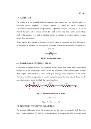
  • 1. 1 Week 1 1.1 RESISTOR The resistor is a two terminal electrical component that opposes the flow of either direct or alternating current, employed to protect, operate, or control the circuit. A resistor is a passive two-terminal electrical component that implements electrical resistance as a circuit element. Resistors act to reduce current flow, and, at the same time, act to lower voltage levels within circuits, it is used in electrical circuits to maintain a constant relation between current flow and voltage. When current flows through a resistance, electrical energy is converted into heat .The power P dissipated by a resistor (or the equivalent resistance of a resistor network) is calculated as: 𝑃 = đ‘‰đŒ Fig.1.1 Symbol of resistor (A) RESISTORS CONNECTED IN SERIES Components connected in series are connected along a single path, so the same current flows through all of the components. Series circuits are sometimes called current-coupled or daisy chain-coupled. The current in a series circuit goes through every component in the circuit. Therefore, all of the components in a series connection carry the same current. There is only one path in a series circuit in which the current can flow. Fig.1.2 Resistors connected in series I1 = I2= I3 = In 𝑅 𝑒𝑞. = 𝑅1 + 𝑅2 +...........+ 𝑅 𝑛 (B) RESISTORS CONNECTED IN PARALLEL The potential differences across the components are the same in magnitude, and they also have identical polarities. To find the total resistance of all components, add the reciprocals of
  • 2. 2 the resistances of each component and take the reciprocal of the sum. Total resistance will always be less than the value of the smallest resistance: Fig.1.3 Resistor connected on parallel 𝑅 𝑒𝑞.= 1 𝑅1 + 1 𝑅2 +........+ 1 𝑅𝑛 1.2 INDUCTOR An inductor or a reactor is a passive electrical component that can store energy in a magnetic field created by the electric current passing through it. An inductor's ability to store magnetic energy is measured by its inductance, in units of henries. Typically an inductor is a conducting wire shaped as a coil; the loops help to create a strong magnetic field inside the coil due to Ampere's Law. Due to the time-varying magnetic field inside the coil, a voltage is induced, according to Faraday's law of electromagnetic induction, which by Lenz's Law opposes the change in current that created it. Inductors are one of the basic components used in electronics where current and voltage change with time, due to the ability of inductors to delay and reshape alternating currents. Inductors called chokes are used as parts of filters in power supplies or to block AC signals from passing through a circuit. Fig.1.4 Symbol of inductor (A) APPLICATION OF INDUCTOR 1. Inductors are used extensively in analogy circuits and signal processing. Inductors in conjunction with capacitors and other components form tuned circuits which can emphasize or filter out specific signal frequencies.
  • 3. 3 2. An inductor is used as the energy storage device in some switched-mode power supplies. 3. Inductors are also employed in electrical transmission systems, where they are used to depress voltages from lightning strikes and to limit switching currents and fault current. 4. Larger value inductors may be simulated by use of gyrator circuit. 1.3 CAPACITOR A capacitor (formerly known as condenser) is a passive electronic component consisting of a pair of conductors separated by a dielectric (insulator). When there is a potential difference (voltage) across the conductors, a static electric field develops in the dielectric that stores energy and produces a mechanical force between the conductors. An ideal capacitor is characterized by a single constant value, capacitance, measured in farads. This is the ratio of the electric charge on each conductor to the potential difference between them. It may be polar or non polar type capacitor. In non polar terminal Fig. 1.5 Symbol of capacitor (A) APPLICATION 1. Capacitive touch switches are now used on many consumer electronic products. 2. To start the motor, a secondary winding is used in series with a non-polarized starting capacitor to introduce a lag in the sinusoidal current through the starting winding. 3. For improving power factor. 1.4 BASIC ELECTRICALDEFINITION (A) VOLTAGE Voltage is the electric energy charge difference of electric potential energy transported between two points. Voltage is equal to the work done per unit of charge against a static electric field to move the charge between two points. A voltage may represent either a source of energy (electromotive force), or lost, used, or stored energy (potential drop).
  • 4. 4 A voltmeter can be used to measure the voltage (or potential difference) between two points in a system. (B) CURRENT An electric current is a flow of electric charge. In electric circuits this charge is often carried by moving electrons in a wire. It can also be carried by ions in an electrolyte, or by both ions and electrons such as in a plasma. The SI unit for measuring an electric current is the ampere, which is the flow of electric charge across a surface at the rate of one coulomb per second. Electric current is measured using a device called an ammeter. (C) MAGNETIC INDUCTION A generator is a machine that converts mechanical energy into electrical energy by using the principle of magnetic induction. Magnetic induction is used to produce a voltage by rotating coils of wire through a stationary magnetic field, or by rotating a magnetic field through stationary coils of wire. This is one of the most useful and widely employed applications of producing vast quantities of electric power. (D) FLUX Magnetic flux (often denoted Ί or ΊB) through a surface is the surface integral of the normal component of the magnetic field B passing through that surface. The SI unit of magnetic flux is the Weber (wb), and the CGS unit is the max well. Magnetic flux is usually measured with a flux meter, which contains measuring coils and electronics that evaluates the change of voltage in the measuring coils to calculate the magnetic flux. 1.5 ELECTRICITY Electricity gives a wide variety of well-known effects, such as lightning, static electricity, electromagnetic induction and current. Electricity is set of physical phenomena associated with the presence and flow of electric charger addition, electricity permits the creation and reception of electromagnetic radiation such as radio waves. Electricity is the flow of electrons through a conductor. The amount of current (amps) is related to the voltage (volts) pushing the electrons and the degree of resistance to flow (ohms). During their flow around a circuit, electrons can be used to create a number of useful by products such as heat and light. As electrons flow, they alter the charge of the matter they flow through, which may also generate electromagnetic effects.
  • 5. 5 (A) PROPERTY OF ELECTRICITY 1. Heating effect 2. Magnetic effect 3. Chemical effect (B) APPLICATION OF ELECTRICITY 1. Electricity is a very convenient way to transfer energy, and it has been adapted to a huge, and growing, number of uses. 2. Electricity is also used to fuel public transportation, including electric buses and trains. 3. Electricity is used within telecommunications 4. The effects of electromagnetism are most visibly employed in the electric motor, which provides a clean and efficient means of motive power.
  • 6. 6 Week 2 2.1 INTERNATIONALSTANDERED TERMINALMARKING In any type of electrical machine, terminal marking is important during operating time. Terminal marking located on terminal box of machine. In every country, different terminal marking is used. For example, in India phase marking is R, Y, and B. In German country phase marking is R, S, and T. Similarly, for electric motor and alternator different terminal marking is used. (A) STANDARD TERMINAL MARKING FOR PHASE COUNTRY PHASE INDIA RED,YELLOW,BLUE UK RED,YELLOW,BLUE GERMAN R,S,T AMERICAN L1,L2,L3 Table 2.1 Standard terminal marking for phase (B) INTERNATIONAL STANDARD TERMINAL MARKING FOR ELECTRIC MOTOR COUNTRY TERMINAL MARKING INDIA A1,A2 B1,B2 C1,C2 UK A,A1 B,B1 C,C1 GERMAN U,V,W X,Y,Z AMERICAN T1,T2,T3 T4,T5,T6 Table 2.2 Standard terminal marking for electric motor
  • 7. 7 (C) INTERNATIONAL STANDARD TERMINAL MARKING FOR ALTERNATOR COUNTRY TERMINAL MARKING INDIA A1,A2 B1,B2 C1,C2 UK A,A1 B,B1 C,C1 GERMAN U,V,W X,Y,Z AMERICAN T1,T2,T3 T4,T5,T6 Table 2.3 Standard terminal marking for alternator 2.2 CELL An electrochemical cell is a device capable of either generating electrical energy from chemical reactions or facilitating chemical reactions through the introduction of electrical energy. A common example of an electrochemical cell is a standard 1.5-volt battery meant for consumer use. Some electrical cells, once their potential (chemical) energy has all been changed to electricity and used up, must be thrown away. They are no good anymore. These are called primary cells. Primary cells include the ones you usually put in a flashlight, in a transistor radio, and in various other consumer devices. Fig. 2.1 Symbol of cell (A) OPERATION OF BATTERY When the circuit is completed, a deflection is observed in the (G) towards the zinc electrode indicating that the e- is flowing from the Zn electrode to Cu electrode. At the Zn electrode, oxidation takes place.
  • 8. 8 Zn → Zn+2 + 2e- (oxidation) (1) The electron 'e' is removed, lost or retained by the metal move through the material contained in the electrode, and reach the Copper electrode at which they are accepted by Copper ions of the solution to form the neutral Copper atoms. Cu+2 + 2e- → Cu (2) In an electrochemical cell, each electrode constitutes one half of the cell and the reaction taking place at the electrode is called half-cell reaction. The overall cell reaction is obtained by adding the two half-cell reactions (1) and (2). Zn + Cu+2 → Zn+2 + Cu (Overall Reaction) From this, it is found that, when Zn is added to CuSO4 solution, Zn displaces Cu from CuSO4 with the liberation of heat. But, in the electrochemical cell, there is no direct contact between Zn and CuSO4. The heat energy that would have been liberated appears in the form of electrical energy. Hence, the electrochemical cell acts as a source of current, although for a short interval. (B) APPLICATION OF CELL 1. Wrist and wall watch 2. Electronics items 3. Light sources like torch (C) IDENTIFICATION OF BATTERY TERMINAL 1. Red one goes to the positive terminal and the black goes to negative 2. Marking of negative (-) and positive (+) terminal. 3. Usually the positive post is slightly larger than the negative. When battery terminal pass in a potato via wire, then if Potato colour red Positive terminal Potato colour blue Negative terminal Table 2.4 Identification of battery terminal
  • 9. 9 2.3 BATTERY An electric battery is a device consisting of two or more electrochemical cell that converts stored chemical energy into electrical energy. Each cell contains a positive terminal, or cathode, and a negative terminal, or anode .Cell allows ions to move between the electrodes and terminals, which allows current to flow out of the battery to perform work. . Fig. 2.2 Symbol of cell (A) OPERATION OF BATTERY Batteries convert chemical energy directly to electrical energy. A battery consists of some number of voltaic cells. Each cell consists of two half-cells connected in series by a conductive electrolyte containing anions and cations. One half-cell includes electrolyte and the negative electrode, the electrode to which anions (negatively charged ions) migrate; the other half-cell includes electrolyte and the positive electrode to which cat ions (positively charged ions) migrate. Redox reactions power the battery. Cat ions are reduced (electrons are added) at the cathode during charging, while anions are oxidized (electrons are removed) at the anode during discharge. The electrodes do not touch each other, but are electrically connected by the electrolyte. Some cells use different electrolytes for each half-cell. A separator allows ions to flow between half-cells, but prevents mixing of the electrolytes. (B) APPLICATION 1. Ship, Plain 2. Inverter 3. Railway 4. Power system 5. Domestic purpose
  • 10. 10 2.4 GENERATOR A machine is a tool containing one or more parts that uses energy to perform an intended action. Machines are usually powered by mechanical, chemical, thermal, or electrical means, and are often motorized. An electrical machine is the apparatus that converts energy in three categories: 1. Generators which convert mechanical energy to electrical energy 2. Motors which convert electrical energy to mechanical 3. Transformers which change the voltage level of an alternating current Fig. 2.3 Generator An electrical machine which capable to convert mechanical energy into electrical energy. A generator forces electrons to flow through an external electrical circuit. It is somewhat analogous to a water pump, which creates a flow of water but does not create the water inside. The source of mechanical energy, the prime mover, may be a reciprocating or turbine steam engine, water falling through a turbine or waterwheel, an internal combustion engine, a wind turbine, a hand crank, compressed air or any other source of mechanical . (A) TYPE OF GENERATOR 1. AC generator 2. DC generator Further of these, AC generator and DC generator has also many types. AC generator may be synchronous or asynchronous generator.
  • 11. 11 Fig. 2.4 Classification of generator 1. AC generator An AC generator converts mechanical energy into alternating current electricity. Because power transferred into the field circuit is much less than power transferred into the armature circuit, AC generators nearly always have the field winding on the rotor and the armature winding on the stator. 2. DC generator A DC generator produces direct current electrical energy from mechanical energy. A DC generator can operate at any speed within mechanical limits and always output a direct current waveform. Direct current generators known as dynamos work on exactly the same principles as alternators, but have a commutate on the rotating shaft, which convert the alternating current produced by the armature to direct current. (B) APPLICATION 1. Electrolytic process 2. Welding process 3. For supplying excitation 4. To compensate the voltage drop in Feeders. 5. Used as booster 6. Battery charging
  • 12. 12 2.5 MOTOR An electric motor converts electrical energy into mechanical energy. The reverse process of electrical generators, most electric motors operate through interacting magnetic fields and current-carrying conductors to generate rotational force. Electric motors are found in applications as diverse as industrial fans, blowers and pumps, machine tools, household appliances, power tools, and disk drives. (A) TYPES OF MOTOR 1. AC motors 2. DC motor Fig 2.5 Classification of electric motor 1. AC motor An AC motor converts alternating current into mechanical energy. It commonly consists of two basic parts, an outside stationary stator having coils supplied with alternating current to produce a rotating magnetic field, and an inside rotor attached to the output shaft that is given a torque by the rotating field. The two main types of AC motors are distinguished by the type of rotor used. 2. DC motor The brushed DC electric motor generates torque directly from DC power supplied to the motor by using internal commutation, stationary permanent magnets, and rotating electrical
  • 13. 13 magnets. Brushes and springs carry the electric current from the commutate to the spinning wire windings of the rotor inside the motor. Brushless DC motors use a rotating permanent magnet in the rotor, and stationary electrical magnets on the motor housing. A motor controller converts DC to AC. This design is simpler than that of brushed motors because it eliminates the complication of transferring power from outside the motor to the spinning rotor. An example of a brushless, synchronous DC motor is a stepper motor which can divide a full rotation into a large number of steps. The motor's position can be controlled precisely without any feedback mechanism as long as the motor is carefully sized to the application. (B) TYPES OF AC MOTOR 1. Permanently star connected motor 2. Permanently delta connected motor 3. Permanently star and delta connected motor 1. Permanently star connected motor In this motor terminals are connected in star connection only permanently. These motor have power rating from 0.25 HP to 5 HP Fig. 2.7 Star connected motor . These motor are available in several pole. As no. of poles increases speed will decreases. POLE SPEED (rpm) 2 2900 4 1440 6 950 8 725 Table 2.5 Speed v/s pole relation of permanent star connected motor
  • 14. 14 Permanently delta connected motor These motor are terminals connected in delta connection. These are also available in 2-5 HP. Fig 2.8 Delta connected motor As no of poles increases, speed will decreases of motor. POLE SPEED (rpm) 2 2900 4 1440 6 950 8 725 Table 2.6 Speed v/s pole relation of permanent delta connected motor Permanently star and delta connected motor Fig.2.9 Star and delta connected motor
  • 15. 15 These are motor terminal connected in star as well as delta connection. In it 6 terminals are available. These motor are available up to 2000 HP power. Power rating of squirrel cage induction motor 5-7.5-10-15-20-30 HP 300HP-500HP 30-40-50 HP 500HP-1000HP 50-75-100 HP 1000HP-3000HP 100HP-200HP 1000HP-1500HP 200HP-300HP 300HP-500HP POLE SPEED(rpm) 2 2900 4 1440 6 950 8 725 Table 2.7 Speed v/s pole relation of star and delta motor 2.6 OHM’S LAW Ohm's law states that the current through a conductor between two points is directly proportional to the potential difference across the two points. Where I is the current through the conductor in units of amperes, V is the potential difference measured across the conductor in units of volts, and R is the resistance of the conductor in units of ohms. More specifically, Ohm's law states that the R in this relation is đŒ = 𝑉 𝑅 The interdependence between current, voltage, and resistance is one of the most fundamental rules, or laws, in electrical circuits. It is called Ohm’s Law, named after the scientist who supposedly first expressed it.
  • 16. 16 Fig. 2.10 Ohm’s law Three formulas denote this law 𝑉 = đŒđ‘… 2.7 STAR AND DELTA CONNECTION There are two types of system available in electric circuit, single phase and three phase system. In single phase circuit, there will be only one phase. The current will flow through only one wire and there will be one return path called neutral line to complete the circuit. So in single phase minimum amount of power can be transported. Three phase circuit is the poly phase system where three phases are sending together from the generator to the load. Each phase are having a phase difference of 120°, ie. 120° angle electrically. So from the total of 360°, three phases are equally divided into 120° each. The power in three phase system is continuous as all the three phases are involved in generating the total power. (A) STAR CONNECTION Fig. 2.11 Star connection In star connection, there is four wire, three wires are phase wire and fourth is neutral which is taken from the star point. Star connection is preferred for long distance power transmission because it is having the neutral point. In this we need to come to the concept of balanced and unbalanced current in power system.
  • 17. 17 When equal current will flow through all the three phases, then it is called as balanced current. And when the current will not be equal in any of the phase, then it is unbalanced current. In this case, during balanced condition there will be no current flowing through the neutral line and hence there is no use of the neutral terminal. But when there will be unbalanced current flowing in the three phase circuit, neutral is having a vital role. It will take the unbalanced current through to the ground and protect the transformer. Unbalanced current affects transformer and it may also cause damage to the transformer and for this star connection is preferred for long distance transmission. Line voltage = √3 phase voltage Line current = phase current (B) DELTA CONNECTION Fig. 2.12 Delta connection In delta connection, there is three wires alone and no neutral terminal is taken. Normally delta connection is preferred for short distance due to the problem of unbalanced current in the circuit. The figure is shown below for delta connection. In the load station, ground can be used as neutral path if required. In delta connection, the line voltage is same with that of phase voltage. And the line current is √3 times of phase current. It is shown as expression below: Line voltage = phase voltage Line current = √3 phase current (C) TYPES OF DELTA CONNECTION 1. Forward delta
  • 18. 18 2. Reverse delta 1. Forward delta Fig. 2.13 Forward delta connection In this type of delta A1 connected to B2, B1 connected to C2 and C1 connected to A2. In 1966, ISO declares forward delta as standard delta. 2. Reverse delta Fig. 2.14 Reverse delta connection
  • 19. 19 Week 3 3.1 CLASS OF INSULATION The type of insulation is used in a motor depends upon the operating temperature that the motor will experience. Average insulation life decreases rapidly with increase in motor internal operating temperature. (A) TYPES OF INSULATION Table 3.1 Insulation of motor 3.2 DEGREE OF PROTECTION 1. The degree of protection is classified in IS 4691. 2. It is denoted by two digits. 3. The first digit denotes protection against solid bodies. 4. The second digit denotes protection against liquid. 5. It is represented by IP. 6. It provides knowledge about sensitivity of motor. CLASS OF INSULATION TEMPERATURE (in Degree centigrade) Y 70-90 A 90-105 B 120 E 130 F 155 H 180-200 C 200-240
  • 20. 20 DEGREE OF PROTECTION Parameter No Protection Water falling vertical Water falling to 150 from vertical Water falling up to 600 vertical Water splashes Water projected by nozzle Water from heavy seas 0 1 2 3 4 5 6 0 No protection 1 Special protection against 50mm diameter 2 DP protection against 12 mm diameter IP 21 IP 22 IP23 4 TEFC protection against 1 mm diameter IP 44 5 TEFC protection against powder IP 54 IP 55 IP56 Table 3.2 Degree of protection
  • 21. 21 3.3 NAME PLATE AND ITS IMPORTANT TERMS AND LEGEND NAME OF MANUFATURER NEW MAN ELECTRIC MOTOR LIMITED (ENGLAND) FRAME SIZE 200-L MODEL DR-9002 STANDARD BS KW/HP 75/100 PHASE 3 PHASE HZ 50 HZ S.NO C-4865 RPM 2900 AMB 40 DEGREE CONNECTION STAR, DELTA, STAR-DELTA TERMINAL STANDARD MARKING JIS D.E. BEARING 6210-C3 N.D.E. BEARING 6210-C3 IP 44 POWER FACTOR 0.8 TYPE SQUIRREL CAGE T.E.F.C CLASS OF INSULATION B VOLT 415+-2% 400-415,380,400,440 TAP CHANGING NAME OF THE STANDARD BS,IS,NEMA,CSA Table 3.3 Name plate of motor
  • 22. 22 3.4 SINGLE PHASE MOTOR Single-phase motors do not have the rotating magnetic field of a three phase motor and require a secondary magnetic field that causes the rotor to move in the proper direction. (A) SINGLE PHASE TWO POLE 1. Symbolic diagram Fig. 3.1 Symbolic diagram 2. Location diagram Fig. 3.2 Location diagram
  • 23. 23 3. Schematic diagram Fig. 3.3 Schematic diagram (B) SINGLE PHASE FOUR POLE In this type of four pole motor, four running winding and four starting winding are connected. From view of symbolic diagram, four pole and two pole motor are same. 1. Symbolic diagram Fig. 3.4 Symbolic diagram
  • 24. 24 2. Location diagram Fig. 3.5 location diagram 3. Schematic diagram Fig. 3.6 Schematic diagram 3.5 TWO PHASES WITH THREE VARIABLE SPEEDSMOTOR In this type of motor, there are different tapping for different speed. As our requirement, we can connect one phase to different tapping terminals. There is a selector switch, which is used to connect the tapping. A capacitor is connected in series with starting winding to start the motor.
  • 25. 25 (A) BENIFITS OF MOTOR 1. Soft starting of the motor & load reducing mechanical stresses & reduced water hammer with pumps. 2. Energy Savings 3. Ability to control the speed of the motor. (B) DIFFERENT REPRESENTATION 1. Symbolic diagram Fig. 3.7 Symbolic diagram 2. Schematic diagram Fig. 3.8 Schematic diagram
  • 26. 26 3.6 TRANSFORMER A transformer is a static device that converts alternating current from one voltage level to another level (higher or lower), or to the same level, without changing the frequency. A transformer transfers electrical energy from one circuit to another through inductively coupled conductors the transformer's coils. A varying electric current in the first or primary winding creates a varying magnetic flux in the transformer's core and thus a varying magnetic field through the secondary winding. Fig. 3.9 Symbol of transformer Two parallel lines represent magnetic coupling. (A) OPERATION OF TRANSFORMER Fig. 3.10 Operation of transformer A varying current in the transformer's primary winding creates a varying magnetic flux in the core and a varying magnetic field impinging on the secondary winding. This varying magnetic field at the secondary induces a varying electromotive force (EMF) or voltage in the secondary winding. The primary and secondary windings are wrapped around a core of infinitely high magnetic permeability so that all of the magnetic flux passes through both the primary and secondary windings. With a voltage source connected to the primary winding
  • 27. 27 and load impedance connected to the secondary winding, the transformer currents flow in the indicated directions. According to Faraday's law of induction, since the same magnetic flux passes through both the primary and secondary windings in an ideal transformer, a voltage is induced in each winding in the secondary winding case, in the primary winding case. The primary EMF is sometimes termed counter EMF. This is in accordance with Lenz's law, which states that induction of EMF always opposes development of any such change in magnetic field. (B) TYPES OF TRANSFORMER 1. Single phase transformer 2. Three phase’s transformer (C) CONSTRUCTION PART OF TRANSFORMER 11.4.1 Cores 11.4.2 Windings 11.4.3 Cooling 11.4.4 Insulation drying 11.4.5 Bushings (D) APPLICATION OF TRANSFORMER 1. Isolate two circuits. 2. Change the voltage level. 3. A measuring of voltage and current of transmission line. 3.7 AUTO TRANSFORMER An autotransformer is an electrical transformer with only one winding. In an autotransformer, portions of the same winding act as both the primary and secondary sides of the transformer. In contrast, an ordinary transformer has separate primary and secondary windings which are not connected.
  • 28. 28 Fig. 3.11 Arrangement of auto transformer (A) OPERATION An autotransformer has a single winding with two end terminals, and one or more terminals at intermediate tap points, or it is a transformer in which the primary and secondary coils have part or all of their turns in common. The primary voltage is applied across two of the terminals, and the secondary voltage taken from two terminals, almost always having one terminal in common with the primary voltage. The primary and secondary circuits therefore have a number of windings turns in common. Since the volts-per-turn is the same in both windings, each develops a voltage in proportion to its number of turns. In an autotransformer part of the current flows directly from the input to the output, and only part is transferred inductively, allowing a smaller, lighter, cheaper core to be used as well as requiring only a single winding. However the voltage and current ratio of autotransformers can be formulated the same as other two-winding transformers: 𝑉1 𝑉2 = 𝑁1 𝑁2 = đŒ2 đŒ1 (B) APPLICATION 1. Power transmission and distribution 2. Railways 3. Audio system (C) ADVANTAGES OF AUTO TRANSFORMER 1. Its efficiency is more when compared with the conventional one. 2. Its size is relatively very smaller. 3. Voltage regulation of autotransformer is much better.
  • 29. 29 4. Lower cost 5. Low requirements of excitation current. 6. Less copper is used in its design and construction
  • 30. 30 Week 4 4.1 DEPARTMENT OF POWER SYSTEM An electric power system is a network of electrical components used to supply, transmit and use electric power. An example of an electric power system is the network that supplies a region's homes and industry with power for sizable regions, this power system is known as the grid and can be broadly divided into the generators that supply the power, the transmission system that carries the power from the generating centres to the load centres and the distribution system that feeds the power to nearby homes and industries. Smaller power systems are also found in industry, hospitals, commercial buildings and homes. The majority of these systems rely upon three-phase AC power the standard for large-scale power transmission and distribution across the modern world. Fig 4.1 Power system structure (A) DEPARTMENT OF POWER SYSTEM 1. Generation 2. Transmission 3. Distribution 1. Generation Electricity generation is the process of generating electric power from other sources of primary energy.. His basic method is still used today: electricity is generated by the movement of a loop of wire, or disc of copper between the poles of a magnet. For electric utilities, it is the first process in the delivery of electricity to consumers.
  • 31. 31 Electricity is most often generated at a power station by electromechanical generators, primarily driven by heat engines fuel by chemical combustion or nuclear fission but also by other means such as the kinetic energy of flowing water and wind. Other energy sources include solar photo voltaic and geothermal power. Fig. 4.2 Different sources of generate power supply 2. Transmission Electric-power transmission is the bulk transfer of electrical energy, from generating power plants to electrical substations located near demand centre. This is distinct from the local wiring between high-voltage substations and customers, which is typically referred to as electric power distribution. Most transmission lines are high-voltage three-phase alternating current (AC), although single phase AC is sometimes used in railway electrification systems. High-voltage direct-current (HVDC) technology is used for greater efficiency at very long distances (typically hundreds of miles (kilo meters), or in submarine power cables (typically longer than 30 miles (50 km)). HVDC links are also used to stabilize and control problems in large power distribution networks where sudden new loads or blackouts in one part of a network can otherwise result in synchronization problems and cascading failures. Electricity is transmitted at high voltages (120 kV or above) to reduce the energy losses in long-distance transmission. Power is usually transmitted through overhead power lines. Underground power transmission has a significantly higher cost and greater operational limitations but is sometimes used in urban areas or sensitive locations.
  • 32. 32 3. Distribution An electric power distribution system is the final stage in the delivery of electric power; it carries electricity from the transmission system to individual consumers. Distribution substations connect to the transmission system and lower the transmission voltage to medium voltage ranging between 2 kV and 35 kV with the use of transformers. Primary distribution lines carry this medium voltage power to distribution transformers located near the customer's premises. Distribution transformers again lower the voltage to the utilization voltage of household appliances and typically feed several customers through secondary distribution lines at this voltage. Commercial and residential customers are connected to the secondary distribution lines through service drops. Customers demanding a much larger amount of power may be connected directly to the primary distribution level or the sub transmission level. 4.2 LOW VOLTAGE CONTROLPANEL There are held two types of circuit, control circuit and power circuit. In control circuit, control components of panel like start, stop push button, auxiliary contact, tripping contacts and no volt coil are present. (A) CONTROL PANEL DIAGRAM Fig. 4.4 low voltage control panel
  • 33. 33 (B) DIFFERENT COMPONENTS OF CONTROL PANEL 1. Air break contactors A contactor is an electrically controlled switch used for switching an electrical power circuit, similar to a relay except with higher current ratings. A contactor is controlled by a circuit which has a much lower power level than the switched circuit. Characteristic of contactor 1. Rated current up to 10,000 A. 2. Trip characteristics often fully adjustable including configurable trip thresholds and delays. 3. Usually electronically controlled—some models are microprocessor controlled. 2. No volt coil Mostly no volt coil energise through two phases. But in preset scenario single phase no volt coil is also available, that operating voltage is 230v. No volt coil is connected through auxiliary contact and air circuit breakers. 3. Stop button Red button indicates red push button. It is used to cut off the supply from machine. If in any panel more than one stop wants to connect then all stop button must be in series. Stop button become normally close. Fig. 4.5 Stop button 4. Start button Green button indicates start push button. It is used to ON the power supply in control circuit. More than one start button must be in parallel manner. Start button become normally open. Fig. 4.6 Start button
  • 34. 34 5. Auxiliary contact Auxiliary contact is connected in parallel to start button. 6. Tripping contact In overloading condition of machine, it become trip and power supply off. Tripping contact is connected to stop button in series. (C) Application 1. Starting of motor 2. Interlocking of motors 3. Automation of motor 4.3 METHOD OF STARTING OF THREE-PHASE INDUCTION MOTOR The need for using starters in IM to reduce the starting current, first two (Star-Delta and Auto-transformer) types of starters used for Squirrel cage IM and then, the starter using additional resistance in rotor circuit, for Wound rotor (Slip-ring) IM, are presented along with the starting current drawn from the input (supply) voltage, and also the starting torque developed using the above starters. (A) NEED OF DIFFERENT STARTING METHODS In starting of motor, starting current is very large. From these, winding may be damage. For protection from large starting current, we can use different methods of starting. With the help of these starting methods, we can limit starting voltage and starting current. (B) TYPES OF STARTING METHODS 1. Star delta starter This type is used for the induction motor, the stator winding of which is nominally delta- connected. This is a simple starter, which can be easily reconfigured. The motor must be delta connected during a normal run, in order to be able to use this starting method. The received starting current is about 30 % of the starting current during direct on line start and the starting torque is reduced to about 25 % of the torque available at a D.O.L start. This starting method only works when the application is light loaded during the start. If the motor is too heavily
  • 35. 35 loaded, there will not be enough torque to accelerate the motor up to speed before switching over to the delta position. When starting up, the load torque is low at the beginning of the start and increases with the square of the speed. When reaching approximately 80-85% of the motor rated speed the load torque is equal to the motor torque and the acceleration ceases. To reach the rated speed, a switch over to delta position is necessary, and this will very often result in high transmission and current peaks. In some cases the current peak can reach a value that is even bigger than for a D.O.L start. Applications with a load torque higher than 50% of the motor rated torque will not be able to start using the star-delta starter. When starting up, the load torque is low at the beginning of the start and increases with the square of the speed. When reaching the motor rated speed the load torque is equal to the motor torque and the acceleration ceases. To reach the rated speed, a switch over to delta position is necessary, and this will very often result in high transmission and current peaks. It may be manual star delta starter or automatic star delta starter. In automatic star delta starter timer is used. Fig. 4.7 Manual star delta starter 2. Direct on-line starter Induction motors can be started Direct-on-Line (DOL), which means that the rated voltage is supplied to the stator, with the rotor terminals short-circuited in a wound rotor (slip-ring)
  • 36. 36 motor. For the cage rotor, the rotor bars are short circuited via two end rings. The main problem in starting induction motors having large or medium size lies mainly in the requirement of high starting current, when started direct-on-line (DOL). Assume that the distribution line is starting from a substation, where the supply voltage is constant. The line feeds a no. of consumers, of which one consumer has an induction motor with a DOL starter, drawing a high current from the line, which is higher than the current for which this line is designed. This will cause a drop in the voltage, all along the line, both for the consumers between the substation and this consumer, and those, who are in the line after this consumer. This drop in the voltage is more than the drop permitted, i.e. higher than the limit as per ISS, because the current drawn is more than the current for which the line is designed. Only for the current lower the current for which the line is designed, the drop in voltage is lower the limit. So, the supply authorities set a limit on the rating or size of IM, which can be started DOL. Any motor exceeding the specified rating, is not permitted to be started DOL, for which a starter is to be used to reduce the current drawn at starting. Fig. 4.8 DOL starter 3. Auto transformer starter This is another starting method that reduces the starting current and starting torque but contrary to Star-Delta starting where this starting method needs three wires and three terminals on the motor. Autotransformers are generally equipped with taps at each phase in
  • 37. 37 order to adapt the starting parameters to the application starting requirement. During starting, the motor is connected to the autotransformer taps. With the star and autotransformer contactors closed, the motor is under reduced voltage. Consequently the torque is reduced as the square of the applied voltage. When the motor reaches the 80 to 95% of the nominal speed, the star contactor opens. Fig. 4.9 Auto transformer 4. Resistance starter In a slip-ring (wound rotor) induction motor, resistance can be inserted in the rotor circuit via slip rings, so as to increase the starting torque. The input (stator) current is proportional to the rotor current. The starting current (input) reduces, as resistance is inserted in the rotor circuit. But the starting torque, [Tst=3.(Ist)2.(r2+Rext)] increases, as the total resistance in the rotor
  • 38. 38 circuit is increased. Though the starting current decreases, the total resistance increases, thus resulting in increase of starting torque and also obtained by using the expression given earlier, for increasing values of the resistance in the rotor circuit. If the additional resistance is used only for starting, being rated for intermittent duty, the resistance is to be decreased in steps, as the motor speed increases. Fig. 4.10 Resistance starter
  • 39. 39 Week 5 5.1 FORWARD AND REVERSE OPERATIONOF INDUCTION MOTOR To change the direction a three phase induction machine rotation, two of its phases needs to be exchanged, thus changing the phase sequence form, say RYB to RBY. This can be accomplished by using two contactors, one for the forward or CW rotation and one for the reverse or CCW rotation. The forward and reverse contactors are mechanically interlocked i.e., if one of them is closed the other cannot close. This is done to avoid dead short circuit in case both the contactors closing simultaneously. Also electrical interlocking could be provided using the contactors control contacts. (A) CIRCUIT DIAGRAM Fig. 5.1 Forward and reverse operation of motor
  • 40. 40 (B) CIRCUIT DESCRIPTION In this circuit, there are control circuit and power circuit as usual. In control circuit, forward and reverse no volt coil is present. 5.2 LADDER PROGRAMMING A hardwired control circuit can be represented by conventional hardwired relay ladder diagram. In any hardwired circuit, there should be electrical continuity in order for the load to energize. Electrical sequence of operation in hardwired relay circuits can be represented by electrical ladder diagram. Ladder diagram shows the interconnection of field devices. In the ladder diagram, each rung shows how a field device is turned on and also shows how it interacts with next field devices. Ladder diagrams are specialized schematics commonly used to document industrial control logic systems. They are called “ladder” diagrams because they resemble a ladder, with two vertical rails (supply power) and as many “rungs” (horizontal lines) as there are control circuits to represent. (A) LOGICAL OPERATION Logical operations performed by PLC are nothing but fundamental logic operation, using fundamental logic operators like: AND, OR, and NOT. These operators are used to combine the instructions on a PLC rung so as to make the outcome of each rung either true or false. 1. AND logic operation Fig. 5.2 AND logic The series circuit of 2 switches can be looked as an AND logic function. In fig. both switch1 and switch2, must be closed to have electrical continuity. When there is electrical continuity, output (light1) will energize. Hence the keyword here is AND. 2. OR logic operation In an OR - LOGIC function, the output is true if any input is true. The OR logic also states that if all inputs are true, the output will be true.
  • 41. 41 Fig. 5.3 OR logic In the above figure, if switch1 OR switch2 is energized then light1 will energize. Also, if both SW1 and SW2 are true, the output will also be true. 3. NOT logic operation A normally closed relay contact passes power any time when the relay coil is not energized. In the same manner, the normally closed PLC ladder logic instruction will pass power any time when the input status file bit associated is not a 1. In this condition, the physical hardware input is not sending an input signal into the PLC's input module. The opposite of normally open PLC instruction or contact is the NOT logic. NOT logic can be used in conjunction with AND or OR logic, when a logical 0 in the status file is expected to activate some output device. In other words, NOT logic is used when an input is not energized i.e., 0 in the associated status bit, the output should be energized. Also, when the input is energized i.e., 1 in the associated status bit, the output should not be energized. Fig. 5.4 NOT logic (C) ADVANTAGE OF LADDER PROGRAMMING 1. They are also easy to troubleshoot. 2. Allowing for less mechanical downtime. 5.3 TIMER A timer is specialized type of clock for measuring time intervals. A timer which counts upwards from zero for measuring elapsed time is often called a stopwatch; a device which counts down from a specified time interval is more usually called a timer or a countdown
  • 42. 42 timer. A simple example for this type is an hourglass. Time switches, timing mechanisms which activate a switch, are sometimes also called "timers". (A) TYPES OF TIMER Different types of timer are available 1. Mechanical timer Mechanical timers use clockwork to measure time. Manual timers are typically set by turning a dial to the time interval desired; turning the dial stores energy in a mainspring to run the mechanism. They function similarly to a mechanical alarm clock; the energy in the mainspring causes a balance wheel to rotate back and forth. 2. Electromechanical timer Short-period bimetallic electromechanical timers use a thermal mechanism, with a metal finger made of strips of two metals with different rates of thermal expansion sandwiched together; steel and bronze are common. An electric current flowing through this finger causes heating of the metals, one side expands less than the other, and an electrical contact on the end of the finger moves away from or towards an electrical switch contact 3. Electronic timer Electronic timers are essentially quartz clocks with special electronics, and can achieve higher precision than mechanical timers. Electronic timers have digital electronics, but may have an analog or digital display. Integrated circuits have made digital logic so inexpensive that an electronic timer is now less expensive than many mechanical and electromechanical timers. Individual timers are implemented as a simple single-chip computer system, similar to a watch and usually using the same, mass-produced, technology. (B) APPLICATION OF TIMER 1. Auto star delta starter of motor 2. Toaster, washing machine 3. Clocks, stopwatch etc.
  • 43. 43 (C) AUTOMATIC STAR DELTA STARTER USING TIMER Fig. 5.5 Automatic star delta starter 1. Power circuit The main circuit breaker serves as the main power supply switch that supplies electricity to the power circuit. The main contactor connects the reference source voltage R, Y, B to the primary terminal of the motor U1, V1, W1.In operation, the Main Contactor and the Star Contactor are closed initially, and then after a period of time, the star contactor is opened, and then the delta contactor is closed. The control of the contactors is by the timer built into the starter. The Star and Delta are electrically interlocked and preferably mechanically interlocked as well. 2. Control circuit In control circuit, auxiliary contactor, start button, stop button, no volt coils are connected as usual. There is interlocking also possible. From L1 The phase current flows to thermal overload contact through Fuse, then OFF Push button, On Push button Interlocking Contact 2, and then C3. This way, the circuit is completed.
  • 44. 44 3. Advantages 1. Simple Design and Operation 2. Comparatively cheaper than other voltage controlling methods 3. Torque and Current performance of the Star delta starter is well. 4. It draws two times starting current of the FLA (Full Load Ampere) of the connected motor 5. It reduced the starting current to one-third (approximately) as compared to DOL 4. Disadvantage 1. Starting Torque is also reduce to one-third because starter reduce the starting current to one-third of the rated current [as Line voltage also reduced to 57% (1/√3)] 2. It required Six leads or terminals Motor (Delta Connected) 3. For Delta connection, the supply voltage must be same as the rated motor voltage. 4. At switching time (From Star to Delta), if the motor does not reach at least 90% of its rated speed, then the current peak may be equally high as in Direct ON Line starter( D.O.L), thus it may cause harmful effects on the contactors contacts, so it would not be reliable.
  • 45. 45 Week 6 6.1 EARTH LEAKAGE CIRCUIT BREAKER An Earth Leakage Circuit Breaker (ELCB) is a safety device used in electrical installations with high earth impedance to prevent shock. It detects small stray voltages on the metal enclosures of electrical equipment, and interrupts the circuit if a dangerous voltage is detected. Once widely used, more recent installations instead use residual current circuit breakers which instead detect leakage current directly. (A) OPERATION An ELCB is a specialised type of latching relay that has a building's incoming mains power connected through its switching contacts so that the ELCB disconnects the power in an earth leakage (unsafe) condition. The ELCB detects fault currents from live to the earth (ground) wire within the installation it protects. If sufficient voltage appears across the ELCB's sense coil, it will switch off the power, and remain off until manually reset. A voltage-sensing ELCB does not sense fault currents from live to any other earthed body. (B) PURPOSE The main purpose of earth leakage protectors is to prevent injury to humans and animals due to electric shock. (C) Types of ELCB 1. Voltage ELCB A single phase voltage-ELCB will have six terminals. These are line in, line out, neutral in, earth, fault, and neutral out. The working principle of voltage ELCB is quite simple. One terminal of the relay coil is connected to the metal body of the equipment to be protected against earth leakage and other terminal is connected to the earth directly. If any insulation failure occurs or live phase wire touches the metal body, of the equipment, there must be a voltage difference appears across the terminal of the coil connected to the equipment body and earth. This voltage difference produces a current to flow the relay coil.
  • 46. 46 2. Current ELCB The working principle of current earth leakage circuit breaker or RCCB is also very simple as voltage operated ELCB but the theory is entirely different and residual current circuit breaker is more sensitive than ELCB. Actually, ELCBs are of two kinds, but it is general practice to refer voltage based ELCB as simple ELCB. And current based ELCB is referred as RCD or RCCB. Here one CT core is energized from both phase wise and neutral wire. A residual-current circuit breaker (RCCB) is the commonly used ELCB. A RCCB consists of a 3 winding transformer, which has 2 primary windings and one secondary winding. Neutral and live wires act as the two primary windings. A wire wound coil is the secondary winding. The current through the secondary winding is zero at the balanced condition. 3. Single phase ELCB Fig. 6.1 Single phase ELCB
  • 47. 47 4. Three Phases ELCB Fig. 6.2 Three phase ELCB (D) ADVANTAGES 1. They are less sensitive to fault conditions. 2. ELCB has fewer nuisance trips. 3. ELCB can be arranged to protect against cable damage only, and not trip on faults in down line installations. 6.2 CIRCUIT BREAKER A circuit breaker is an automatically operated electrical switch designed to protect an electrical circuit from damage caused by overload or short circuit. Its basic function is to detect a fault condition and interrupt current flow. Unlike a fuse, which operates once and then must be replaced, a circuit breaker can be reset (either manually or automatically) to resume normal operation. Circuit breakers are made in varying sizes, from small devices that
  • 48. 48 protect an individual household appliance up to large switchgear designed to protect high voltage circuits feeding an entire city. (A) OPERATION A circuit breaker works in one of two ways, with an electromagnet (or solenoid) or a bi-metal strip. In either case, the basic design is the same: when turned on, the breaker allows electrical current to pass from a bottom to an upper terminal across the solenoid or strip. When the current reaches unsafe levels, the magnetic force of the solenoid becomes so strong that a metal lever within the switch mechanism is thrown, and the current is broken. Alternately, the metal strip bends, throwing the switch and breaking the connection. To reset the flow of electricity after the problem is resolved, the switch can simply be turned back on, reconnecting the circuit. Circuit breakers are often found in a cabinet of individual switches, called a breaker box. The simple switch action of a circuit breaker also makes it easy to turn off an individual circuit in a house if it's necessary to work on the wiring in that location. (B) TYPES OF CIRCUIT BREAKER Many different classifications of circuit breakers can be made, based on their features such as voltage class, construction type, interrupting type, and structural features. 1. Low-voltage circuit breakers 2. Magnetic circuit breaker 3. Thermal magnetic circuit breaker 4. Common trip circuit breaker 5. Sulphur hexafluoride (SF6) circuit breaker 6.3 FUSE In electronics and electrical engineering, a fuse is a type of low resistance resistor that acts as a sacrificial device to provide over current protection, of either the load or source circuit. Its essential component is a metal wire or strip that melts when too much current flows through it, interrupting the circuit that it connects. Short circuits, overloading, mismatched loads, or device failure are the prime reasons for excessive current. Fuses are an alternative to circuit breakers.
  • 49. 49 A fuse interrupts excessive current ("blows") so that further damage by overheating or fire is prevented. Wiring regulations often define a maximum fuse current rating for particular circuits. Over current protection devices are essential in electrical systems to limit threats to human life and property damage. The time and current operating characteristics of fuses are chosen to provide adequate protection without needless interruption. Slow blow fuses are designed to allow harmless short term currents over their rating while still interrupting a sustained overload. Fuses are manufactured in a wide range of current and voltage ratings to protect wiring systems and electrical equipment. Fig. 6.3 Symbol of fuse (A) CONSTRUCTION The fuse element is made of zinc, copper, silver, aluminium, or alloys to provide stable and predictable characteristics. The fuse ideally would carry its rated current indefinitely, and melt quickly on a small excess. The element must not be damaged by minor harmless surges of current, and must not oxidize or change its behaviour after possibly years of service. (B) OPERATION There are many different types of fuses for residential and commercial use, but the most common type is made up of a metal wire or filament that is enclosed in a glass or ceramic and metal casing. In a home, the fuse is typically plugged into a central fuse box where all the building’s wiring passes through. When the electricity is flowing normally, the fuse permits the power to pass unobstructed across its filament, between circuits. If an overload occurs, the filament melts, stopping the flow of electricity. It generally takes very little time for the filament in the type of fuse used in a home to melt, so any power surge is quickly stopped. Once a fuse is blown, however, it must be discarded and replaced with a new one. There are many different voltage and ratings available that handle different capacities of electricity, and the best fuse for a circuit is typically one that is rated for slightly higher than the normal operating current. (C) TYPES OF FUSE 1. High voltage fuse
  • 50. 50 2. Resettable fuse 3. Thermal fuse 4. Automotive fuse (D) FUSES COMPARED WITH CIRCUIT BREAKERS 1. Fuses have the advantages of often being less costly and simpler than a circuit breaker for similar ratings. 2. Some types of circuit breakers must be maintained on a regular basis to ensure their mechanical operation during an interruption. This is not the case with fuses, which rely on melting processes where no mechanical operation is required for the fuse to operate under fault conditions. 6.4 RECTIFICATION A rectifier is an electrical device that converts alternating current (AC), which periodically reverses direction, to direct current (DC), which flows in only one direction. The process is known as rectification. (A) NEEDED OF RECTIFICATION Such as power supplies for radio,television and computer equipment, require a steady constantDC current (as would be produced by a battery). In these applications the output of the rectifier issmoothed by an electronic filter (usually a capacitor) to produce a steady current. (B) TYPES OF RECTIFICATION 1. Single phase half wave rectification In half wave rectification of a single-phase supply, either the positive or negative half of the AC wave is passed, while the other half is blocked. Because only one half of the input waveform reaches the output, mean voltage is lower. Half-wave rectification requires a single diode in a single-phase supply. In this set up, one diode is connected to load. When diode in forward biasing it will be in conducting mode and provide output voltage across load. When it will be in reverse bias then no any type of voltage across load.
  • 51. 51 17.3.1.2 Single phase full wave rectification A full-wave rectifier converts the whole of the input waveform to one of constant polarity (positive or negative) at its output. Full-wave rectification converts both polarities of the input waveform to pulsating DC (direct current), and yields a higher average output voltage. Fig. 6.5 Single phase full wave rectifier 3. Three phase rectification Single-phase rectifiers are commonly used for power supplies for domestic equipment. However, for most industrial and high-power applications, three-phase rectifier circuits are the norm. Three phase rectification is very important for HVDC transmission system and industrial application. Fig. 6.6 Three phase rectifier
  • 52. 52 RESULT We learn about starting method of three phase induction motor and their various overloads with high and low voltage control panel. We also study about motor, types of motor, connection arrangement of windings, transformer, ELCB, timer with interlocking, split phase motor and alternator.
  • 53. 53 CONCLUSION In this training we get practical or industrial knowledge about some electrical equipment like motor, transformer, alternator, etc. We also understand concept of starter in three phase system i.e. starter is not only used for limiting current but also provide protection of whole system which is connected throw that starter. Timer is used for automatic control of particular system. We learn a newly electrical equipment i.e. ELCB (Earth Leakage Circuit Breaker). It is protects from leakage current throw earth.
  • 54. 54 REFRENCE 1. Electrical technology by B.L. theraja, Vol. 2 2. Electrical machine by Ashfaq hussain 3. NPTL Module 8, three phase induction motor 4. NPTL module 2, DC circuit 5. https://en.wikipedia.org/wiki/Ladder_logic 6. http://www.electrical4u.com/starting-methods-for-polyphase-induction-machine/ 7. http://www.electricaleasy.com/2014/02/starting-of-three-phase-induction-motors.html 8. https://en.wikipedia.org/wiki/Earth_leakage_circuit_breaker 9. https://en.wikipedia.org/wiki/Rectifier