1. CHAPTER 159
FLOATING BREAKWATER PERFORMANCE
by
Bruce H. Adee*
INTRODUCTION
The Pacific Northwestern United States contains large areas of pro-
tected waters with abundant recreational boating opportunities. The area
also supports many commercial fishermen who use small boats in their fish-
ing operations . As a result, there is a large demand for sheltered moorage
for all these vessels. Traditionally, this demand has been accommodated by
constructing rubble-mound breakwaters for marina protection. At present,
most of the sites where rubble-mound breakwater construction is economically
feasible have been used. Conditions at many of the remaining areas"for
marina development are unsuitable for traditional techniques of marina
construction. In general, the cost is too great because the water is too
deep, or the environmental degradation resulting from marina development is
unacceptable. To satisfy the demand for moorage, while at the same time
overcoming the other restrictions, floating breakwaters have been employed
at many new marina facilities.
In order to optimize the configuration of floating breakwaters and
to overcome the problems which have been encountered with their use, the
University of Washington has undertaken a continuing program of research.
The aim of this research has been to monitor the performance of existing
breakwaters and to develop a theoretical model to predict performance.
Using the theoretical model supplemented with appropriate model-scale tests,
a series of parametric variations will be tested to determine the effects
of these variations on breakwater performance.
At present, several comparisons of the theory with model tests and
full-scale performance have been reported by Adee (1975a, 1975b, 1976).
This report is a continuation of this effort incorporating data obtained at
the Friday Harbor, Washington floating breakwater.
FLOATING BREAKWATER OPERATION
A floating breakwater is illustrated in Figure 1. An incident wave
approaches the breakwater. Part of the energy contained in the incident
wave is reflected, part passes beneath the breakwater, and some is lost
through dissipation. Another part of the incident wave energy excites the
motions of the breakwater. These motions are restrained by the mooring
system. The oscillating breakwater in turn generates waves which travel
away from the breakwater in the direction of the reflected and transmitted
waves. The total transmitted wave is the sum of the component which passes
beneath the breakwater and the components generated by the breakwater
Associate Professor, Department of Mechanical Engineering,
University of Washington, Seattle, Washington
2777
2. 2778 COASTAL ENGINEERING-1976
motions. The total reflected wave is composed similarly.
To assess the performance of a floating breakwater one single para-
meter which has been widely used is the transmission coefficient. This is
found by dividing the transmitted wave height by the incident wave height.
In conducting field experiments or in developing theoretical models the
variables affecting performance which need to be measured include:
(1) Total transmitted and reflected waves (in theoretical predictions
the individual components should be predicted).
(2) Wave forces on the breakwater.
(3) Motions of the breakwater.
(4) Forces on the mooring lines.
FIELD MEASUREMENTS
From the outset, obtaining data on the field performance of floating
breakwaters was an important component of the research program. A suite of
instruments designed to record breakwater performance data was designed
and installed at a floating breakwater in Friday Harbor, Washington.
The breakwater at Friday Harbor forms an L shape with the shorter leg
extending from a fixed dock connected to shore. The shorter leg is 227
feet and the longer leg 627 feet. The topography at the site offers rela-
tively good protection to the marina and breakwater. Prevailing southwest
winds approach almost parallel to the neighboring shore perpendicular to the
short leg. The fetch is about one mile in this direction. The most serious
exposure is in the northeast direction through a channel affording about
a 1.7 mile fetch. Although storms with winds from this direction are not
common, a few severe storms of this type may be expected during a Winter
storm season. The layout of the breakwater and marina are shown in Figure
2.
Although the original plan was to instrument the longer leg of the
breakwater, it became necessary to alter plans and place the instruments in
a position to monitor the shorter leg. Several large barges were tied to
the longer leg to prevent a recurrence of damage which had occurred in pre-
vious severe storms with winds from the northeast.
Figure 2 also shows the instrument locations. Included in the instru-
ment suite were:
(1) Incident wave measuring buoy.
(2) Wave buoy located in incident and reflected wave field.
(3) Two transmitted wave measuring staffs.
3. FLOATING BREAKWATER 2779
(4) Four load cells in the anchor lines.
(5) One horizontally mounted accelerometer.
(6) Two vertical accelerometers mounted near the seaward and shore-
ward sides of the breakwater.
The horizontal accelerometer provided surge acceleration directly while the
average of the vertical accelerometers and the difference yielded heave and
roll accelerations, respectively.
A more detailed description of the equipment is provided by Chris-
tensen and Richey (1976).
THE FRIDAY HARBOR BREAKWATER
The Friday Harbor floating breakwater is constructed quite differently
from other floating breakwaters. This breakwater has a continuous struc-
ture whereas most other floating breakwaters have been constructed using
discrete modules connected together.
Figure 3 shows a cross section of the Friday Harbor breakwater. The
stringers provide continuous lengthwise support for the decking. The
breakwater pontoons are made from a centrifugally molded polyolefin. Each
pontoon is about 10 feet long and 5 feet wide but very irregular in shape.
A view of the breakwater under construction without decking is given in
Figure 4. Ballast is required to insure that the breakwater floats at the
design water level. This is provided by 1.5 feet of water in each pontoon.
The breakwater is held in position by mooring lines on the seaward
and shoreward side at about 50 foot intervals. The mooring line is chain
extending about 45 feet below the breakwater. The next portion of each
mooring line is double-braided nylon rope followed by another section of
chain which connects to piling driven into the bottom.
Further information on this breakwater may be found in Adee (1975b).
THEORY
When one considers the myriad possible breakwater configurations
which have been proposed to date and the different conditions which prevail
at each potential breakwater site, the number of required model tests and
the attendant expense of selecting a configuration becomes very large. To
avoid this expense and also to permit parametric studies aimed at obtaining
optimum breakwater configurations, a theoretical model was developed. The
goal was to theoretically predict the performance which could be measured
in laboratory studies or at prototype installations.
The initial restriction imposed on the theoretical model was to con-
sider only two-dimensional conditions. Under this restriction the break-
water is assumed to be very long in one direction with long-crested waves
4. 2780 COASTAL ENGINEERING-1976
approaching so that their crests are parallel to the long axis of the break-
water. At most breakwaters where the wave climate results from wind-
generated waves, this condition would rarely be approached. However, experi-
ments performed using a boat wake to generate incident waves on the beam
and at an angle to a breakwater indicate larger breakwater motions and lar-
ger transmitted waves when the incident wave crests approach parallel to the
long axis of the breakwater. As a design tool, a two-dimensional theory
provides information on the worst conditions which might be expected to
occur. In addition, the information available from extensive two-dimensional
wave-channel experiments provide the data needed to test the theoretical
model.
The approach used here has been to employ the techniques which naval
architects have developed to deal with ship-motion problems. Mathematically,
the hydrodyhamic equations are formulated in terms of a boundary-value pro-
blem for the velocity potential. Solution of this complete problem is
presently impossible because the free-surface boundary condition is non-
linear. An approximate solution may be obtained if restrictions are imposed
on the boundary-value problem, and the procedure of linearization is applied.
The restrictions limit the applicability of the solution to cases of small
incident wave amplitude and small motion response of the breakwater.
Once the equations have been linearized, the performance of the break-
water may be obtained. The calculation procedure is illustrated in the
block diagram of Figure 5.
Results obtained using the theory are in good agreement with labora-
tory and field data CAdee, 1975b, 1975c, 1976). The theory also provides
an indication of the influence of fixed-body transmission, and of sway,
heave and roll motions on the transmission coefficient at varying values
of the beam to wavelength ratio.
RESULTS FROM FRIDAY HARBOR BREAKWATER
The instruments were placed at the Friday Harbor breakwater and a
great deal of data was obtained during the Winter season of 1975. While no
extreme storm event occurred during the time of observation, there were
many occurrences of storms with mean wind speeds on the order of 20 miles
per hour. It is interesting to note that when the transmission coefficient
is plotted as a function of frequency the results are very consistent.
Because of the great similarity of the results, one record (FH 7-8)
was selected for presentation. In this case the wind was nearly perpendi-
cular to the short leg of the breakwater and the average wind speed was
22.9 miles per hour. The average tidal elevation was 5.3 feet above mean
lower low water.
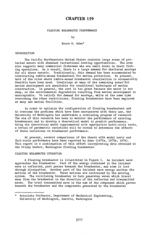
The measured and theoretically predicted transmission coefficient as
a function of frequency is shown in Figure 6.
The field data was high-pass filtered with a cutoff frequency of 0.05
Hertz in order to remove the influence of tidal variations or wave buoy
5. FLOATING BREAKWATER 2781
motions. After initial processing the data were directly transformed using
fast Fourier transformation procedures and smoothed by averaging adjacent
raw spectral components. The complete details of data analysis are contained
in Adee, Richey and Christensen (1976).
Extensive comparisons between theory and experiment have shown that the
hydrodynamic theory is excellent so long as roll motions are small. In the
frequency regions where the theory predicts higher roll motions the trans-
mission coefficient may be in error. This is because nonlinear damping is an
important factor in determining roll motion. Nonlinear damping is not included
in the theory but may be artificially approximated. Experience has shown that
by arbitrarily doubling the calculated hydrodynamic damping, better agreement
is produced. Damping has been doubled for the theoretical, prediction pre-
sented in Figure 6.
One advantage of the theory is that it doesn't simply produce a
transmission coefficient, but produces sufficient information to deterine
what factors have an effect on the wave transmission. For the Friday Harbor
floating breakwater as for other floating breakwaters the very low frequency
waves are unaffected by the structure's presence yielding a transmission
coefficient of nearly unity. The first trough in ths transmission coeffi-
cient at about 0.3 Hertz results from heave-and roll-generated waves can-
celling the fixed-body wave transmission. This transmission coefficient
is well below the transmission coefficient which would be obtained with
the breakwater rigidly restrained and only fixed-body transmission waves
passing through. As frequency increases, there is a peak at about 0.38.
At this point, the heave-generated wave has almost vanished, and the fixed-
body transmission is also small. The larger predicted transmission coeffi-
cient is primarily the result of a roll-generated wave with a smaller com-
ponent resulting from sway motion. The next trough at 0.43 occurs as the
heave motion-generated wave increases and cancels the roll and sway motion-
generated components. The fixed-body transmission is very small at 0.43.
As frequency increases above 0.43 the transmitted wave is almost totally
a result of the sway motion of the breakwater.
Another result of great interest to the designer is the force in the
mooring lines. In presenting this data a mooring force coefficient is
used which is defined as the amplitude of the force oscillation divided by
the incident wave amplitude times the weight per unit length of the break-
water.
The mooring-force coefficient for the seaward mooring line of the
Friday Harbor breakwater is shown in Figure 7. Here again, the field data
has been high pass filtered to eliminate tidal effects and also a low fre-
quency spike which occurs in the mooring-force spectrum. The theoretical
prediction is based on computing the spring constants for the three degrees
of freedom, multiplying these by the motions and summing force components.
From the designers standpoint, the theory predicts the trends accurately
and the overprediction at the peak would add to the margin of safety.
The main conclusion which should be reached from these results is
that it is possible to measure the performance of floating breakwaters in
6. 2782 COASTAL ENGINEERING-1976
the field and that the theory which has been developed predicts the trends
of the data and can play a very useful role in design.
PROBLEM OF COMPARISON
The floating breakwater at Friday Harbor, Washington represents one
type of breakwater which provides protection by reflecting the energy con-
tained in the incident wave. Other, more compliant breakwaters have been
proposed which provide protection by dissipating this energy or by setting
up waves which "interfere" with the incident wave. Still other proposed
breakwaters attempt to reduce the energy in the incident wave by forcing it
to break over some obstacle. Because these concepts are quite different
and because few have been tested at prototype scale, a rational comparison
of performance is quite difficult with the data presently available.
Clearly, from a users point of view, the breakwater offering the best per-
formance for the least cost would be the most attractive.
To present the performance of various types of floating breakwaters in
terms of performance per dollar is very difficult. There has been a great
variation in the cost of the floating breakwaters constructed to date, even
among those of the same type. Besides, with the diversity of materials
available and the rapid fluctuations in their prices which has recently taken
place, such information would rapidly become obsolete.
In the course of the study of floating breakwaters at the University of
Washington, we have often used beam divided by wavelength as the parameter
which characterizes the size of the breakwater. This seems to work well so
long as the discussion is centered on breakwaters which protect primarily
by reflection. When different types such as the reflecting and tethered
float breakwater are to be compared using beam to wavelength is inadequate.
An alternative procedure which seems to have merit is to use the
square root of the underwater volume per unit length divided by the wave-
length as the independent variable. If we are to ever be able to draw fair
general comparisons among proposed floating breakwaters,a consistent scheme
for presenting performance data should be developed.
NONLINEAR BEHAVIOR
Figure 8 shows a recorded time history of the mooring forces measured
at the Tenakee, Alaska floating breakwater. Looking at this figure one can
observe an oscillation with a period of about 60 seconds superimposed on
the expected shorter period oscillations.
The linear theoretical model permits the system to respond only at the
frequency of the incident wave. In order to explain the presence of these
long-period oscillations, nonlinearities must be included in the analysis.
To perform a mathematically complete analysis including all nonlinear effects
is beyond the present state of the art. However, in the case of the float-
ing breakwater, one can show that if two incident waves are considered and
second-order terms are retained, then an exciting force is present at the
difference between the frequencies of the incident waves. Normally, this
7. FLOATING BREAKWATER 2783
small exciting force would have little effect. Since the structure is only
lightly restrained in sway, the natural period is very long for sway motion.
The existence of a small exciting force at the sway natural frequency could
explain the large oscillation in mooring force.
Because the mooring lines are critical to floating breakwater survival
in extreme storm conditions, further research effort on the long-period
oscillations is justified.
ACKNOWLEDGEMENT
Financial support for floating breakwater research at the University
of Washington has been provided by the U.S. Army Corps of Engineers Coastal
Engineering Research Center and through the National Oceanic and Atmos-
pheric Administration Sea Grant Program. Their support is gratefully
acknowledged.
REFERENCES
Adee, B.H., "Analysis of Floating Breakwater Performance," Proceedings of
the Symposium on Modeling Techniques, San Francisco, Calif., 3-5
September 1975a.
Adee, B.H., "Floating Breakwater: An Idea Whose Time Has Returned," IEEE-MTS
Annual Meeting, Ocean '75, San Diego, Calif., September 1975b.
Adee, B.H., "Floating Breakwater Mooring Forces," Ocean Engineering Mechanics,
Am. Soc. of Mechanical Engineers, New York, 1975c.
Adee, B.H., "A Review of Developments and Problems in Using Floating Break-
waters," Offshore Technology Conference, Houston, Texas, May 1976.
Adee, B.H., Richey, Ep., Christensen, D.R., "Floating Breakwater Field
Assessment Program, Friday Harbor, Washington," Final Contract
Report submitted to U.S. Army Corps of Engineers Coastal Engineering
Research Center, July 1976.
Christensen, D.R., Richey, E.P., "Prototype Performance Characteristics
of Two Floating Breakwaters," Offshore Technology Conference, Houston,
Texas, May 1976.
13. FLOATING BREAKWATER 2789
X ,—,
W)
G
tl> •H
cd, o IX
CO
o
00
r-.
oo 1
UH
6 •fl
^
o
o
<D
H
r-
1
—'
6 0
•p
(8
S
J^
rt
CD
o
n
,£>
o ^1
O
Xi
^
nJ
M
X
in x
6 >- •H
o ^1
z ft,
UJ
ZD t*
^ Q O
• LU
O oc •p
U- B
(0
•H
U
•H
00 <4-l
f (1)
O O
O
c
o
•H
VI
CM trt
•H
6 a
CO CO ^
6 6 6
1N3I3IJJ300 NOISSIWSNtWi
o