SlideShare ist ein Scribd-Unternehmen logo
1 von 28
Downloaden Sie, um offline zu lesen
US Water Systems Fusion
Superfilters
Chemsorb, Calcite,
Carbon, Bone Char and
Katalox-Light
REVISION # 1.2
REVISION DATE October 23, 2014
1. Read all instructions carefully before operation.
2. Avoid pinched o-rings during installation by applying (provided with install kit) NSF
certified lubricant to all seals.
3. This system is not intended for treating water that is microbiologically unsafe or of
unknown quality without adequate disinfection before or after the system.
US Water Systems
1209 Country Club Road
Indianapolis, IN 46234
1-800-608-8792
WWW.USWATERSYSTEMS.COM
Owners
Manual
2
Safety Guide
 Check and comply with your provincial /
state and local codes. You must follow
these guidelines.
 Use care when handling the filter tank. Do
not turn upside down, drop, drag or set on
sharp protrusions.
 The system works on 12 volt-60 Hz electri-
cal power only. Be sure to use only the in-
cluded transformer.
 Transformer must be plugged into an in-
door 120 volt, grounded outlet only.
 WARNING: This system is not intend-
ed for treating water that is microbiologi-
cally unsafe or of unknown quality without
adequate disinfection before or after the
system.
For your safety, the information in this manual must be followed to minimize the risk of elec-
tric shock, property damage or personal injury.
Be sure to check the entire unit for any shipping damage or missing parts. Also note damage
to the shipping cartons. Contact US Water Systems at 1-800-608-8792 for all damage and
loss claims. A damage claim must be made within 24 hours of receipt of the unit or the claim
may not be honored.
Small parts, needed to install the softener, are in a parts bag. To avoid loss of the small
parts, keep them in the parts bag until you are ready to use them.
Unpacking / Inspection
PAGE
Unpacking / Inspection 2
Safety Guide 2
Proper Installation 3
Specification 4
Before Starting Installation 6
Sizing Requirements 6
Filter Preparation 8
Installation Instructions 11
System Start Up 15
Programming Instructions 16
About The System 17
Maintenance 18
Main Repair Parts 19
Trouble Shooting 26
Pressure Gauge Installation Drawing 27
Warranty 28
Table of Contents
3
Proper Installation
This water filter system must be properly installed and located in accordance with the
Installation Instructions before it is used.
 Do not install or store where it will not be
exposed to temperatures below freezing or
exposed to any type of weather. Water
freezing in the system will break it. Do not
attempt to treat water over 100°F.
 Do not install in direct sunlight. Excessive
sun or heat may cause distortion or other
damage to non-metallic parts.
 Properly ground to conform with all gov-
erning codes and ordinances.
 Use only lead-free solder and flux for all
sweat-solder connections, as required by
state and federal codes.
 Maximum allowable inlet water pressure is
125 psi. If daytime pressure is over 80 psi,
night time pressure may exceed the maxi-
mum. Use a pressure reducing valve to
reduce the flow if necessary.
 WARNING: Discard all unused parts and
packaging material after installation. Small
parts remaining after the installation could
be a choke hazard.
Overall
System
Inlet-Outlet
Connection
Height
C
Tank
B
A
Model Tank Size A B C
FSF-150 10” X 54” 60.25” 57.25” 10”
FSF-200 12” X 52” 58.25” 55.25” 12”
FSF-250 13” X 54” 60.25” 57.25” 13”
FSF-300 14” x 65” 72.25” 68.25” 14”
FSF-400 16” x 65” 72.25” 68.25” 16”
FSF-500 18” x 65” 72.25” 68.25” 16”
4
Specifications
5
Specifications
 Continuous operation at flow rates greater than the ser-
vice flow rate may affect capacity and efficiency perfor-
mance.
 The manufacturer reserves the right to make product
improvements which may deviate from the specifications
and descriptions stated herein, without obligation to
change previously manufactured products or to note the
change.
 Peak flow rates are intended for intermittent use only and
are for residential application only
 At the stated service flow rates, the pressure drop
through these devices will not exceed 15 psig
6
Before Starting Installation
Tools, Pipe, and Fittings, Other Materials
 Pliers
 Screwdriver
 Teflon tape
 Razor knife
 Two adjustable wrenches
 Additional tools may be required if modifi-
cation to home plumbing is required.
 Plastic inlet and outlet fittings are included
with the filter. To maintain full valve flow,
3/4” or 1” pipes to and from the filter fittings
are recommended. It is important to main-
tain the same, or larger, pipe size as the
water supply pipe, up to the softener inlet
and outlet.
 Use copper, brass, or PEX pipe and fit-
tings.
 Some codes may also allow PVC plastic
pipe.
 ALWAYS install the included bypass valve,
or 3 shut-off valves. Bypass valves let you
turn off water to the filter for repairs if
needed, but still have water in the house
pipes.
 5/8” OD drain line is needed for the valve
drain.
Sizing Requirements
Water Pressure
The water system must have a pump large enough to deliver the recommended backwash
rate with a minimum pressure at the inlet of the filter of 30 psi. If the existing system cannot
do this, it must be upgraded to do so. Whenever possible, the water system should be ad-
justed to deliver at least 30 psi for even more satisfactory results.
Backwash Flow Rates
The most important criteria in sizing a filter is the capacity of the pump. The water must pass
through the filter media at the proper service flow rate. The filter must also be backwashed
at a flow rate sufficient to dislodge and remove the captured particles. Failure to provide
sufficient water will cause a build-up of particles in the filter media, impairing its ability. In
order for your filter to backwash and rinse properly, your pump must be capable of providing
the backwash flow rates indicated on page 4 & 5.
7
 Place the filter tank as close as possible to
the pressure tank (well system) or water
meter (city water).
 Place the filter tank as close as possible to
a floor drain, or other acceptable drain
point (laundry tub, sump, standpipe, etc.).
 Connect the filter to the main water supply
pipe BEFORE the water heater. DO NOT
RUN HOT WATER THROUGH THE FIL-
TER. Temperature of water passing
through the filter must be less than 100
deg. F.
 Do not install the filter in a place where it
could freeze. Damage caused by freez-
ing is not covered by the warranty.
 Put the filter in a place water damage is
least likely to occur if a leak develops. The
manufacturer will not repair or pay for wa-
ter damage.
 A 120 volt electric outlet, to plug the includ-
ed transformer into, is needed within 6 feet
of the filter. The transformer has an at-
tached 6 foot power cable. Be sure the
electric outlet and transformer are in an
inside location, to protect from wet
weather.
 If installing in an outside location, you must
take the steps necessary to assure the fil-
ter, installation plumbing, wiring, etc., are
as well protected from the elements, con-
tamination, vandalism, etc., as when in-
stalled indoors.
 Keep the filter out of direct sunlight.
The sun’s heat may soften and distort
plastic parts.
Where To Install The Filter
8
Filter Preparation
Fusion Backwashing Filter Tank Installation Instructions
WATER PRESSURE: A minimum of 20 pounds of water pressure is required for regeneration valve to oper-
ate effectively.
ELECTRICAL FACILITIES: An uninterrupted alternating current (A/C) supply is required. Note: Other volt-
ages are available. Please make sure your voltage supply is compatible with your unit before installation.
EXISTING PLUMBING: Condition of existing plumbing should be free from lime and iron buildup. Piping
that is built up heavily with lime and/or iron should be replaced.
LOCATION OF FUSION NLT TANK AND DRAIN: The Infusion tank should be located close to a drain to
prevent air breaks and back flow.
CAUTION: Water pressure is not to exceed 80 psi, water temperature is not to exceed 110°F (43°C), and
the unit cannot be subjected to freezing conditions.
Media Installation
1) Remove the tank from carton.
2) Verify the riser tube is centered in the bottom center of the tank. A flashlight may be
necessary. The distributor tube will be flush with the top of the tank when it is cen-
tered.
9
Filter Preparation
3) Place a piece of duct tape over the riser tube so no media enters the riser while filling.
4) Use the Blue Funnel provided, to pour the gravel and media into the tank. Pour the grav-
el into the tank first, then the media. Pour the gravel and media evenly around the hole to
ensure it is well distributed in the tank and pour slow enough, to keep from plugging the
hole. A helper may be needed to hold the funnel during the filling process. It is recom-
mended that a dust mask and safety goggles be worn to prevent possible injury. A shop
vacuum can be used to capture dust during the filling procedure. Pour all the gravel and all
the media shipped with the unit into the tank. US Water does not send extra/unused me-
dia.
5) When media is installed move tank side to side to settle the media. Remove the funnel
and tape from the distributor tube.
10
Filter Preparation
6) Lubricate the distributor O-ring and the tank O-ring on the bottom of the control valve.
Then install the upper basket on the bottom of the valve by lining up the tabs then turning
the basket clockwise to lock it in place. Place the upper basket over the distributor tube
and push the valve on the tank. Thread the valve on the tank by turning it clockwise. Be
sure not to cross-thread the valve on the tank. Tighten the valve hand tight, then snug it
further by tapping it with the palm of the hand. DO NOT use tools to tighten the valve or
damage could occur.
11
Installation Instructions
1. If your hot water tank is electric, turn off the power to it to avoid damage to the element in
the tank.
2. If you have a private well, turn the power off to the pump and then shut off the main water
shut off valve. If you have municipal water, simply shut off the main valve. Go to the fau-
cet, (preferably on the lowest floor of the house) turn on the cold water until all pressure is
relieved and the flow of water stops.
3. Locate the filter tank close to a drain where the system will be installed. The surface
should be clean and level.
4. Connect the inlet and outlet of the filter using appropriate fittings. Perform all plumbing
according to local plumbing codes. Pressure gauges should be added in some applica-
tions. There is a drawing on page 27 that shows gauge location.
 ON COPPER PLUMBING SYSTEMS BE SURE TO INSTALL A GROUNDING
WIRE BETWEEN THE INLET AND OUTLET PIPING TO MAINTAIN GROUNDING
WHEN APPLICABLE.
Any solder joints being soldered near the valve must be done before connecting any piping
to the valve. Always leave at least 6" (152 mm) between the control valve and joints being
soldered when soldering pipes that are connected to the valve. Failure to do this could
cause damage to the valve.
The Fusion Backwashing Filter is equipped with 1” removable connectors. It is recommend-
ed that these connectors are installed in the plumbing fitting using Teflon tape then lubricate
the o-ring on the connector. Remove the red clips and push the connectors into the bypass
valve once they are tight in the plumbing fitting. The red clips can then be re-installed to se-
cure the connectors in the bypass valve.
The inlet and outlet can be identified on the bypass valve. There are arrows stamped in the
bypass valve showing flow (See page 18 diagram). The arrow pointing toward the valve is
the inlet and the arrow pointing away from the valve is the outlet.
All piping should be secured to prevent stress on the bypass valve and connectors.
12
Hose barb fitting for drain line.
Be sure to use a hose clamp to
secure the line.
5. Connect the drain hose to the filter valve and secure it with a hose clamp. Run the drain
hose to the nearest laundry tub or floor drain. This can be ran overhead or down along the
floor. Drain hose should be a minimum of 1/2”. If running the drain line more than 20 ft
overhead, it is recommended to increase the hose size to 3/4”. A DIRECT CONNECTION
INTO A WASTE DRAIN IS NOT RECOMMENDED. A PHYSICAL AIR GAP OF AT LEAST
1.5” SHOULD BE USED TO AVOID BACTERIA AND WASTEWATER TRAVELING BACK
THROUGH THE DRAIN LINE INTO THE FILTER.
Be sure to secure the drain line. The softener will drain with force and it should be
secured to prevent a leak. Hose clamps should be used to secure the drain line at the
connection points.
Installation Instructions
13
Installation Instructions
6. Using the Allen Key (included), place the unit in the bypass position (See page 18 for by-
pass valve handle placement). Slowly turn on the main water supply. At the nearest cold
treated water tap nearby remove the faucet screen, open the faucet and let water run a few
minutes or until the system is free of any air or foreign material resulting from the plumbing
work.
7. Make sure there are no leaks in the plumbing system before proceeding. Close the water
tap when water runs clean.
8. Proceed to start up instructions.
Note: The unit is not ready for service until you complete the start-up instructions.
14
Filter Installation
15
System Start-Up
1. Plug the valve into an approved power source.
2. When power is supplied to the control, the screen will display “INITIALIZING WAIT
PLEASE” while it finds the service position.
3. Start an Immediate Manual Regeneration. The valve will immediately start moving to the
BACKWASH position.
4. Partially open the inlet on the bypass valve slowly and allow water to enter the unit. Allow
all air to escape from the unit before turning the water on fully then allow water to run to
drain for 3-4 minutes or until all media fines are washed out of the softener indicated by
clear water in the drain hose.
KATALOX SYSTEMS SHOULD BE BACKWASHED FOR A MINIMUM OF 1 HOUR. IN
SOME CASES ADDITIONAL RINSING MAY BE NEEDED. For Katalox filters, when the
valve is in the backwash position, unplug the power cord for the valve. This will keep the
unit in the backwash cycle. Allow the system to backwash for 1 hour, then plug the power
cord back in and go to step 5. All other media types can use the general backwash in Step
4.
5. Press any button to advance to the RINSE position. Slowly open the bypass inlet valve
during the rinse cycle until it is fully opened. Check the drain line flow. Allow the water to
run for 3-4 minutes or until the water is clear.
6. The valve will automatically advance to the SERVICE position after the RINSE cycle is
complete. Open the outlet valve on the bypass, then open the nearest treated water fau-
cet and allow the water to run until clear, close the tap and replace the faucet screen.
7. Program time, date, and number of days between regenerations into controller using the
following Programming Instructions
Start-up Instructions
Key Pad Configuration
SET-
TINGS
This function is to enter the basic set up
information required at the time of installa-
tion.
MANUAL
REGEN
This function is to initiate an immediate or
delayed manual regeneration.
DOWN /
UP
Increase or decrease the value of the set-
tings while in the programming mode.
DELAYED REGENERATION
Press and release the MANUAL REGEN.
Button to set a delayed regeneration that will
occur at the regeneration time. The main dis-
play page will show DELAYED REGEN ON.
To cancel press and release the MANUAL
REGEN. Button. The main display page will
show DELAYED REGEN OFF.
IMMEDIATE REGENERATION
To start an immediate regeneration (or step
valve through each position), press and hold
the MANUAL REGEN. Button for 3 seconds
(until beeps). The valve will start an immedi-
ate regeneration. Press any key to skip to
the next cycle.
Manual Regeneration (Step / Cycle Valve)
16
Backwash Frequency
Programming Instructions
TIME OF DAY, YEAR, MONTH, DAY,
Time of day is for normal operation of system and the scheduling of the re-
generation time. The date is used in a diagnostic function to track the last
time the system regenerated.
REGEN DAYS
This value is the number of days between regenerations or back washes to
clean the filters.
GALLONS
Default value is OFF. This should not be changed.
REGEN TIME
This setting determines the time of day to perform a scheduled regenera-
tion. The normal regen time for a filter is 12:00 AM.
Settings
Press SETINGS key (3 SECONDS / BEEP)
VALVE MODE
B.W. FILTER
TIME OF DAY
12:01 PM
YEAR
2012
MONTH
AUGUST
DAY
21
REGEN DAYS
3 DAYS
GALLONS
OFF
REGEN TIME
12:00 AM
PROGRAMMING
COMPLETE
Contact US Water Systems at 1-800-608-8792 to help with the backwash frequency setting.
This can be adjusted by the home owner to suite their individual needs with frequencies
available from 1 – 99 days.
17
Control Operation During A Power Failure
In the event of a power failure, the valve will keep track of the time and day for 48 hours.
The programmed settings are stored in a non-volatile memory and will not be lost during a
power failure. If power fails while the unit is in regeneration, the valve will finish regenera-
tion from the point it is at once power is restored. If the valve misses a scheduled regenera-
tion due to a power failure, it will queue a regeneration at the next regeneration time once
power is restored.
Main Display
About The System
Periodically the filter will require a back wash to clean the trapped particles and unpack the
filter bed to restore the system flow rates. The table below explains the regeneration steps.
Regeneration Process
Step Name Description
#1 Back Wash
Fresh water is introduced to the bottom of the tank flowing upwards expanding
the filter media to rinse out any dirt or small particles to the drain and to un-
compact the bed to restore full service flow rates.
#2 Rinse
Fresh water is introduced from the top of the tank flowing down through the
filter bed rinsing any unfiltered water to the drain.
The main display page will pause on the Date and Time page for 5 seconds. Then it will
continually scroll through all of the system diagnostic display pages. Depending on the
Valve Type some pages will not be displayed. To manually scroll through the diagnostics,
press the down or up key. To reset the TOTAL REGENS, TOTAL GALLONS OVER RUN
TOTAL, or PEAK flow rates, press and hold the MENU until the value changes to zero.
PARAMETER DESCRIPTION
JULY/17/2012
8:30 PM
TOTAL 1,500 GAL
REMAIN 1,200 GAL
LAST REGEN
9/24/12
TOTAL REGENS
10
TOTAL GALLONS
001590 GAL
TOTAL 4 DAYS
REMAIN 3 DAYS
OVER RUN TOTAL
0000 GAL
CURRENT 1.5 GPM
PEAK 6.5 GPM
DELAYED REGEN
OFF
REGEN TIME
12:00 AM
VALVE MODE
B.W. FILTER
The current setting for regeneration time.
The current setting of the valve mode.
The total number of regenerations.
The total amount of gallons treated by the system.
The total amount of water that has exceeded the system capacity over the last 4
regenerations. When remaining goes to zero, the gallons used will be added to over run total.
The current flow rate and the peak flow rate since the last regeneration.
Advises whether a delayed regeneration has been scheduled manually or automatically.
Month, Day, Year, Time
The number of days remaining before regeneration. This option is only in filter mode.
The total amount is the system capacity when fully regenerated. The remaining is the
capacity left in the system.
The date of the last regeneration.
18
Automatic Raw Water Bypass During Regeneration
The regeneration cycle can last 30 minutes after which filtered water service will be restored.
During regeneration, un-filtered water is automatically bypassed for use in the household.
Hot water should be used as little as possible during this time to prevent un-filtered water
from filling the water heater. This is why automatic regeneration is set for sometime during
the night and manual regenerations should be performed when little or no water will be used
in the household.
Normal regeneration time is 2:00 AM.
New Sounds
You may notice new sounds as your filter operates. The regeneration cycle lasts up to 30
minutes. During this time, you may hear water running intermittently to the drain.
Manual Bypass
In the case of emergency you can isolate your water filter from the water supply using the
bypass valve located at the back of the control. In normal operation the bypass is open with
the on/off knobs in line with the inlet and outlet pipes.
To isolate the filter, simply rotate the knobs clockwise (as indicated by the word BYPASS
and arrow) until they lock. You can use your water related fixtures and appliances as the wa-
ter supply is bypassing the filter. However, the water you use will be hard. To resume water
service, open bypass valve by rotating the knobs counterclockwise.
Maintenance
Maintenance of your new water filter requires very little time or effort but it is essential. Reg-
ular maintenance will ensure many years of efficient and trouble-free operation.
1. Periodically make sure your pump is performing satisfactorily to ensure sufficient water is
available for backwashing the filter.
2. Periodically test your raw and filtered water to ensure conditions are still the same for
your original settings and that the unit is working they way it is intended to. Water testing
is often the best way to determine when the filter media will require replacement.
3. Periodically check that the drain line is clear and free from any obstructions.
19
Main Repair Parts
Replacement Part Number Part Description DWG # Quantity
60010052 POWER TRANSFORMER 120V-12V A 1
60010002 BYPASS / METER B 1
10010063 485 UP DOWN FLOW FILTER VALVE C 1
60010048 TOP CONE D 1
25020041 844 TANK (75) E 1
25020042 948 TANK (100) E 1
25020043 1054 TANK (150) E 1
25010058 1252 TANK (200) E 1
25030007 1465 TANK (300) E 1
50010005 DISTRIBUTOR 1X54 F 1
REPLACEMENT PARTS - FILTER
Replacing Drain Line Flow Control (DLFC)
1. Remove the red clip that secures the drain line elbow.
2. Remove the BLFC washer from the elbow fitting.
3. Reassemble using the reverse procedure.
20
Filter Exploded View
21
A A A
B
D
F
E
A
C
Replacement Part Number Part Description DWG # Quantity
60010020 3/4" NPT ELBOW A 2
60010019 1" NPT STRAIGHT A 2
60010023 3/4" NPT STRAIGHT A 2
60010079 VALVE COUPLING INLET B 1
60010101 VALVE COUPLING OUTLET (METER SIDE) C 1
60010025 PLASTIC SECURE CLIP D 2
60010046 BYPASS SS CLIP E 2
60010047 BYPASS SS SCREW F 2
REPLACEMENT PARTS - CONNECTORS
Main Repair Parts - Connectors
22
VALVE REPAIR PARTS LIST
Replacement
Part Number
Part Description
Replacement
Part Number
Part Description
60010127 INJECTOR SET #0000 BLACK 60010129 85HE UPFLOW PISTON ASSEMBLY
60010126 INJECTTOR SET #000 GREY 60010171 85HE DOWNFLOW PISTON ASSEMBLY
60010035 INJECTOR SET #00 VIOLET 60010130 85HE SEAL & SPACER KIT
60010034 INJECTOR SET #0 RED 60010131 85HE DLFC #1 1.5 GPM
60010033 INJECTOR SET #1 WHITE 60010132 85HE DLFC #2 2.0 GPM
60010032 INJECTOR SET #2 BLUE 60010133 85HE DLFC #3 2.4 GPM
60010031 INJECTOR SET #3 YELLOW 60010135 85HE DLFC #5 3.5 GPM
60010128 BLFC 0.2 GPM 60010136 85HE DLFC #A 5.0 GPM
60010110 BLFC 0.3 GPM 60010137 85HE DLFC #B 7.0 GPM
60010082 BLFC 0.7 GPM 60010138 85HE DLFC #C 10.0 GPM
Control Valve Exploded View
23
485HE CONTROL VALVE (DOWNFLOW)
Replacement
Part Number
MFG Part Number Part Description DWG # Quantity
5056087 Screw-M5x12(Hexagon) A01 3
5056088 Screw-M5x16(Hexagon With Washer) A02 2
5056047 End Plug Retainer A03 1
5031016 BNT85HE Piston Rod A04 1
5056097 Piston Pin A05 1
5031015 BNT85HE Quad Ring Plug Cover A06 1
5056070 Quad Ring A07 2
5031011 BNT85HE End Plug A08 1
5031014 BNT85HE Piston Retainer A09 1
5057001 BNT85HE Piston(Electrical Downflow) A10 1
5056073 Seal A11 5
5056021 Spacer A12 4
5010082 Drain Fitting-B A13 1
5031005 BNT85HE Spacer A14 1
5056186 DLFC-2# A15 1
5056172 Secure Clip-s A16 2
5031002 BNT85HE Valve Body A17 1
5056508 Screw-M5x12(Hexagon With Washer) A18 5
5030004 BNT85 End Cover A19 1
5030013 O-Ring-¢30×2.65 A20 1
5056063 O-Ring-¢78.74×5.33 A21 1
26010103 O-Ring-¢25×3.55 A22 1
7060007 Valve Bottom Connector A23 1
13000426 Screw-ST2.9X13(Large Washer) A24 2
5031022 O-Ring-¢32×3 A25 1
5031021 O-Ring-¢18×3 A26 1
5031013 Injector Plug Body A27 1
30110007 Plastic Ball ¢6 A28 1
30040089 Injector Throat A29 2
5031012 BNT85HE Injector Fixed Sleeve A30 1
30040090 Injector Nozzle A31 2
5056103 Injector Screen A32 1
5031003 BNT85HE Injector Cover Body A33 1
5031018 O-Ring-¢40×2.65 A34 1
5031004 BNT85HE Injector Cover Cap A35 1
5031027 Screw-M5x25(Hexagon With Washer) A36 4
5056075 Seal Mat A37 1
5056134 O-Ring-¢12×2 A38 3
5056054 Injector Stem A39 1
5056031 Injector Spacer A40 1
5056081 O-Ring-¢12.5×1.8 A41 1
5056030 Injector Cap A42 1
5056093 Injector Screen A43 1
5010049 Special Washer A44 1
5056105 Retaining Ring A45 1
5031010 BNT85HE BLFC Fixed Sleeve A46 2
5056076 BLFC-2# A47 1
5005629 Injector Fitting(3/8".Elbow) A48 1
Control Valve Parts List
24
Power Head Exploded View
25
485HE POWER HEAD (DOWNFLOW)
Replacement
Part Number
MFG Part Number Part Description DWG # Quantity
5056084 Screw-ST3.5X13 B01 10
5010037 Screw-ST2.9X10 B02 9
13000416 Screw-ST3.5X25 B03 1
5031007 BNT85HE Piston Rod Guide Plate B04 1
5056510 Motor-12v/2rpm B05 1
5030014 Motor Power Cable 1
11700005 Wire Connector 2
5056098 Motor Pin B06 1
5031006 BNT85HE Mounting Plate B07 1
5030009 BNT85 Drive Gear B08 1
13000426 Screw-ST2.9X13(Large Washer) A24 2
5056139 Washer-3x13 B09 1
5030007 BNT85 Main Gear B10 1
5030005 BNT185 Housing B11 1
5031017 BNT85HE Brine Gear(Downflow) B12 1
5010023 Magnet(3×2.7) B13 1
5056141 Washer-4x12 B14 1
5056166 Screw-ST4.2X12(Large Washer) B15 1
5031016 BNT85HE Piston Rod A04 1
5010036 Screw-ST3.5X16 B16 1
5031026 BNT85HE Main Pcb(Downflow) B17 1
5010031 Meter Assembly 1
5010046 Meter Strain Rlief 1
5010029 Power Cable 1
5010035 Power Strain Rlief 1
19010105 Wire Rope-3×100 2
5031024 BNT85HE Display(Downflow) B18 1
5030021 BNT85 Wiring Harness 1
5030003 BNT85 Cover B19 1
Power Head Parts List
26
Trouble Shooting
Issue Possible Cause Possible Solution
1. No power supply. Check electrical service, fuse, etc.
2. Defective circuit board. Replace faulty parts.
3. Power failure. Reset time of day.
1. By-pass valve open. Close by-pass valve.
2. Electrical service to unit has been
interrupted
Assure permanent electrical service (check
fuse, plug or switch)
3. Defective or stripped media bed Replace media
4. Quality of water has worsened Have water sample analyzed to determine
any change
5. Filter capacity too small Replace with larger unit or add another
filter
6. Filter not backwashing enough Be sure control is not clogged or drain
line restricted. Be sure water pressure
has not dropped and that pump has
sufficient capacity.
7. Leak between valve and central tube. Check if central tube is cracked or o-ring is
damaged. Replace faulty parts.
8. Internal valve leak. Replace valve seals, spacer, and piston
assembly.
1. Iron or scale build up in line feeding unit. Clean pipes.
2. Iron build up inside valve or tank. Clean control and add resin cleaner to clean
bed. Increase regeneration frequency.
3. Inlet of control plugged due to foreign
material.
Remove piston and clean control valve.
1. Air in water system. Check well system for proper air eliminator
control.
2. Incorrect drain line flow control (DLFC)
button.
Check for proper flow rate.
E. Valve continuously cycles. 1. Defective position sensor PCB. Replace faulty parts.
1. Valve settings incorrect. Check valve settings.
2. Foreign material in control valve. Clean control.
3. Internal leak. Replace seals, spacers, and piston assembly.
F. Flow to drain continuously.
A. Unit fails to initiate a
regeneration cycle.
B. FILTER BLEEDS TASTE
AND ODOR OR SEDIMENT
C. Low water pressure.
D. Filter media in drain line.
27
Pressure Differential Gauge Installation
28
For the lifetime of the original purchaser, at the original
residential place of installation of this Fusion Katalox Light
Superfilter Water Conditioning System, US WATER
SYSTEMS, INC. warrants the following:
LIFETIME COVERAGE
Media Tanks
Free of all costs to you except transportation and labor
charges, we warrant that we will replace or repair the
fiberglass media tank, if for any reason it is found to be
defective, because of faulty materials or workmanship.
SEVEN YEAR COVERAGE
Valve Assembly & Electronics
We warrant that for seven (7) years from the date of
purchase, we will replace the valve assemblies or
electronic components at no charge to you except for
transportation and standard labor charges. Electronics
damaged due to environmental issues or improper
installation are not covered.
GENERAL PROVISIONS
This warranty does not apply to any commercial or
industrial installations or to any part of the water
conditioner which has been subjected to misuse, neglect,
alteration or accident; or to any damage caused by fire,
flood, freezing, Acts of God, or any other casualty, or if the
original serial numbers have been removed.
These warranties are in lieu of all other warranties
expressed. or implied, and we do not authorize any person
to assume for us any other obligation on the sale of this
water conditioner. No responsibility is assumed for delays
or failure to meet these warranties caused by strike,
government regulations or other circumstances beyond the
control of US WATER SYSTEMS, INC..
TO OBTAIN WARRANTY SERVICE, CALL OR WRITE: US WATER
SYSTEMS, INC. 1209 COUNTRY CLUB ROAD INDIANAPOLIS,
IN 46234 (800) 608-USWA.
ANY IMPLIED WARRANTIES OF FITNESS OR
MERCHANTABILITY ARE LIMITED TO THE TERMS OF
THIS EXPRESSED WARRANTY AND THERE ARE NO
WARRANTIES WHICH EXTEND BEYOND THOSE
HEREIN. US WATER SHALL NOT BE LIABLE FOR ANY
INCIDENTIAL OR CONSEQUENTIAL DAMAGES.
SOME STATES DO NOT ALLOW THE EXCLUSION OR
LIMITATIONS OF INCIDENTAL OR CONSEQUENTIAL
DAMAGES SO THE ABOVE LIMITATION MAY NOT
APPLY TO YOU. THIS WARRANTY GIVES YOU
SPECIFIC LEGAL RIGHTS, AND YOU MAY ALSO HAVE
OTHER RIGHTS WHICH VARY FROM STATE TO
STATE.
THIS WARRANTY MAY BE TRANSFRRED TO A
SUBSEQUENT OWNER WITH WRITTEN APPROVAL OF
US WATER AND PAYMENT OF STANDARD TRANSFER
FEE.
Limited Lifetime Warranty

Weitere ähnliche Inhalte

Ähnlich wie Colorado Water Purification US Water Fusion Backwashing Filter Manual 1110 8 14

MangOX Air Charger 2510 iron Filter Installation and Start-up Guide
MangOX Air Charger 2510 iron Filter Installation and Start-up GuideMangOX Air Charger 2510 iron Filter Installation and Start-up Guide
MangOX Air Charger 2510 iron Filter Installation and Start-up Guide
Clean Water Systems
 
High Through Put Homogenizer
High Through Put HomogenizerHigh Through Put Homogenizer
High Through Put Homogenizer
WISBIOMED
 
PRESENTATION ON SURGE ANTICIPATION VALVE.pptx
PRESENTATION ON SURGE ANTICIPATION VALVE.pptxPRESENTATION ON SURGE ANTICIPATION VALVE.pptx
PRESENTATION ON SURGE ANTICIPATION VALVE.pptx
holegajendra
 

Ähnlich wie Colorado Water Purification US Water Fusion Backwashing Filter Manual 1110 8 14 (20)

MangOX Air Charger 2510 iron Filter Installation and Start-up Guide
MangOX Air Charger 2510 iron Filter Installation and Start-up GuideMangOX Air Charger 2510 iron Filter Installation and Start-up Guide
MangOX Air Charger 2510 iron Filter Installation and Start-up Guide
 
MangOX Air Charger 2510 Iron Filter Installation and Start-up Guide
MangOX Air Charger 2510 Iron Filter Installation and Start-up GuideMangOX Air Charger 2510 Iron Filter Installation and Start-up Guide
MangOX Air Charger 2510 Iron Filter Installation and Start-up Guide
 
GRI WVS Data Sheet
GRI WVS Data SheetGRI WVS Data Sheet
GRI WVS Data Sheet
 
Intex krystalClear Pool Pump manual model 603 for Intex and Bestway swimming ...
Intex krystalClear Pool Pump manual model 603 for Intex and Bestway swimming ...Intex krystalClear Pool Pump manual model 603 for Intex and Bestway swimming ...
Intex krystalClear Pool Pump manual model 603 for Intex and Bestway swimming ...
 
RCA Seminar, Day 1, Greg Swartz, Ops A La Carte
RCA Seminar, Day 1, Greg Swartz, Ops A La CarteRCA Seminar, Day 1, Greg Swartz, Ops A La Carte
RCA Seminar, Day 1, Greg Swartz, Ops A La Carte
 
T50i installation guide from Firstbathrooms.co.uk
T50i installation guide from Firstbathrooms.co.ukT50i installation guide from Firstbathrooms.co.uk
T50i installation guide from Firstbathrooms.co.uk
 
Rain Director Install LQ
Rain Director Install LQRain Director Install LQ
Rain Director Install LQ
 
Krystal Clear Model 637R filter Pump Manual for Intex and bestway swimming pools
Krystal Clear Model 637R filter Pump Manual for Intex and bestway swimming poolsKrystal Clear Model 637R filter Pump Manual for Intex and bestway swimming pools
Krystal Clear Model 637R filter Pump Manual for Intex and bestway swimming pools
 
Aqua pump
Aqua pumpAqua pump
Aqua pump
 
farmtek Fodder syetem.pdf
farmtek Fodder syetem.pdffarmtek Fodder syetem.pdf
farmtek Fodder syetem.pdf
 
caldeira elétrica montada na parede
caldeira elétrica montada na paredecaldeira elétrica montada na parede
caldeira elétrica montada na parede
 
manual da caldeira elétrica
manual da caldeira elétricamanual da caldeira elétrica
manual da caldeira elétrica
 
caldeira elétrica
caldeira elétricacaldeira elétrica
caldeira elétrica
 
electric boiler
electric boiler electric boiler
electric boiler
 
105 _r0_1705_en
105  _r0_1705_en105  _r0_1705_en
105 _r0_1705_en
 
Top 10 Cross-Connection Hazards Threatening Your Drinking Water
Top 10 Cross-Connection Hazards Threatening Your Drinking WaterTop 10 Cross-Connection Hazards Threatening Your Drinking Water
Top 10 Cross-Connection Hazards Threatening Your Drinking Water
 
High Through Put Homogenizer
High Through Put HomogenizerHigh Through Put Homogenizer
High Through Put Homogenizer
 
PRESENTATION ON SURGE ANTICIPATION VALVE.pptx
PRESENTATION ON SURGE ANTICIPATION VALVE.pptxPRESENTATION ON SURGE ANTICIPATION VALVE.pptx
PRESENTATION ON SURGE ANTICIPATION VALVE.pptx
 
Pro‐Ox Iron Filter 1650 with Chlorine Side Tank Installation and Start Up Guide
Pro‐Ox Iron Filter 1650 with Chlorine Side Tank Installation and Start Up GuidePro‐Ox Iron Filter 1650 with Chlorine Side Tank Installation and Start Up Guide
Pro‐Ox Iron Filter 1650 with Chlorine Side Tank Installation and Start Up Guide
 
089414 2
089414 2089414 2
089414 2
 

Kürzlich hochgeladen

Call Girls Jp Nagar Just Call 👗 7737669865 👗 Top Class Call Girl Service Bang...
Call Girls Jp Nagar Just Call 👗 7737669865 👗 Top Class Call Girl Service Bang...Call Girls Jp Nagar Just Call 👗 7737669865 👗 Top Class Call Girl Service Bang...
Call Girls Jp Nagar Just Call 👗 7737669865 👗 Top Class Call Girl Service Bang...
amitlee9823
 
Quick Doctor In Kuwait +2773`7758`557 Kuwait Doha Qatar Dubai Abu Dhabi Sharj...
Quick Doctor In Kuwait +2773`7758`557 Kuwait Doha Qatar Dubai Abu Dhabi Sharj...Quick Doctor In Kuwait +2773`7758`557 Kuwait Doha Qatar Dubai Abu Dhabi Sharj...
Quick Doctor In Kuwait +2773`7758`557 Kuwait Doha Qatar Dubai Abu Dhabi Sharj...
daisycvs
 
Call Girls In Majnu Ka Tilla 959961~3876 Shot 2000 Night 8000
Call Girls In Majnu Ka Tilla 959961~3876 Shot 2000 Night 8000Call Girls In Majnu Ka Tilla 959961~3876 Shot 2000 Night 8000
Call Girls In Majnu Ka Tilla 959961~3876 Shot 2000 Night 8000
dlhescort
 
Call Girls in Delhi, Escort Service Available 24x7 in Delhi 959961-/-3876
Call Girls in Delhi, Escort Service Available 24x7 in Delhi 959961-/-3876Call Girls in Delhi, Escort Service Available 24x7 in Delhi 959961-/-3876
Call Girls in Delhi, Escort Service Available 24x7 in Delhi 959961-/-3876
dlhescort
 
Nelamangala Call Girls: 🍓 7737669865 🍓 High Profile Model Escorts | Bangalore...
Nelamangala Call Girls: 🍓 7737669865 🍓 High Profile Model Escorts | Bangalore...Nelamangala Call Girls: 🍓 7737669865 🍓 High Profile Model Escorts | Bangalore...
Nelamangala Call Girls: 🍓 7737669865 🍓 High Profile Model Escorts | Bangalore...
amitlee9823
 
The Abortion pills for sale in Qatar@Doha [+27737758557] []Deira Dubai Kuwait
The Abortion pills for sale in Qatar@Doha [+27737758557] []Deira Dubai KuwaitThe Abortion pills for sale in Qatar@Doha [+27737758557] []Deira Dubai Kuwait
The Abortion pills for sale in Qatar@Doha [+27737758557] []Deira Dubai Kuwait
daisycvs
 
Chandigarh Escorts Service 📞8868886958📞 Just📲 Call Nihal Chandigarh Call Girl...
Chandigarh Escorts Service 📞8868886958📞 Just📲 Call Nihal Chandigarh Call Girl...Chandigarh Escorts Service 📞8868886958📞 Just📲 Call Nihal Chandigarh Call Girl...
Chandigarh Escorts Service 📞8868886958📞 Just📲 Call Nihal Chandigarh Call Girl...
Sheetaleventcompany
 

Kürzlich hochgeladen (20)

Mysore Call Girls 8617370543 WhatsApp Number 24x7 Best Services
Mysore Call Girls 8617370543 WhatsApp Number 24x7 Best ServicesMysore Call Girls 8617370543 WhatsApp Number 24x7 Best Services
Mysore Call Girls 8617370543 WhatsApp Number 24x7 Best Services
 
Call Girls Jp Nagar Just Call 👗 7737669865 👗 Top Class Call Girl Service Bang...
Call Girls Jp Nagar Just Call 👗 7737669865 👗 Top Class Call Girl Service Bang...Call Girls Jp Nagar Just Call 👗 7737669865 👗 Top Class Call Girl Service Bang...
Call Girls Jp Nagar Just Call 👗 7737669865 👗 Top Class Call Girl Service Bang...
 
Quick Doctor In Kuwait +2773`7758`557 Kuwait Doha Qatar Dubai Abu Dhabi Sharj...
Quick Doctor In Kuwait +2773`7758`557 Kuwait Doha Qatar Dubai Abu Dhabi Sharj...Quick Doctor In Kuwait +2773`7758`557 Kuwait Doha Qatar Dubai Abu Dhabi Sharj...
Quick Doctor In Kuwait +2773`7758`557 Kuwait Doha Qatar Dubai Abu Dhabi Sharj...
 
Call Girls Ludhiana Just Call 98765-12871 Top Class Call Girl Service Available
Call Girls Ludhiana Just Call 98765-12871 Top Class Call Girl Service AvailableCall Girls Ludhiana Just Call 98765-12871 Top Class Call Girl Service Available
Call Girls Ludhiana Just Call 98765-12871 Top Class Call Girl Service Available
 
Call Girls In Majnu Ka Tilla 959961~3876 Shot 2000 Night 8000
Call Girls In Majnu Ka Tilla 959961~3876 Shot 2000 Night 8000Call Girls In Majnu Ka Tilla 959961~3876 Shot 2000 Night 8000
Call Girls In Majnu Ka Tilla 959961~3876 Shot 2000 Night 8000
 
SEO Case Study: How I Increased SEO Traffic & Ranking by 50-60% in 6 Months
SEO Case Study: How I Increased SEO Traffic & Ranking by 50-60%  in 6 MonthsSEO Case Study: How I Increased SEO Traffic & Ranking by 50-60%  in 6 Months
SEO Case Study: How I Increased SEO Traffic & Ranking by 50-60% in 6 Months
 
Call Girls in Delhi, Escort Service Available 24x7 in Delhi 959961-/-3876
Call Girls in Delhi, Escort Service Available 24x7 in Delhi 959961-/-3876Call Girls in Delhi, Escort Service Available 24x7 in Delhi 959961-/-3876
Call Girls in Delhi, Escort Service Available 24x7 in Delhi 959961-/-3876
 
Cracking the Cultural Competence Code.pptx
Cracking the Cultural Competence Code.pptxCracking the Cultural Competence Code.pptx
Cracking the Cultural Competence Code.pptx
 
Falcon Invoice Discounting platform in india
Falcon Invoice Discounting platform in indiaFalcon Invoice Discounting platform in india
Falcon Invoice Discounting platform in india
 
It will be International Nurses' Day on 12 May
It will be International Nurses' Day on 12 MayIt will be International Nurses' Day on 12 May
It will be International Nurses' Day on 12 May
 
Famous Olympic Siblings from the 21st Century
Famous Olympic Siblings from the 21st CenturyFamous Olympic Siblings from the 21st Century
Famous Olympic Siblings from the 21st Century
 
Nelamangala Call Girls: 🍓 7737669865 🍓 High Profile Model Escorts | Bangalore...
Nelamangala Call Girls: 🍓 7737669865 🍓 High Profile Model Escorts | Bangalore...Nelamangala Call Girls: 🍓 7737669865 🍓 High Profile Model Escorts | Bangalore...
Nelamangala Call Girls: 🍓 7737669865 🍓 High Profile Model Escorts | Bangalore...
 
Call Girls Zirakpur👧 Book Now📱7837612180 📞👉Call Girl Service In Zirakpur No A...
Call Girls Zirakpur👧 Book Now📱7837612180 📞👉Call Girl Service In Zirakpur No A...Call Girls Zirakpur👧 Book Now📱7837612180 📞👉Call Girl Service In Zirakpur No A...
Call Girls Zirakpur👧 Book Now📱7837612180 📞👉Call Girl Service In Zirakpur No A...
 
JAYNAGAR CALL GIRL IN 98274*61493 ❤CALL GIRLS IN ESCORT SERVICE❤CALL GIRL
JAYNAGAR CALL GIRL IN 98274*61493 ❤CALL GIRLS IN ESCORT SERVICE❤CALL GIRLJAYNAGAR CALL GIRL IN 98274*61493 ❤CALL GIRLS IN ESCORT SERVICE❤CALL GIRL
JAYNAGAR CALL GIRL IN 98274*61493 ❤CALL GIRLS IN ESCORT SERVICE❤CALL GIRL
 
Organizational Transformation Lead with Culture
Organizational Transformation Lead with CultureOrganizational Transformation Lead with Culture
Organizational Transformation Lead with Culture
 
Malegaon Call Girls Service ☎ ️82500–77686 ☎️ Enjoy 24/7 Escort Service
Malegaon Call Girls Service ☎ ️82500–77686 ☎️ Enjoy 24/7 Escort ServiceMalegaon Call Girls Service ☎ ️82500–77686 ☎️ Enjoy 24/7 Escort Service
Malegaon Call Girls Service ☎ ️82500–77686 ☎️ Enjoy 24/7 Escort Service
 
Eluru Call Girls Service ☎ ️93326-06886 ❤️‍🔥 Enjoy 24/7 Escort Service
Eluru Call Girls Service ☎ ️93326-06886 ❤️‍🔥 Enjoy 24/7 Escort ServiceEluru Call Girls Service ☎ ️93326-06886 ❤️‍🔥 Enjoy 24/7 Escort Service
Eluru Call Girls Service ☎ ️93326-06886 ❤️‍🔥 Enjoy 24/7 Escort Service
 
Falcon Invoice Discounting: Empowering Your Business Growth
Falcon Invoice Discounting: Empowering Your Business GrowthFalcon Invoice Discounting: Empowering Your Business Growth
Falcon Invoice Discounting: Empowering Your Business Growth
 
The Abortion pills for sale in Qatar@Doha [+27737758557] []Deira Dubai Kuwait
The Abortion pills for sale in Qatar@Doha [+27737758557] []Deira Dubai KuwaitThe Abortion pills for sale in Qatar@Doha [+27737758557] []Deira Dubai Kuwait
The Abortion pills for sale in Qatar@Doha [+27737758557] []Deira Dubai Kuwait
 
Chandigarh Escorts Service 📞8868886958📞 Just📲 Call Nihal Chandigarh Call Girl...
Chandigarh Escorts Service 📞8868886958📞 Just📲 Call Nihal Chandigarh Call Girl...Chandigarh Escorts Service 📞8868886958📞 Just📲 Call Nihal Chandigarh Call Girl...
Chandigarh Escorts Service 📞8868886958📞 Just📲 Call Nihal Chandigarh Call Girl...
 

Colorado Water Purification US Water Fusion Backwashing Filter Manual 1110 8 14

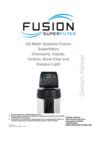
  • 1. US Water Systems Fusion Superfilters Chemsorb, Calcite, Carbon, Bone Char and Katalox-Light REVISION # 1.2 REVISION DATE October 23, 2014 1. Read all instructions carefully before operation. 2. Avoid pinched o-rings during installation by applying (provided with install kit) NSF certified lubricant to all seals. 3. This system is not intended for treating water that is microbiologically unsafe or of unknown quality without adequate disinfection before or after the system. US Water Systems 1209 Country Club Road Indianapolis, IN 46234 1-800-608-8792 WWW.USWATERSYSTEMS.COM Owners Manual
  • 2. 2 Safety Guide  Check and comply with your provincial / state and local codes. You must follow these guidelines.  Use care when handling the filter tank. Do not turn upside down, drop, drag or set on sharp protrusions.  The system works on 12 volt-60 Hz electri- cal power only. Be sure to use only the in- cluded transformer.  Transformer must be plugged into an in- door 120 volt, grounded outlet only.  WARNING: This system is not intend- ed for treating water that is microbiologi- cally unsafe or of unknown quality without adequate disinfection before or after the system. For your safety, the information in this manual must be followed to minimize the risk of elec- tric shock, property damage or personal injury. Be sure to check the entire unit for any shipping damage or missing parts. Also note damage to the shipping cartons. Contact US Water Systems at 1-800-608-8792 for all damage and loss claims. A damage claim must be made within 24 hours of receipt of the unit or the claim may not be honored. Small parts, needed to install the softener, are in a parts bag. To avoid loss of the small parts, keep them in the parts bag until you are ready to use them. Unpacking / Inspection PAGE Unpacking / Inspection 2 Safety Guide 2 Proper Installation 3 Specification 4 Before Starting Installation 6 Sizing Requirements 6 Filter Preparation 8 Installation Instructions 11 System Start Up 15 Programming Instructions 16 About The System 17 Maintenance 18 Main Repair Parts 19 Trouble Shooting 26 Pressure Gauge Installation Drawing 27 Warranty 28 Table of Contents
  • 3. 3 Proper Installation This water filter system must be properly installed and located in accordance with the Installation Instructions before it is used.  Do not install or store where it will not be exposed to temperatures below freezing or exposed to any type of weather. Water freezing in the system will break it. Do not attempt to treat water over 100°F.  Do not install in direct sunlight. Excessive sun or heat may cause distortion or other damage to non-metallic parts.  Properly ground to conform with all gov- erning codes and ordinances.  Use only lead-free solder and flux for all sweat-solder connections, as required by state and federal codes.  Maximum allowable inlet water pressure is 125 psi. If daytime pressure is over 80 psi, night time pressure may exceed the maxi- mum. Use a pressure reducing valve to reduce the flow if necessary.  WARNING: Discard all unused parts and packaging material after installation. Small parts remaining after the installation could be a choke hazard. Overall System Inlet-Outlet Connection Height C Tank B A Model Tank Size A B C FSF-150 10” X 54” 60.25” 57.25” 10” FSF-200 12” X 52” 58.25” 55.25” 12” FSF-250 13” X 54” 60.25” 57.25” 13” FSF-300 14” x 65” 72.25” 68.25” 14” FSF-400 16” x 65” 72.25” 68.25” 16” FSF-500 18” x 65” 72.25” 68.25” 16”
  • 5. 5 Specifications  Continuous operation at flow rates greater than the ser- vice flow rate may affect capacity and efficiency perfor- mance.  The manufacturer reserves the right to make product improvements which may deviate from the specifications and descriptions stated herein, without obligation to change previously manufactured products or to note the change.  Peak flow rates are intended for intermittent use only and are for residential application only  At the stated service flow rates, the pressure drop through these devices will not exceed 15 psig
  • 6. 6 Before Starting Installation Tools, Pipe, and Fittings, Other Materials  Pliers  Screwdriver  Teflon tape  Razor knife  Two adjustable wrenches  Additional tools may be required if modifi- cation to home plumbing is required.  Plastic inlet and outlet fittings are included with the filter. To maintain full valve flow, 3/4” or 1” pipes to and from the filter fittings are recommended. It is important to main- tain the same, or larger, pipe size as the water supply pipe, up to the softener inlet and outlet.  Use copper, brass, or PEX pipe and fit- tings.  Some codes may also allow PVC plastic pipe.  ALWAYS install the included bypass valve, or 3 shut-off valves. Bypass valves let you turn off water to the filter for repairs if needed, but still have water in the house pipes.  5/8” OD drain line is needed for the valve drain. Sizing Requirements Water Pressure The water system must have a pump large enough to deliver the recommended backwash rate with a minimum pressure at the inlet of the filter of 30 psi. If the existing system cannot do this, it must be upgraded to do so. Whenever possible, the water system should be ad- justed to deliver at least 30 psi for even more satisfactory results. Backwash Flow Rates The most important criteria in sizing a filter is the capacity of the pump. The water must pass through the filter media at the proper service flow rate. The filter must also be backwashed at a flow rate sufficient to dislodge and remove the captured particles. Failure to provide sufficient water will cause a build-up of particles in the filter media, impairing its ability. In order for your filter to backwash and rinse properly, your pump must be capable of providing the backwash flow rates indicated on page 4 & 5.
  • 7. 7  Place the filter tank as close as possible to the pressure tank (well system) or water meter (city water).  Place the filter tank as close as possible to a floor drain, or other acceptable drain point (laundry tub, sump, standpipe, etc.).  Connect the filter to the main water supply pipe BEFORE the water heater. DO NOT RUN HOT WATER THROUGH THE FIL- TER. Temperature of water passing through the filter must be less than 100 deg. F.  Do not install the filter in a place where it could freeze. Damage caused by freez- ing is not covered by the warranty.  Put the filter in a place water damage is least likely to occur if a leak develops. The manufacturer will not repair or pay for wa- ter damage.  A 120 volt electric outlet, to plug the includ- ed transformer into, is needed within 6 feet of the filter. The transformer has an at- tached 6 foot power cable. Be sure the electric outlet and transformer are in an inside location, to protect from wet weather.  If installing in an outside location, you must take the steps necessary to assure the fil- ter, installation plumbing, wiring, etc., are as well protected from the elements, con- tamination, vandalism, etc., as when in- stalled indoors.  Keep the filter out of direct sunlight. The sun’s heat may soften and distort plastic parts. Where To Install The Filter
  • 8. 8 Filter Preparation Fusion Backwashing Filter Tank Installation Instructions WATER PRESSURE: A minimum of 20 pounds of water pressure is required for regeneration valve to oper- ate effectively. ELECTRICAL FACILITIES: An uninterrupted alternating current (A/C) supply is required. Note: Other volt- ages are available. Please make sure your voltage supply is compatible with your unit before installation. EXISTING PLUMBING: Condition of existing plumbing should be free from lime and iron buildup. Piping that is built up heavily with lime and/or iron should be replaced. LOCATION OF FUSION NLT TANK AND DRAIN: The Infusion tank should be located close to a drain to prevent air breaks and back flow. CAUTION: Water pressure is not to exceed 80 psi, water temperature is not to exceed 110°F (43°C), and the unit cannot be subjected to freezing conditions. Media Installation 1) Remove the tank from carton. 2) Verify the riser tube is centered in the bottom center of the tank. A flashlight may be necessary. The distributor tube will be flush with the top of the tank when it is cen- tered.
  • 9. 9 Filter Preparation 3) Place a piece of duct tape over the riser tube so no media enters the riser while filling. 4) Use the Blue Funnel provided, to pour the gravel and media into the tank. Pour the grav- el into the tank first, then the media. Pour the gravel and media evenly around the hole to ensure it is well distributed in the tank and pour slow enough, to keep from plugging the hole. A helper may be needed to hold the funnel during the filling process. It is recom- mended that a dust mask and safety goggles be worn to prevent possible injury. A shop vacuum can be used to capture dust during the filling procedure. Pour all the gravel and all the media shipped with the unit into the tank. US Water does not send extra/unused me- dia. 5) When media is installed move tank side to side to settle the media. Remove the funnel and tape from the distributor tube.
  • 10. 10 Filter Preparation 6) Lubricate the distributor O-ring and the tank O-ring on the bottom of the control valve. Then install the upper basket on the bottom of the valve by lining up the tabs then turning the basket clockwise to lock it in place. Place the upper basket over the distributor tube and push the valve on the tank. Thread the valve on the tank by turning it clockwise. Be sure not to cross-thread the valve on the tank. Tighten the valve hand tight, then snug it further by tapping it with the palm of the hand. DO NOT use tools to tighten the valve or damage could occur.
  • 11. 11 Installation Instructions 1. If your hot water tank is electric, turn off the power to it to avoid damage to the element in the tank. 2. If you have a private well, turn the power off to the pump and then shut off the main water shut off valve. If you have municipal water, simply shut off the main valve. Go to the fau- cet, (preferably on the lowest floor of the house) turn on the cold water until all pressure is relieved and the flow of water stops. 3. Locate the filter tank close to a drain where the system will be installed. The surface should be clean and level. 4. Connect the inlet and outlet of the filter using appropriate fittings. Perform all plumbing according to local plumbing codes. Pressure gauges should be added in some applica- tions. There is a drawing on page 27 that shows gauge location.  ON COPPER PLUMBING SYSTEMS BE SURE TO INSTALL A GROUNDING WIRE BETWEEN THE INLET AND OUTLET PIPING TO MAINTAIN GROUNDING WHEN APPLICABLE. Any solder joints being soldered near the valve must be done before connecting any piping to the valve. Always leave at least 6" (152 mm) between the control valve and joints being soldered when soldering pipes that are connected to the valve. Failure to do this could cause damage to the valve. The Fusion Backwashing Filter is equipped with 1” removable connectors. It is recommend- ed that these connectors are installed in the plumbing fitting using Teflon tape then lubricate the o-ring on the connector. Remove the red clips and push the connectors into the bypass valve once they are tight in the plumbing fitting. The red clips can then be re-installed to se- cure the connectors in the bypass valve. The inlet and outlet can be identified on the bypass valve. There are arrows stamped in the bypass valve showing flow (See page 18 diagram). The arrow pointing toward the valve is the inlet and the arrow pointing away from the valve is the outlet. All piping should be secured to prevent stress on the bypass valve and connectors.
  • 12. 12 Hose barb fitting for drain line. Be sure to use a hose clamp to secure the line. 5. Connect the drain hose to the filter valve and secure it with a hose clamp. Run the drain hose to the nearest laundry tub or floor drain. This can be ran overhead or down along the floor. Drain hose should be a minimum of 1/2”. If running the drain line more than 20 ft overhead, it is recommended to increase the hose size to 3/4”. A DIRECT CONNECTION INTO A WASTE DRAIN IS NOT RECOMMENDED. A PHYSICAL AIR GAP OF AT LEAST 1.5” SHOULD BE USED TO AVOID BACTERIA AND WASTEWATER TRAVELING BACK THROUGH THE DRAIN LINE INTO THE FILTER. Be sure to secure the drain line. The softener will drain with force and it should be secured to prevent a leak. Hose clamps should be used to secure the drain line at the connection points. Installation Instructions
  • 13. 13 Installation Instructions 6. Using the Allen Key (included), place the unit in the bypass position (See page 18 for by- pass valve handle placement). Slowly turn on the main water supply. At the nearest cold treated water tap nearby remove the faucet screen, open the faucet and let water run a few minutes or until the system is free of any air or foreign material resulting from the plumbing work. 7. Make sure there are no leaks in the plumbing system before proceeding. Close the water tap when water runs clean. 8. Proceed to start up instructions. Note: The unit is not ready for service until you complete the start-up instructions.
  • 15. 15 System Start-Up 1. Plug the valve into an approved power source. 2. When power is supplied to the control, the screen will display “INITIALIZING WAIT PLEASE” while it finds the service position. 3. Start an Immediate Manual Regeneration. The valve will immediately start moving to the BACKWASH position. 4. Partially open the inlet on the bypass valve slowly and allow water to enter the unit. Allow all air to escape from the unit before turning the water on fully then allow water to run to drain for 3-4 minutes or until all media fines are washed out of the softener indicated by clear water in the drain hose. KATALOX SYSTEMS SHOULD BE BACKWASHED FOR A MINIMUM OF 1 HOUR. IN SOME CASES ADDITIONAL RINSING MAY BE NEEDED. For Katalox filters, when the valve is in the backwash position, unplug the power cord for the valve. This will keep the unit in the backwash cycle. Allow the system to backwash for 1 hour, then plug the power cord back in and go to step 5. All other media types can use the general backwash in Step 4. 5. Press any button to advance to the RINSE position. Slowly open the bypass inlet valve during the rinse cycle until it is fully opened. Check the drain line flow. Allow the water to run for 3-4 minutes or until the water is clear. 6. The valve will automatically advance to the SERVICE position after the RINSE cycle is complete. Open the outlet valve on the bypass, then open the nearest treated water fau- cet and allow the water to run until clear, close the tap and replace the faucet screen. 7. Program time, date, and number of days between regenerations into controller using the following Programming Instructions Start-up Instructions Key Pad Configuration SET- TINGS This function is to enter the basic set up information required at the time of installa- tion. MANUAL REGEN This function is to initiate an immediate or delayed manual regeneration. DOWN / UP Increase or decrease the value of the set- tings while in the programming mode. DELAYED REGENERATION Press and release the MANUAL REGEN. Button to set a delayed regeneration that will occur at the regeneration time. The main dis- play page will show DELAYED REGEN ON. To cancel press and release the MANUAL REGEN. Button. The main display page will show DELAYED REGEN OFF. IMMEDIATE REGENERATION To start an immediate regeneration (or step valve through each position), press and hold the MANUAL REGEN. Button for 3 seconds (until beeps). The valve will start an immedi- ate regeneration. Press any key to skip to the next cycle. Manual Regeneration (Step / Cycle Valve)
  • 16. 16 Backwash Frequency Programming Instructions TIME OF DAY, YEAR, MONTH, DAY, Time of day is for normal operation of system and the scheduling of the re- generation time. The date is used in a diagnostic function to track the last time the system regenerated. REGEN DAYS This value is the number of days between regenerations or back washes to clean the filters. GALLONS Default value is OFF. This should not be changed. REGEN TIME This setting determines the time of day to perform a scheduled regenera- tion. The normal regen time for a filter is 12:00 AM. Settings Press SETINGS key (3 SECONDS / BEEP) VALVE MODE B.W. FILTER TIME OF DAY 12:01 PM YEAR 2012 MONTH AUGUST DAY 21 REGEN DAYS 3 DAYS GALLONS OFF REGEN TIME 12:00 AM PROGRAMMING COMPLETE Contact US Water Systems at 1-800-608-8792 to help with the backwash frequency setting. This can be adjusted by the home owner to suite their individual needs with frequencies available from 1 – 99 days.
  • 17. 17 Control Operation During A Power Failure In the event of a power failure, the valve will keep track of the time and day for 48 hours. The programmed settings are stored in a non-volatile memory and will not be lost during a power failure. If power fails while the unit is in regeneration, the valve will finish regenera- tion from the point it is at once power is restored. If the valve misses a scheduled regenera- tion due to a power failure, it will queue a regeneration at the next regeneration time once power is restored. Main Display About The System Periodically the filter will require a back wash to clean the trapped particles and unpack the filter bed to restore the system flow rates. The table below explains the regeneration steps. Regeneration Process Step Name Description #1 Back Wash Fresh water is introduced to the bottom of the tank flowing upwards expanding the filter media to rinse out any dirt or small particles to the drain and to un- compact the bed to restore full service flow rates. #2 Rinse Fresh water is introduced from the top of the tank flowing down through the filter bed rinsing any unfiltered water to the drain. The main display page will pause on the Date and Time page for 5 seconds. Then it will continually scroll through all of the system diagnostic display pages. Depending on the Valve Type some pages will not be displayed. To manually scroll through the diagnostics, press the down or up key. To reset the TOTAL REGENS, TOTAL GALLONS OVER RUN TOTAL, or PEAK flow rates, press and hold the MENU until the value changes to zero. PARAMETER DESCRIPTION JULY/17/2012 8:30 PM TOTAL 1,500 GAL REMAIN 1,200 GAL LAST REGEN 9/24/12 TOTAL REGENS 10 TOTAL GALLONS 001590 GAL TOTAL 4 DAYS REMAIN 3 DAYS OVER RUN TOTAL 0000 GAL CURRENT 1.5 GPM PEAK 6.5 GPM DELAYED REGEN OFF REGEN TIME 12:00 AM VALVE MODE B.W. FILTER The current setting for regeneration time. The current setting of the valve mode. The total number of regenerations. The total amount of gallons treated by the system. The total amount of water that has exceeded the system capacity over the last 4 regenerations. When remaining goes to zero, the gallons used will be added to over run total. The current flow rate and the peak flow rate since the last regeneration. Advises whether a delayed regeneration has been scheduled manually or automatically. Month, Day, Year, Time The number of days remaining before regeneration. This option is only in filter mode. The total amount is the system capacity when fully regenerated. The remaining is the capacity left in the system. The date of the last regeneration.
  • 18. 18 Automatic Raw Water Bypass During Regeneration The regeneration cycle can last 30 minutes after which filtered water service will be restored. During regeneration, un-filtered water is automatically bypassed for use in the household. Hot water should be used as little as possible during this time to prevent un-filtered water from filling the water heater. This is why automatic regeneration is set for sometime during the night and manual regenerations should be performed when little or no water will be used in the household. Normal regeneration time is 2:00 AM. New Sounds You may notice new sounds as your filter operates. The regeneration cycle lasts up to 30 minutes. During this time, you may hear water running intermittently to the drain. Manual Bypass In the case of emergency you can isolate your water filter from the water supply using the bypass valve located at the back of the control. In normal operation the bypass is open with the on/off knobs in line with the inlet and outlet pipes. To isolate the filter, simply rotate the knobs clockwise (as indicated by the word BYPASS and arrow) until they lock. You can use your water related fixtures and appliances as the wa- ter supply is bypassing the filter. However, the water you use will be hard. To resume water service, open bypass valve by rotating the knobs counterclockwise. Maintenance Maintenance of your new water filter requires very little time or effort but it is essential. Reg- ular maintenance will ensure many years of efficient and trouble-free operation. 1. Periodically make sure your pump is performing satisfactorily to ensure sufficient water is available for backwashing the filter. 2. Periodically test your raw and filtered water to ensure conditions are still the same for your original settings and that the unit is working they way it is intended to. Water testing is often the best way to determine when the filter media will require replacement. 3. Periodically check that the drain line is clear and free from any obstructions.
  • 19. 19 Main Repair Parts Replacement Part Number Part Description DWG # Quantity 60010052 POWER TRANSFORMER 120V-12V A 1 60010002 BYPASS / METER B 1 10010063 485 UP DOWN FLOW FILTER VALVE C 1 60010048 TOP CONE D 1 25020041 844 TANK (75) E 1 25020042 948 TANK (100) E 1 25020043 1054 TANK (150) E 1 25010058 1252 TANK (200) E 1 25030007 1465 TANK (300) E 1 50010005 DISTRIBUTOR 1X54 F 1 REPLACEMENT PARTS - FILTER Replacing Drain Line Flow Control (DLFC) 1. Remove the red clip that secures the drain line elbow. 2. Remove the BLFC washer from the elbow fitting. 3. Reassemble using the reverse procedure.
  • 21. 21 A A A B D F E A C Replacement Part Number Part Description DWG # Quantity 60010020 3/4" NPT ELBOW A 2 60010019 1" NPT STRAIGHT A 2 60010023 3/4" NPT STRAIGHT A 2 60010079 VALVE COUPLING INLET B 1 60010101 VALVE COUPLING OUTLET (METER SIDE) C 1 60010025 PLASTIC SECURE CLIP D 2 60010046 BYPASS SS CLIP E 2 60010047 BYPASS SS SCREW F 2 REPLACEMENT PARTS - CONNECTORS Main Repair Parts - Connectors
  • 22. 22 VALVE REPAIR PARTS LIST Replacement Part Number Part Description Replacement Part Number Part Description 60010127 INJECTOR SET #0000 BLACK 60010129 85HE UPFLOW PISTON ASSEMBLY 60010126 INJECTTOR SET #000 GREY 60010171 85HE DOWNFLOW PISTON ASSEMBLY 60010035 INJECTOR SET #00 VIOLET 60010130 85HE SEAL & SPACER KIT 60010034 INJECTOR SET #0 RED 60010131 85HE DLFC #1 1.5 GPM 60010033 INJECTOR SET #1 WHITE 60010132 85HE DLFC #2 2.0 GPM 60010032 INJECTOR SET #2 BLUE 60010133 85HE DLFC #3 2.4 GPM 60010031 INJECTOR SET #3 YELLOW 60010135 85HE DLFC #5 3.5 GPM 60010128 BLFC 0.2 GPM 60010136 85HE DLFC #A 5.0 GPM 60010110 BLFC 0.3 GPM 60010137 85HE DLFC #B 7.0 GPM 60010082 BLFC 0.7 GPM 60010138 85HE DLFC #C 10.0 GPM Control Valve Exploded View
  • 23. 23 485HE CONTROL VALVE (DOWNFLOW) Replacement Part Number MFG Part Number Part Description DWG # Quantity 5056087 Screw-M5x12(Hexagon) A01 3 5056088 Screw-M5x16(Hexagon With Washer) A02 2 5056047 End Plug Retainer A03 1 5031016 BNT85HE Piston Rod A04 1 5056097 Piston Pin A05 1 5031015 BNT85HE Quad Ring Plug Cover A06 1 5056070 Quad Ring A07 2 5031011 BNT85HE End Plug A08 1 5031014 BNT85HE Piston Retainer A09 1 5057001 BNT85HE Piston(Electrical Downflow) A10 1 5056073 Seal A11 5 5056021 Spacer A12 4 5010082 Drain Fitting-B A13 1 5031005 BNT85HE Spacer A14 1 5056186 DLFC-2# A15 1 5056172 Secure Clip-s A16 2 5031002 BNT85HE Valve Body A17 1 5056508 Screw-M5x12(Hexagon With Washer) A18 5 5030004 BNT85 End Cover A19 1 5030013 O-Ring-¢30×2.65 A20 1 5056063 O-Ring-¢78.74×5.33 A21 1 26010103 O-Ring-¢25×3.55 A22 1 7060007 Valve Bottom Connector A23 1 13000426 Screw-ST2.9X13(Large Washer) A24 2 5031022 O-Ring-¢32×3 A25 1 5031021 O-Ring-¢18×3 A26 1 5031013 Injector Plug Body A27 1 30110007 Plastic Ball ¢6 A28 1 30040089 Injector Throat A29 2 5031012 BNT85HE Injector Fixed Sleeve A30 1 30040090 Injector Nozzle A31 2 5056103 Injector Screen A32 1 5031003 BNT85HE Injector Cover Body A33 1 5031018 O-Ring-¢40×2.65 A34 1 5031004 BNT85HE Injector Cover Cap A35 1 5031027 Screw-M5x25(Hexagon With Washer) A36 4 5056075 Seal Mat A37 1 5056134 O-Ring-¢12×2 A38 3 5056054 Injector Stem A39 1 5056031 Injector Spacer A40 1 5056081 O-Ring-¢12.5×1.8 A41 1 5056030 Injector Cap A42 1 5056093 Injector Screen A43 1 5010049 Special Washer A44 1 5056105 Retaining Ring A45 1 5031010 BNT85HE BLFC Fixed Sleeve A46 2 5056076 BLFC-2# A47 1 5005629 Injector Fitting(3/8".Elbow) A48 1 Control Valve Parts List
  • 25. 25 485HE POWER HEAD (DOWNFLOW) Replacement Part Number MFG Part Number Part Description DWG # Quantity 5056084 Screw-ST3.5X13 B01 10 5010037 Screw-ST2.9X10 B02 9 13000416 Screw-ST3.5X25 B03 1 5031007 BNT85HE Piston Rod Guide Plate B04 1 5056510 Motor-12v/2rpm B05 1 5030014 Motor Power Cable 1 11700005 Wire Connector 2 5056098 Motor Pin B06 1 5031006 BNT85HE Mounting Plate B07 1 5030009 BNT85 Drive Gear B08 1 13000426 Screw-ST2.9X13(Large Washer) A24 2 5056139 Washer-3x13 B09 1 5030007 BNT85 Main Gear B10 1 5030005 BNT185 Housing B11 1 5031017 BNT85HE Brine Gear(Downflow) B12 1 5010023 Magnet(3×2.7) B13 1 5056141 Washer-4x12 B14 1 5056166 Screw-ST4.2X12(Large Washer) B15 1 5031016 BNT85HE Piston Rod A04 1 5010036 Screw-ST3.5X16 B16 1 5031026 BNT85HE Main Pcb(Downflow) B17 1 5010031 Meter Assembly 1 5010046 Meter Strain Rlief 1 5010029 Power Cable 1 5010035 Power Strain Rlief 1 19010105 Wire Rope-3×100 2 5031024 BNT85HE Display(Downflow) B18 1 5030021 BNT85 Wiring Harness 1 5030003 BNT85 Cover B19 1 Power Head Parts List
  • 26. 26 Trouble Shooting Issue Possible Cause Possible Solution 1. No power supply. Check electrical service, fuse, etc. 2. Defective circuit board. Replace faulty parts. 3. Power failure. Reset time of day. 1. By-pass valve open. Close by-pass valve. 2. Electrical service to unit has been interrupted Assure permanent electrical service (check fuse, plug or switch) 3. Defective or stripped media bed Replace media 4. Quality of water has worsened Have water sample analyzed to determine any change 5. Filter capacity too small Replace with larger unit or add another filter 6. Filter not backwashing enough Be sure control is not clogged or drain line restricted. Be sure water pressure has not dropped and that pump has sufficient capacity. 7. Leak between valve and central tube. Check if central tube is cracked or o-ring is damaged. Replace faulty parts. 8. Internal valve leak. Replace valve seals, spacer, and piston assembly. 1. Iron or scale build up in line feeding unit. Clean pipes. 2. Iron build up inside valve or tank. Clean control and add resin cleaner to clean bed. Increase regeneration frequency. 3. Inlet of control plugged due to foreign material. Remove piston and clean control valve. 1. Air in water system. Check well system for proper air eliminator control. 2. Incorrect drain line flow control (DLFC) button. Check for proper flow rate. E. Valve continuously cycles. 1. Defective position sensor PCB. Replace faulty parts. 1. Valve settings incorrect. Check valve settings. 2. Foreign material in control valve. Clean control. 3. Internal leak. Replace seals, spacers, and piston assembly. F. Flow to drain continuously. A. Unit fails to initiate a regeneration cycle. B. FILTER BLEEDS TASTE AND ODOR OR SEDIMENT C. Low water pressure. D. Filter media in drain line.
  • 28. 28 For the lifetime of the original purchaser, at the original residential place of installation of this Fusion Katalox Light Superfilter Water Conditioning System, US WATER SYSTEMS, INC. warrants the following: LIFETIME COVERAGE Media Tanks Free of all costs to you except transportation and labor charges, we warrant that we will replace or repair the fiberglass media tank, if for any reason it is found to be defective, because of faulty materials or workmanship. SEVEN YEAR COVERAGE Valve Assembly & Electronics We warrant that for seven (7) years from the date of purchase, we will replace the valve assemblies or electronic components at no charge to you except for transportation and standard labor charges. Electronics damaged due to environmental issues or improper installation are not covered. GENERAL PROVISIONS This warranty does not apply to any commercial or industrial installations or to any part of the water conditioner which has been subjected to misuse, neglect, alteration or accident; or to any damage caused by fire, flood, freezing, Acts of God, or any other casualty, or if the original serial numbers have been removed. These warranties are in lieu of all other warranties expressed. or implied, and we do not authorize any person to assume for us any other obligation on the sale of this water conditioner. No responsibility is assumed for delays or failure to meet these warranties caused by strike, government regulations or other circumstances beyond the control of US WATER SYSTEMS, INC.. TO OBTAIN WARRANTY SERVICE, CALL OR WRITE: US WATER SYSTEMS, INC. 1209 COUNTRY CLUB ROAD INDIANAPOLIS, IN 46234 (800) 608-USWA. ANY IMPLIED WARRANTIES OF FITNESS OR MERCHANTABILITY ARE LIMITED TO THE TERMS OF THIS EXPRESSED WARRANTY AND THERE ARE NO WARRANTIES WHICH EXTEND BEYOND THOSE HEREIN. US WATER SHALL NOT BE LIABLE FOR ANY INCIDENTIAL OR CONSEQUENTIAL DAMAGES. SOME STATES DO NOT ALLOW THE EXCLUSION OR LIMITATIONS OF INCIDENTAL OR CONSEQUENTIAL DAMAGES SO THE ABOVE LIMITATION MAY NOT APPLY TO YOU. THIS WARRANTY GIVES YOU SPECIFIC LEGAL RIGHTS, AND YOU MAY ALSO HAVE OTHER RIGHTS WHICH VARY FROM STATE TO STATE. THIS WARRANTY MAY BE TRANSFRRED TO A SUBSEQUENT OWNER WITH WRITTEN APPROVAL OF US WATER AND PAYMENT OF STANDARD TRANSFER FEE. Limited Lifetime Warranty