SlideShare ist ein Scribd-Unternehmen logo
1 von 25
Downloaden Sie, um offline zu lesen
Modeling FIFO Communication Channels
Using SystemVerilog Interfaces
Master

FIFO Channel

data

Slave
data

Stuart Sutherland
Sutherland HDL, Inc.
Portland, Oregon, USA
stuart@sutherland-hdl.com

1

1-2

Objectives

Introduce SystemVerilog
Concepts of Communication Channels
Tutorial on SystemVerilog Interfaces
Modeling a FIFO Interface Channel Using Mailboxes
Modeling a FIFO Interface Channel Using Queues
Modeling a Synthesizable FIFO Interface Channel
Conclusions

Modeling FIFO Communication Channels Using SystemVerilog Interfaces
by Stuart Sutherland, Sutherland HDL, Inc.
SNUG-Boston 2004
1
1-3

What is SystemVerilog?
SystemVerilog extends of the IEEE 1364 Verilog standard
New design modeling capabilities
Abstract C language data types
More accurate RTL coding
Interfaces for communication
New verification capabilities
Assertions
Race-free testbenches
Object-oriented test programs

SystemVerilog is the next generation of the Verilog standard
Gives Verilog a much higher level of modeling abstraction
Gives Verilog new capabilities for design verification

Mile High View of
SystemVerilog
3.1a

from C / C++

mailboxes
semaphores
constrained random values
direct C function calls

classes
inheritance
strings

dynamic arrays
associative arrays
references

3.0

SystemVerilog
assertions
test program blocks
clocking domains
process control
interfaces
nested hierarchy
unrestricted ports
automatic port connect
enhanced literals
time values and units
specialized procedures

packages
2-state modeling
packed arrays
array assignments
queues
unique/priority case/if
compilation unit space

int
shortint
longint
byte
shortreal
void
alias

globals
enum
typedef
structures
unions
casting
const

break
continue
return
do–while
++ -- += -= *= /=
>>= <<= >>>= <<<=
&= |= ^= %=

Verilog-2001
ANSI C style ports
generate
localparam
constant functions

standard file I/O
$value$plusargs
`ifndef `elsif `line
@*

(* attributes *)
configurations
memory part selects
variable part select

multi dimensional arrays
signed types
automatic
** (power operator)

Verilog-1995
modules
parameters
function/tasks
always @
assign

$finish $fopen $fclose
$display $write
$monitor
`define `ifdef `else
`include `timescale

initial
disable
events
wait # @
fork–join

wire reg
integer real
time
packed arrays
2D memory

begin–end
while
for forever
if–else
repeat

+ = * /
%
>> <<

Modeling FIFO Communication Channels Using SystemVerilog Interfaces
by Stuart Sutherland, Sutherland HDL, Inc.
SNUG-Boston 2004
2
1-5

Verilog, SystemVerilog
and SystemC
Each hardware design language has unique capabilities

This paper is not about what language is best
This paper is on how SystemVerilog enables modeling intermodule communication at a higher level of abstraction
SystemC
This chart shows...
Software and embedding programming
SystemVerilog does
not replace SystemC
SystemVerilog bridges
a gap between Verilog
and SystemC

Verilog
with
SystemVerilog

Object Oriented programming
Behavioral and
transaction modeling

VHDL
Verilog

RTL modeling

Gate-level modeling

Chart reflects the author’s perception
of general language overlap

Switch-level modeling

1-6

What’s Next

Introduce SystemVerilog
Concepts of Communication Channels
Tutorial on SystemVerilog Interfaces
Modeling a FIFO Interface Channel Using Mailboxes
Modeling a FIFO Interface Channel Using Queues
Modeling a Synthesizable FIFO Interface Channel
Conclusions

Modeling FIFO Communication Channels Using SystemVerilog Interfaces
by Stuart Sutherland, Sutherland HDL, Inc.
SNUG-Boston 2004
3
1-7

Inter-Module Communication
Verilog connects models using detailed module ports
Each discrete signal must be declared as a port

SystemC provides communication channels
Encapsulate how information is transferred between modules
Allow abstract, high-level communication

SystemVerilog has communication interfaces
Encapsulate how information is transferred between modules
A new paradigm for inter-module communication
Can SystemVerilog interfaces provide the same abstract
communication capabilities as SystemC channels?
Can SystemVerilog interfaces be synthesized?

1-8

SystemC Channels
SystemC provides channels and interfaces
A “channel” encapsulates how information is transferred between
blocks of a design
An “interface” defines a set of methods (functions) to send and
receive data through the channel

There are two types of channels
Built-in channels that are pre-defined in SystemC
Includes FIFO, Mutex, and Semaphore channels
Represent abstract communication
Generally not synthesizable
User-defined channels
Can be modeled as abstract or at a more detailed level
Can be synthesizable
Modeling FIFO Communication Channels Using SystemVerilog Interfaces
by Stuart Sutherland, Sutherland HDL, Inc.
SNUG-Boston 2004
4
1-9

A SystemC FIFO Channel
FIFOs are typically used to communicate between design
blocks that operate on different, asynchronous clocks
The SystemC built-in FIFO channel:
Is unsized — any amount of data can be in the channel
Is untyped — any data type can be sent through the channel
Provides write/read methods to send data through the channel
Methods are built-in — end user does not see how they work
MASTER
module

read
method

packet
data packet

...

write pointer

write
method

SLAVE
module

data packet
data packet

read pointer

packet

1-10

What’s Next

Introduce SystemVerilog
Concepts of Communication Channels
Tutorial on SystemVerilog Interfaces
Modeling a FIFO Interface Channel Using Mailboxes
Modeling a FIFO Interface Channel Using Queues
Modeling a Synthesizable FIFO Interface Channel
Conclusions

Modeling FIFO Communication Channels Using SystemVerilog Interfaces
by Stuart Sutherland, Sutherland HDL, Inc.
SNUG-Boston 2004
5
1-11

Inter-Module Communication:
Verilog Style

module MASTER (input
clock,
inout [31:0] data,
output [15:0] address,
output
request,
input
grant,
are in the module
input
ready );

Verilog connects modules at
Connection details
the implementation level
MASTER
module

SLAVE
module

data

...

address

module SLAVE

request
grant

Connection details
are duplicated in
other modules

ready
clock

(input
clock,
inout [31:0] data,
input [15:0] address,
input
request,
output
grant,
output
ready );

...

I want to be an engineer,
not a typist!

module top (input clock);
wire [31:0] data,
wire [15:0] address,
Netlists must duplicate wire
request, grant, ready;

the connection detail
(yet again)

MASTER i1 (clock, data, address,
request, grant, ready);
SLAVE i2 (clock, data, address,
request, grant, ready);
endmodule

1-12

Inter-Module Communication:
SystemVerilog Style
Interfaces encapsulate
inter-module communication
MASTER
module

BUS
data
address
request
grant

SLAVE
module

ready
clock

Now I can concentrate on
designing instead of typing!

Connection details
interface BUS;
are in the interface
wire [31:0] data;
logic [15:0] address;
logic
request, grant, ready;
endinterface
module MASTER (interface io_bus);
...
endmodule
module SLAVE (interface io_bus);
...
Modules and netlist do not
endmodule

duplicate the connection details

module top (input clock);
instantiate the interface
BUS
io ();
(io is the instance name)
MASTER i1 (io, clock);
SLAVE i2 (io, clock);
endmodule
connect interface instance
to module port

Modeling FIFO Communication Channels Using SystemVerilog Interfaces
by Stuart Sutherland, Sutherland HDL, Inc.
SNUG-Boston 2004
6
1-13

Interface Modports
The module’s port direction definitions are moved to within the
interface, using the modport keyword (for “module’s ports”)
Encapsulates port lists that used to be scattered in many modules
MASTER
module

BUS
data
address
request
grant
ready

interface BUS ;
wire
[31:0] data;
logic [15:0] address;
logic
request, grant, ready;

SLAVE
module

modport master_ports (inout
output
output
input
input

data,
address,
request,
grant,
ready );

modport slave_ports

data,
address,
request,
grant,
ready );

A modport defines the
port directions from the
module’s point of view

clock

(inout
input
input
output
output

endinterface

Selecting Which Modport
Definition To Use

1-14

SystemVerilog has two ways to select which modport to use
At the module instance — allows “generic module ports”
interface BUS;
modport master_ports (...)
modport slave_ports (...)
endinterface

Each instance of the module can
be connected to a different
interface or a different modport

module MASTER (interface io_bus);
...
endmodule
connect to interface using
module top (input clock); the master_ports port list
BUS
io ();
MASTER i1 (io.master_ports, clock);
...

endmodule

At the module instance — prevents incorrect corrections
interface BUS;
modport master_ports (...)
modport slave_ports (...)
endinterface

Hard coded interface port means
each instance of the module will
be connected the same way

module SLAVE (BUS.slave_ports io_bus);
...
connect to interface using
endmodule
the slave_ports port list
module top (input clock);
BUS
io ();
...

SLAVE i2 (io, clock);
endmodule

Modeling FIFO Communication Channels Using SystemVerilog Interfaces
by Stuart Sutherland, Sutherland HDL, Inc.
SNUG-Boston 2004
7
1-15

Interface Methods
Interfaces can contain “methods”
Defined using Verilog/SystemVerilog tasks and functions
Used to encapsulate inter-module communication functionality
interface BUS;
...
task Read (...);

Methods encapsulate communication functionality into one
place, instead of being fragmented across multiple modules

...

endtask
task Write (...);

communication methods

...

endtask
function bit ParityGen (...);
...

endfunction

modules can import interface
methods through modports

modport master_ports (import Read, Write,
input ... );
modport slave_ports

(import Read, Write, ParityGen,
input ... );

endinterface

Referencing Signals and
Methods In An Interface

1-16

Modules can reference signals and methods within the
interface using a hierarchical path name
<interface_port_name>.<signal_or_method_name>
interface port name
module MASTER (interface io_bus); // interface port
...
always @(posedge clock) begin
if (io_bus.request)
reference signal in interface
io_bus.Read(...);
...
end
reference method in interface
...
endmodule

Synthesis supports this special case of using hierarchical path names

Modeling FIFO Communication Channels Using SystemVerilog Interfaces
by Stuart Sutherland, Sutherland HDL, Inc.
SNUG-Boston 2004
8
1-17

Interface Processes
An interface can contain procedural code and
continuous assignments
initial, always, always_ff, always_comb, always_latch, assign
Processes encapsulate communication functionality
that might otherwise be spread across several modules
interface fifo_channel ;
...
// calculate fifo_empty flag
always_ff @(posedge read_clock, negedge read_resetN) begin
if (!read_resetN) fifo_empty <= 0;
else
fifo_empty <= (rd_ptr_next == rd_ptr_synced);
end
...
endinterface

1-18

Parameterized Interfaces
Interfaces can be parameterized, the same as Verilog modules
Allows each instance of an interface to be reconfigured
interface fifo_channel #(parameter FifoSize = 8, PtrSize = 4,
parameter type DataType = int );
...
DataType write_data;
SystemVerilog also allows
DataType read_data;
data types to be parameterized
...
endinterface

module top_level (input clock, resetN);
...
fifo_channel #(.DataType(real)) FIFO ();
...
interface instance is reconfigured
endmodule

to use a different data type

Modeling FIFO Communication Channels Using SystemVerilog Interfaces
by Stuart Sutherland, Sutherland HDL, Inc.
SNUG-Boston 2004
9
1-19

The FIFO Example Data Types
The FIFO examples used in this paper transport packets for an
ATM Switch

CLP

...

NNI Cell

GFC VPI11-4
VPI3-0
VCI15-12
VCI11-4
VCI3-0
PT
HEC
Payload 0
Payload 47

CLP

...

UNI Cell

GFC
VPI7-4
VPI3-0
VCI15-12
VCI11-4
VCI3-0
PT
HEC
Payload 0

typedef struct { // UNI Cell
bit
[ 3:0] GFC;
bit
[ 7:0] VPI;
SystemVerilog adds
bit
[15:0] VCI;
structures and userbit
CLP;
defined types to Verilog
bit
[ 2:0] T;
bit
[ 7:0] HEC;
bit [0:47] [ 7:0] Payload;
} uniType;

typedef struct { // NNI Cell
bit
[11:0] VPI;
bit
[15:0] VCI;
bit
CLP;
bit
[ 2:0] PT;
bit
[ 7:0] HEC;
bit [0:47] [ 7:0] Payload;
} nniType;

Payload 47

1-20

What’s Next

Introduce SystemVerilog
Concepts of Communication Channels
Tutorial on SystemVerilog Interfaces
Modeling a FIFO Interface Channel Using Mailboxes
Modeling a FIFO Interface Channel Using Queues
Modeling a Synthesizable FIFO Interface Channel
Conclusions

Modeling FIFO Communication Channels Using SystemVerilog Interfaces
by Stuart Sutherland, Sutherland HDL, Inc.
SNUG-Boston 2004
10
1-21

FIFO Channel Example 1: An
Abstract Version

The first FIFO interface example in this paper is modeled at a
high level of abstraction
Closely approximates a SystemC FIFO built-in channel
Requires very few lines of code to model
The FIFO storage is modeled using SystemVerilog mailboxes
MASTER
module

packet
write pointer

write
method

read
method

...

data packet

SLAVE
module

data packet
data packet

read pointer

packet

built-in mailbox methods will be used for writing and reading the FIFO

1-22

Mailboxes
A mailbox is a communication mechanism where data can be
sent to a mailbox by one process and retrieved by another
SystemVerilog mailboxes behave like real mailboxes
When a letter is delivered to a mailbox, the letter can be retrieved
If the post has not yet been delivered, a process can:
Choose to wait for post delivery, or
Come back later and check again

Mailboxes can be either bounded or unbounded
A bounded mailbox is full when it contains a maximum number of
messages
A process attempting to place a message into a full mailbox
must wait until there is room available in the mailbox queue
Unbounded mailboxes never suspend send operations
Modeling FIFO Communication Channels Using SystemVerilog Interfaces
by Stuart Sutherland, Sutherland HDL, Inc.
SNUG-Boston 2004
11
Overview of
SystemVerilog Mailboxes

1-23

SystemVerilog has a predefined object-oriented mailbox class
A communication mechanism whereby
Messages can be placed in a mailbox
by one process...

...and retrieved by another process

If there are no messages in the mailbox, the retrieving process can:
Suspend and wait for a message (block)
Come back later and check again

1-24

Mailbox Capacity
A mailbox is a built-in class object
A new mailbox is “constructed” using a new function
construct a mailbox called “FIFO_1”

mailbox FIFO_1 = new;

The mailbox size can be unbounded or bounded
An unbounded mailbox is never full
A bounded mailbox has a max number of messages it can hold
A process attempting to place a message into a full mailbox
must wait until there is room available in the mailbox
The size of the mailbox is passed as an argument to new
construct a bounded mailbox

mailbox FIFO_2 = new(8);

SystemC built-in FIFOs are unbounded, but the example in this
paper uses a bounded mailbox, which is more like hardware

Modeling FIFO Communication Channels Using SystemVerilog Interfaces
by Stuart Sutherland, Sutherland HDL, Inc.
SNUG-Boston 2004
12
1-25

Mailbox Message Type
A mailbox can be typeless or typed
A typeless mailbox can transfer any data type
The user must ensure that data is retrieved as the same data
type in which it was stored
Run-time errors occur if try to retrieve the wrong type
A typed mailbox can only transfer data of a specific type
Sending or retrieving the wrong type is a compile-time error
The mailbox type is defined using parameter redefinition
construct a typed mailbox

mailbox #(int) FIFO_3 = new(8);

SystemC built-in FIFOs are typeless, but the example in this
paper uses a typed mailbox, which is more like hardware

1-26

Blocking Mailbox Methods
SystemVerilog mailboxes have several built-in methods
put(message) — places a message in a mailbox

If the mailbox is full, the process is suspended (blocked) until
there is room in the mailbox to place the message
get(variable) — retrieves a message from a mailbox
If the mailbox is empty, the process is suspended (blocked)
until a message is placed in the mailbox
mailbox #(int) FIFO = new(8);
int data_in;
always @(posedge write_clock) begin
if (data_ready) FIFO.put(data_in);
end
int data_out;
always @(posedge read_clock) begin
FIFO.get(data_out);
A run-time error occurs if the data type passed to
end

get() does not match the data type in the mailbox

Modeling FIFO Communication Channels Using SystemVerilog Interfaces
by Stuart Sutherland, Sutherland HDL, Inc.
SNUG-Boston 2004
13
1-27

Nonblocking
Mailbox Methods
Mailboxes can be used without blocking process execution
status = tryput(message) — similar to put(), except that the
process does not suspend if the mailbox is full
Returns 0 if the mailbox is full; the message is not delivered
Returns 1 if the mailbox is not full; the message is delivered
status = tryget(variable) — similar to get(), except that the
process will not suspend if the mailbox is empty
Returns 0 if the mailbox is empty
Returns 1 if the mailbox is not empty and the
message type matches the argument type
Returns -1 if not empty, but the message type
does not match between the argument type
There are additional mailbox methods that are not covered in this presentation

1-28

A FIFO Channel Model Using
Interfaces and Mailboxes
interface fifo_channel_1 #(parameter
FifoSize = 8,
parameter type DataType = uniType);

parameterized
size and type

DataType write_data;
DataType read_data;
bit fifo_empty, fifo_full;
mailbox #(DataType) FIFO = new(FifoSize);

storage is a bounded, typed mailbox

function automatic void Write (input DataType write_data);
void'(FIFO.tryput(write_data));
fifo_full = ~(FIFO.num < FifoSize);
endfunction
function automatic void Read (output DataType read_data);
fifo_empty = (FIFO.num == 0);
void'(FIFO.tryget(read_data) );
endfunction
modport sender (input write_data,
output fifo_full,
import Write);
modport reader (output read_data,
output fifo_empty,
import Read);

write/read methods
are encapsulated
in the interface

module port lists are
encapsulated in the interface

endinterface: fifo_channel_1

Modeling FIFO Communication Channels Using SystemVerilog Interfaces
by Stuart Sutherland, Sutherland HDL, Inc.
SNUG-Boston 2004
14
Connecting and Using the
FIFO Interface Channel

1-29

“processor1” places data into the FIFO channel
module processor1 #(parameter type DataType = uniType)
(fifo_channel_1.sender fifo,
interface port
input clock, write_resetN);
DataType data_packet;
always_ff @(posedge clock)
if (write_enable && !fifo.fifo_full)
call to interface method
fifo.Write(data_packet);
...

“processor2” retrieves data from the FIFO channel
module processor2 #(parameter type DataType = uniType)
(fifo_channel_1.reader fifo,
interface port
input clock, resetN);
DataType data_packet;
always_ff @(posedge clock)
if (read_enable && !fifo.fifo_empty)
call to interface method
fifo.Read(data_packet);
...

a top-level module connects the interface to the modules
module top_level (input clock1, clock2, resetN);
instance of interface
fifo_channel_1 #(.DataType(nniType)) FIFO ();
processor1 #(.DataType(nniType)) p1 (FIFO, clock1, resetN);
processor2 #(.DataType(nniType)) p2 (FIFO, clock2, resetN);
endmodule: top_level
connect the interface

Synthesis Considerations of
the FIFO Mailbox Model

1-30

SystemVerilog mailboxes are not synthesizable
HDL Compiler (front-end to DC) does not currently support
SystemVerilog’s object-oriented programming
Mailboxes do not have the level of detail needed to implement
clock domain crossing FIFO logic
But don’t despair — this abstract model is still valuable!
• Easy and fast to model
• Can be used to verify inter-module communications
• Can be used to verify FIFO size at various clock speeds
The next few pages show another way
to model a FIFO interface channel

Modeling FIFO Communication Channels Using SystemVerilog Interfaces
by Stuart Sutherland, Sutherland HDL, Inc.
SNUG-Boston 2004
15
1-31

What’s Next

Introduce SystemVerilog
Concepts of Communication Channels
Tutorial on SystemVerilog Interfaces
Modeling a FIFO Interface Channel Using Mailboxes
Modeling a FIFO Interface Channel Using Queues
Modeling a Synthesizable FIFO Interface Channel
Conclusions

FIFO Channel Example 2:
Using SystemVerilog Queues

1-32

SystemVerilog adds dynamic queues to Verilog
A dynamic array — can grow and shrink in size during simulation
Can represent FIFO, LIFO or other types of queues

A queue is declared like an array, but using $ for the range
Optionally, a maximum size for the queue can be specified
int q1 [$];

an empty queue, with an unbounded size

int q2 [$] = {1,2,3,5,8};

unbounded queue, initialized with 5 locations

typedef struct {int a, b; bit flag} packet_t;
packet_t q3 [$:16];
a bounded queue, with a maximum size of 16
A queue can only hold one data type, which
is specified when the queue is declared

Modeling FIFO Communication Channels Using SystemVerilog Interfaces
by Stuart Sutherland, Sutherland HDL, Inc.
SNUG-Boston 2004
16
1-33

Queue Methods
SystemVerilog queues have several built-in methods
push_front(<value>) — adds a new location at the beginning of the

queue with the value
push_back(<value>) — adds a new location at the end of the queue

with the value
variable = pop_front() — removes the first element of the queue and

returns its value
variable = pop_back() — removes the last element of the queue and

returns its value
insert(<index>,<value>) — changes the value of a queue location

without changing the queue size
variable = <queue_name>[<index>] — retrieves the value of a queue

location without changing the queue size
variable = size() — returns the current number of elements in the queue
It is a run-time error to write to a full queue or to read from an empty queue

1-34

A FIFO Channel Model Using
Interfaces and Queues
interface fifo_channel_2 #(parameter
FifoSize = 8,
parameter type DataType = uniType);

parameterized
size and type

DataType write_data;
DataType read_data;
bit fifo_empty, fifo_full;
DataType FIFO [$:FifoSize];

storage is a bounded queue

function automatic void Write (input DataType write_data);
FIFO.push_back(write_data);
fifo_full = ~(FIFO.PtrSize < FifoSize);
endfunction
function automatic void Read (output DataType read_data);
read_data = FIFO.pop_front;
fifo_empty = (FIFO.PtrSize == 0);
endfunction
modport sender (input write_data,
output fifo_full,
import Write);
modport reader (output read_data,
output fifo_empty,
import Read);

write/read method
names are the
same as previous
example

modport definitions are the
same as previous example

endinterface: fifo_channel_2

Modeling FIFO Communication Channels Using SystemVerilog Interfaces
by Stuart Sutherland, Sutherland HDL, Inc.
SNUG-Boston 2004
17
Connecting and Using the
FIFO Interface Example 2

1-35

The second FIFO example can be used in the same way as the
first example
The modport definitions are exactly the same
The method names are exactly the same
The method formal arguments are the same
the FIFO mailbox example and the FIFO-queue example
are completely interchangeable
module top_level (input clock1, clock2, resetN);
fifo_channel_1 #(.DataType(nniType)) FIFO ();
instance of interface
fifo_channel_2 #(.DataType(nniType)) FIFO ();
processor1 #(.DataType(nniType)) p1 (FIFO, clock1, resetN);
processor2 #(.DataType(nniType)) p2 (FIFO, clock2, resetN);
endmodule: top_level

1-36

Queues versus Mailboxes
Is there an advantage to modeling the FIFO with
a SystemVerilog queue instead of a mailbox?
Yes! SystemVerilog queues are arrays, instead of
abstract objects, and therefore are synthesizable.

Mailbox advantages for representing a FIFO
Very easy to model
Closely approximates the methods in SystemC FIFO channels
Intuitive to use at a system level or testbench level of design

Queue advantages for representing a FIFO
Easy to model at an abstract level
More closely approximates a hardware FIFO
Can be synthesizable (more about this on the next page)

Modeling FIFO Communication Channels Using SystemVerilog Interfaces
by Stuart Sutherland, Sutherland HDL, Inc.
SNUG-Boston 2004
18
Synthesis Considerations of
the FIFO Queue Model

1-37

The SystemVerilog queue construct is synthesizable, but...
HDL Compiler does not yet support queues (as of July 2004)
The write and read methods are too abstract
Do not contain the information needed to
properly synthesize cross domain
clock synchronization

FIFO synchronization is covered in two SNUG papers from 2002
“Simulation and Synthesis Techniques for Asynchronous FIFO Design”,
by Cliff Cummings
“Simulation and Synthesis Techniques for Asynchronous FIFO Design with
Asynchronous Pointer Comparisons”, by Cliff Cummings and Peter Alfke
These papers can be downloaded from www.sunburst-design.com/papers

1-38

What’s Next

Introduce SystemVerilog
Concepts of Communication Channels
Tutorial on SystemVerilog Interfaces
Modeling a FIFO Interface Channel Using Mailboxes
Modeling a FIFO Interface Channel Using Queues
Modeling a Synthesizable FIFO Interface Channel
Conclusions

Modeling FIFO Communication Channels Using SystemVerilog Interfaces
by Stuart Sutherland, Sutherland HDL, Inc.
SNUG-Boston 2004
19
1-39

Synthesizing Interfaces
The Synthesis process:
Expands an interface port to separate ports (using the modport
port list)
Makes local copies of the imported methods (tasks and functions)
Requires that the methods be declared as automatic
interface BUS ;
bit request, grant;
task automatic Read(...);

RTL module MASTER (BUS.master_ports a,
input clock );
Model
...

...

endtask
modport master_ports
(output request,
input grant,
import Read );
endinterface

endinterface

Synthesized module MASTER (output request,
input grant,
Model
input clock );

...

endinterface

synthesized copy
of the Read task

Modeling a Synthesizable
FIFO Channel

1-40

To be synthesizable, a FIFO model must have:
RTL level clock synchronizers
FIFOs are typically used to transfer data between domains
running on different, asynchronous clocks
Add RTL level full and empty flag generation
Full and empty flags can be affected by different clocks, and
therefore require extra hardware

The advantages of abstract queues can be maintained
The interface still encapsulates the communication details
Modules still communicate by calling write and read methods
Queue methods can be used instead of RTL write pointers and
read pointers (maybe)
It remains to be proven as to how well synthesis will implement queue methods...

Modeling FIFO Communication Channels Using SystemVerilog Interfaces
by Stuart Sutherland, Sutherland HDL, Inc.
SNUG-Boston 2004
20
1-41

Synthesizable FIFO Using
Queues and RTL Code
interface fifo_channel_3 #(parameter
FifoSize = 8,
parameter type DataType = uniType);

parameterized
size and type

DataType write_data;
DataType read_data;
bit fifo_empty, fifo_full;
DataType FIFO [$:FifoSize];

storage is a bounded queue, same as previous example

function automatic void Write (input DataType write_data);
FIFO.push_back(write_data);
endfunction
function automatic void Read (output DataType read_data);
read_data = FIFO.pop_front;
endfunction

write/read methods
only push/pop data
(full and empty flags
are set using RTL
code, on next page)

modport sender (input write_data,
output fifo_full, write_clock, write_enable, write_resetN,
import Write,
// internal signals used within the interface
inout wr_ptr, wr_ptr_synced, wr_ptr_next, wr_cntr,
wr_cntr_next, wr_ptr_2nd_msb, wr_ptr_synced_2nd_msb
);

modport definitions are more detailed than
previous example to support RTL code

modport reader (...);

(example continued on next slide)

Synthesizable FIFO
(continued)
always_ff @(posedge write_clock, negedge write_resetN)
if (!write_resetN) {wr_ptr_synced,wr_ptr} <= 0;
else
{wr_ptr_synced,wr_ptr} <= {wr_ptr,rd_ptr};
always_ff @(posedge read_clock, negedge read_resetN)
if (!read_resetN) {rd_ptr_synced,rd_ptr} <= 0;
else
{rd_ptr_synced,rd_ptr} <= {rd_ptr,wr_ptr};
always_ff @(posedge write_clock, negedge write_resetN)
if (!write_resetN) wr_ptr <= 0;
else
wr_ptr <= wr_ptr_next;
always_comb begin
for (int i=0; i<=PtrSize; i++) wr_cntr[i] = ^(wr_ptr>>i);
if (!fifo_full && write_enable) wr_cntr_next = wr_cntr + 1;
else
wr_cntr_next = wr_cntr;
wr_ptr_next = (wr_cntr_next>>1)^wr_cntr_next;
end

1-42

clock
synchronization

write control

assign wr_ptr_2nd_msb = wr_ptr_next[PtrSize]^wr_ptr_next[PtrSize-1];
assign wr_ptr_synced_2nd_msb = wr_ptr_synced[PtrSize]^wr_ptr_synced[PtrSize-1];
always_ff @(posedge write_clock, negedge write_resetN)
fifo_full logic
if (!write_resetN) fifo_full <= 0;
else fifo_full <= ((wr_ptr_next[PtrSize]
!= wr_ptr_synced[PtrSize]) &&
(wr_ptr_2nd_msb
== wr_ptr_synced_2nd_msb ) &&
(wr_ptr_next[PtrSize-2:0] == wr_ptr_synced[PtrSize-2:0])
);

(example continued on next slide)

Modeling FIFO Communication Channels Using SystemVerilog Interfaces
by Stuart Sutherland, Sutherland HDL, Inc.
SNUG-Boston 2004
21
1-43

Synthesizable FIFO
(continued)
always_ff @(posedge read_clock, negedge read_resetN)
if (!read_resetN) rd_ptr <= 0;
else
rd_ptr <= rd_ptr_next;
always_comb begin
for (int i=0; i<=PtrSize; i++) rd_cntr[i] = ^(rd_ptr>>i);
if (!fifo_empty && read_enable) rd_cntr_next = rd_cntr + 1;
else
rd_cntr_next = rd_cntr;
rd_ptr_next = (rd_cntr_next>>1)^rd_cntr_next;
end
always_ff @(posedge read_clock, negedge read_resetN) begin
if (!read_resetN) fifo_empty <= 0;
else
fifo_empty <= (rd_ptr_next == rd_ptr_synced);
end

read control

fifo_empty
logic

endinterface: fifo_channel_3

1-44

What’s The Point?
If writing a synthesizable RTL FIFO Interface takes so
much code, why not just leave the RTL logic in the modules?

• Interfaces represent inter-module communication
• a FIFO in a module is another design hierarchy block
• Interfaces simplify module connections to the FIFO
• One interface port instead of dozens of ports
• Interfaces encapsulate communication methods
• Inter-connecting modules call interface methods
instead of using discrete signals
• Abstract and RTL interfaces are easily interchangeable

Modeling FIFO Communication Channels Using SystemVerilog Interfaces
by Stuart Sutherland, Sutherland HDL, Inc.
SNUG-Boston 2004
22
1-45

Connecting and Using the
RTL/Queue FIFO Interface

The RTL/queue FIFO interface is almost interchangeable with
the abstract FIFO interfaces
The method names are the same
The method formal arguments are the same
But..., the modport definitions are not the same, because the RTL
needs additional signals, such as clock and reset
module processor1 #(parameter type DataType = uniType)
(fifo_channel_3.sender fifo,
input clock, write_resetN);
DataType data_packet;
always_ff @(posedge fifo.clock)
if (write_enable && !fifo.fifo_full)
fifo.Write(data_packet);
...

Clock and reset are part of
the interface, instead of
separate module ports
The methods and other
FIFO signals are the same
as with the abstract FIFO

Is there a way to make the models completely interchangeable?
Yes, clock and reset could also have been part of the abstract
FIFO models (even if not used inside the interface)

1-46

Synthesis Considerations
Synthesis places some restrictions on interfaces and queues
that should be noted
These restrictions are NOT part
of the SystemVerilog standard!

Interface declaration order

Synthesis must compile the interface and the module using the
interface together, with the interface read in first

Methods must be automatic
Tasks and functions in an interface that are called by modules must
be automatic, so that each module sees a local copy

Internal interface signals must be included in modports
Signals directly and indirectly referenced by a module must be listed
in the module’s modport list

Queues not yet implemented
At the time this paper was written, neither VCS nor HDL Compiler
were supporting SystemVerilog queues
Examples were tested using static arrays as a work around)

Modeling FIFO Communication Channels Using SystemVerilog Interfaces
by Stuart Sutherland, Sutherland HDL, Inc.
SNUG-Boston 2004
23
1-47

What’s Next

Introduce SystemVerilog
Concepts of Communication Channels
Tutorial on SystemVerilog Interfaces
Modeling a FIFO Interface Channel Using Mailboxes
Modeling a FIFO Interface Channel Using Queues
Modeling a Synthesizable FIFO Interface Channel
Conclusions

1-48

Conclusions
Verilog inter-module communication is at a low-level
SystemVerilog adds interfaces to Verilog
High-level inter-module communication
Encapsulates communication details in one place
Eliminates port declaration redundancy

SystemC provides abstract communications channels, such as
FIFOs, mutex, and semaphores
The built-in SystemC channels are not synthesizable

SystemVerilog interfaces can effectively model the behavior of
SystemC channels
Can be simple and abstract, but not synthesizable
Can be more detailed, to be synthesizable

Modeling FIFO Communication Channels Using SystemVerilog Interfaces
by Stuart Sutherland, Sutherland HDL, Inc.
SNUG-Boston 2004
24
1-49

Future Work

Make the three interface examples fully interchangeable
The method names and arguments are already the same
The modports need to be the same

Add assertions to the interface
Assert that no writes are made to a full FIFO
Assert that no reads are made to an empty FIFO

Prove that the mixed RTL/queue example is synthesizable
Waiting for HDL Compiler to implement the queue construct and
queue methods

1-50

Questions?

Modeling FIFO Communication Channels Using SystemVerilog Interfaces
by Stuart Sutherland, Sutherland HDL, Inc.
SNUG-Boston 2004
25

Weitere ähnliche Inhalte

Was ist angesagt?

DOUBLE PRECISION FLOATING POINT CORE IN VERILOG
DOUBLE PRECISION FLOATING POINT CORE IN VERILOGDOUBLE PRECISION FLOATING POINT CORE IN VERILOG
DOUBLE PRECISION FLOATING POINT CORE IN VERILOGIJCI JOURNAL
 
Digital Circuit Verification Hardware Descriptive Language Verilog
Digital Circuit Verification Hardware Descriptive Language VerilogDigital Circuit Verification Hardware Descriptive Language Verilog
Digital Circuit Verification Hardware Descriptive Language VerilogAbhiraj Bohra
 
Lecture 13 intermediate code generation 2.pptx
Lecture 13 intermediate code generation 2.pptxLecture 13 intermediate code generation 2.pptx
Lecture 13 intermediate code generation 2.pptxIffat Anjum
 
Design, Analysis and Implementation of Modified Luby Transform Code
Design, Analysis and Implementation of Modified Luby Transform CodeDesign, Analysis and Implementation of Modified Luby Transform Code
Design, Analysis and Implementation of Modified Luby Transform CodeIOSR Journals
 
Verilog tutorial
Verilog tutorialVerilog tutorial
Verilog tutorialraju reddy
 
Structure of the compiler
Structure of the compilerStructure of the compiler
Structure of the compilerSudhaa Ravi
 
Pattern-based Definition and Generation of Components for a Synchronous React...
Pattern-based Definition and Generation of Components for a Synchronous React...Pattern-based Definition and Generation of Components for a Synchronous React...
Pattern-based Definition and Generation of Components for a Synchronous React...ijeukens
 
System Verilog Tutorial - VHDL
System Verilog Tutorial - VHDLSystem Verilog Tutorial - VHDL
System Verilog Tutorial - VHDLE2MATRIX
 
Verilog Tutorial - Verilog HDL Tutorial with Examples
Verilog Tutorial - Verilog HDL Tutorial with ExamplesVerilog Tutorial - Verilog HDL Tutorial with Examples
Verilog Tutorial - Verilog HDL Tutorial with ExamplesE2MATRIX
 
Test System Architectures using Advanced Standardized Test Languages
Test System Architectures using Advanced Standardized Test LanguagesTest System Architectures using Advanced Standardized Test Languages
Test System Architectures using Advanced Standardized Test LanguagesAxel Rennoch
 
Fpga 07-port-rules-gate-delay-data-flow-carry-look-ahead-adder
Fpga 07-port-rules-gate-delay-data-flow-carry-look-ahead-adderFpga 07-port-rules-gate-delay-data-flow-carry-look-ahead-adder
Fpga 07-port-rules-gate-delay-data-flow-carry-look-ahead-adderMalik Tauqir Hasan
 
Module 3: Introduction to LINQ (Material)
Module 3: Introduction to LINQ (Material)Module 3: Introduction to LINQ (Material)
Module 3: Introduction to LINQ (Material)Mohamed Saleh
 

Was ist angesagt? (20)

DOUBLE PRECISION FLOATING POINT CORE IN VERILOG
DOUBLE PRECISION FLOATING POINT CORE IN VERILOGDOUBLE PRECISION FLOATING POINT CORE IN VERILOG
DOUBLE PRECISION FLOATING POINT CORE IN VERILOG
 
Digital Circuit Verification Hardware Descriptive Language Verilog
Digital Circuit Verification Hardware Descriptive Language VerilogDigital Circuit Verification Hardware Descriptive Language Verilog
Digital Circuit Verification Hardware Descriptive Language Verilog
 
Hdl
HdlHdl
Hdl
 
HDL (hardware description language) presentation
HDL (hardware description language) presentationHDL (hardware description language) presentation
HDL (hardware description language) presentation
 
Chapter 6
Chapter 6Chapter 6
Chapter 6
 
Lecture 13 intermediate code generation 2.pptx
Lecture 13 intermediate code generation 2.pptxLecture 13 intermediate code generation 2.pptx
Lecture 13 intermediate code generation 2.pptx
 
C language
C languageC language
C language
 
Design, Analysis and Implementation of Modified Luby Transform Code
Design, Analysis and Implementation of Modified Luby Transform CodeDesign, Analysis and Implementation of Modified Luby Transform Code
Design, Analysis and Implementation of Modified Luby Transform Code
 
Verilog tutorial
Verilog tutorialVerilog tutorial
Verilog tutorial
 
Introduction to HDLs
Introduction to HDLsIntroduction to HDLs
Introduction to HDLs
 
Structure of the compiler
Structure of the compilerStructure of the compiler
Structure of the compiler
 
Pattern-based Definition and Generation of Components for a Synchronous React...
Pattern-based Definition and Generation of Components for a Synchronous React...Pattern-based Definition and Generation of Components for a Synchronous React...
Pattern-based Definition and Generation of Components for a Synchronous React...
 
SS & CD Module 3
SS & CD Module 3 SS & CD Module 3
SS & CD Module 3
 
Module 2
Module 2 Module 2
Module 2
 
System Verilog Tutorial - VHDL
System Verilog Tutorial - VHDLSystem Verilog Tutorial - VHDL
System Verilog Tutorial - VHDL
 
Verilog Tutorial - Verilog HDL Tutorial with Examples
Verilog Tutorial - Verilog HDL Tutorial with ExamplesVerilog Tutorial - Verilog HDL Tutorial with Examples
Verilog Tutorial - Verilog HDL Tutorial with Examples
 
Test System Architectures using Advanced Standardized Test Languages
Test System Architectures using Advanced Standardized Test LanguagesTest System Architectures using Advanced Standardized Test Languages
Test System Architectures using Advanced Standardized Test Languages
 
Fpga 07-port-rules-gate-delay-data-flow-carry-look-ahead-adder
Fpga 07-port-rules-gate-delay-data-flow-carry-look-ahead-adderFpga 07-port-rules-gate-delay-data-flow-carry-look-ahead-adder
Fpga 07-port-rules-gate-delay-data-flow-carry-look-ahead-adder
 
Module 3: Introduction to LINQ (Material)
Module 3: Introduction to LINQ (Material)Module 3: Introduction to LINQ (Material)
Module 3: Introduction to LINQ (Material)
 
The Phases of a Compiler
The Phases of a CompilerThe Phases of a Compiler
The Phases of a Compiler
 

Ähnlich wie 2004 snug-boston-presentation system-verilog_fifo_channel

Five Port Router Architecture
Five Port Router ArchitectureFive Port Router Architecture
Five Port Router Architectureijsrd.com
 
Presentation on Behavioral Synthesis & SystemC
Presentation on Behavioral Synthesis & SystemCPresentation on Behavioral Synthesis & SystemC
Presentation on Behavioral Synthesis & SystemCMukit Ahmed Chowdhury
 
PERFORMANCE EVALUATION OF CDMAROUTER FOR NETWORK - ON - CHIP
PERFORMANCE EVALUATION OF CDMAROUTER FOR NETWORK - ON - CHIPPERFORMANCE EVALUATION OF CDMAROUTER FOR NETWORK - ON - CHIP
PERFORMANCE EVALUATION OF CDMAROUTER FOR NETWORK - ON - CHIPVLSICS Design
 
Basics of digital verilog design(alok singh kanpur)
Basics of digital verilog design(alok singh kanpur)Basics of digital verilog design(alok singh kanpur)
Basics of digital verilog design(alok singh kanpur)Alok Singh
 
DCN-chapter1.pdf
DCN-chapter1.pdfDCN-chapter1.pdf
DCN-chapter1.pdfMakuBandar
 
group11_DNAA:protocol stack and addressing
group11_DNAA:protocol stack and addressinggroup11_DNAA:protocol stack and addressing
group11_DNAA:protocol stack and addressingAnitha Selvan
 
System verilog important
System verilog importantSystem verilog important
System verilog importantelumalai7
 
CN Module 1 ppt final 20.08.2020.ppt
CN Module 1 ppt final 20.08.2020.pptCN Module 1 ppt final 20.08.2020.ppt
CN Module 1 ppt final 20.08.2020.pptdeeplearning6
 
Network architecture
Network architectureNetwork architecture
Network architecturecsk selva
 
OSI (open systems interconnection) Model
OSI (open systems interconnection) ModelOSI (open systems interconnection) Model
OSI (open systems interconnection) ModelNetwax Lab
 
Xilinx Training in Jalandhar Chandigarh
Xilinx Training in Jalandhar ChandigarhXilinx Training in Jalandhar Chandigarh
Xilinx Training in Jalandhar ChandigarhE2Matrix
 
Xilinx Training in Phagwara Jalandhar
Xilinx Training in Phagwara JalandharXilinx Training in Phagwara Jalandhar
Xilinx Training in Phagwara JalandharE2Matrix
 

Ähnlich wie 2004 snug-boston-presentation system-verilog_fifo_channel (20)

Five Port Router Architecture
Five Port Router ArchitectureFive Port Router Architecture
Five Port Router Architecture
 
Presentation on Behavioral Synthesis & SystemC
Presentation on Behavioral Synthesis & SystemCPresentation on Behavioral Synthesis & SystemC
Presentation on Behavioral Synthesis & SystemC
 
Verilog
VerilogVerilog
Verilog
 
PERFORMANCE EVALUATION OF CDMAROUTER FOR NETWORK - ON - CHIP
PERFORMANCE EVALUATION OF CDMAROUTER FOR NETWORK - ON - CHIPPERFORMANCE EVALUATION OF CDMAROUTER FOR NETWORK - ON - CHIP
PERFORMANCE EVALUATION OF CDMAROUTER FOR NETWORK - ON - CHIP
 
Basics of digital verilog design(alok singh kanpur)
Basics of digital verilog design(alok singh kanpur)Basics of digital verilog design(alok singh kanpur)
Basics of digital verilog design(alok singh kanpur)
 
Xilinx training in mohali
Xilinx training in mohaliXilinx training in mohali
Xilinx training in mohali
 
Wi Fi documantation
Wi Fi documantationWi Fi documantation
Wi Fi documantation
 
DCN-chapter1.pdf
DCN-chapter1.pdfDCN-chapter1.pdf
DCN-chapter1.pdf
 
group11_DNAA:protocol stack and addressing
group11_DNAA:protocol stack and addressinggroup11_DNAA:protocol stack and addressing
group11_DNAA:protocol stack and addressing
 
System verilog important
System verilog importantSystem verilog important
System verilog important
 
VLSI
VLSIVLSI
VLSI
 
Avani
AvaniAvani
Avani
 
CN Module 1 ppt final 20.08.2020.ppt
CN Module 1 ppt final 20.08.2020.pptCN Module 1 ppt final 20.08.2020.ppt
CN Module 1 ppt final 20.08.2020.ppt
 
VHDL lecture 1.ppt
VHDL lecture 1.pptVHDL lecture 1.ppt
VHDL lecture 1.ppt
 
Ccna notes
Ccna notesCcna notes
Ccna notes
 
Network architecture
Network architectureNetwork architecture
Network architecture
 
OSI (open systems interconnection) Model
OSI (open systems interconnection) ModelOSI (open systems interconnection) Model
OSI (open systems interconnection) Model
 
Xilinx Training in Jalandhar Chandigarh
Xilinx Training in Jalandhar ChandigarhXilinx Training in Jalandhar Chandigarh
Xilinx Training in Jalandhar Chandigarh
 
Xilinx Training in Phagwara Jalandhar
Xilinx Training in Phagwara JalandharXilinx Training in Phagwara Jalandhar
Xilinx Training in Phagwara Jalandhar
 
CS6551 COMPUTER NETWORKS
CS6551 COMPUTER NETWORKSCS6551 COMPUTER NETWORKS
CS6551 COMPUTER NETWORKS
 

Kürzlich hochgeladen

An Overview of Mutual Funds Bcom Project.pdf
An Overview of Mutual Funds Bcom Project.pdfAn Overview of Mutual Funds Bcom Project.pdf
An Overview of Mutual Funds Bcom Project.pdfSanaAli374401
 
Sports & Fitness Value Added Course FY..
Sports & Fitness Value Added Course FY..Sports & Fitness Value Added Course FY..
Sports & Fitness Value Added Course FY..Disha Kariya
 
Grant Readiness 101 TechSoup and Remy Consulting
Grant Readiness 101 TechSoup and Remy ConsultingGrant Readiness 101 TechSoup and Remy Consulting
Grant Readiness 101 TechSoup and Remy ConsultingTechSoup
 
1029-Danh muc Sach Giao Khoa khoi 6.pdf
1029-Danh muc Sach Giao Khoa khoi  6.pdf1029-Danh muc Sach Giao Khoa khoi  6.pdf
1029-Danh muc Sach Giao Khoa khoi 6.pdfQucHHunhnh
 
This PowerPoint helps students to consider the concept of infinity.
This PowerPoint helps students to consider the concept of infinity.This PowerPoint helps students to consider the concept of infinity.
This PowerPoint helps students to consider the concept of infinity.christianmathematics
 
Z Score,T Score, Percential Rank and Box Plot Graph
Z Score,T Score, Percential Rank and Box Plot GraphZ Score,T Score, Percential Rank and Box Plot Graph
Z Score,T Score, Percential Rank and Box Plot GraphThiyagu K
 
Key note speaker Neum_Admir Softic_ENG.pdf
Key note speaker Neum_Admir Softic_ENG.pdfKey note speaker Neum_Admir Softic_ENG.pdf
Key note speaker Neum_Admir Softic_ENG.pdfAdmir Softic
 
Explore beautiful and ugly buildings. Mathematics helps us create beautiful d...
Explore beautiful and ugly buildings. Mathematics helps us create beautiful d...Explore beautiful and ugly buildings. Mathematics helps us create beautiful d...
Explore beautiful and ugly buildings. Mathematics helps us create beautiful d...christianmathematics
 
Mixin Classes in Odoo 17 How to Extend Models Using Mixin Classes
Mixin Classes in Odoo 17  How to Extend Models Using Mixin ClassesMixin Classes in Odoo 17  How to Extend Models Using Mixin Classes
Mixin Classes in Odoo 17 How to Extend Models Using Mixin ClassesCeline George
 
1029 - Danh muc Sach Giao Khoa 10 . pdf
1029 -  Danh muc Sach Giao Khoa 10 . pdf1029 -  Danh muc Sach Giao Khoa 10 . pdf
1029 - Danh muc Sach Giao Khoa 10 . pdfQucHHunhnh
 
Paris 2024 Olympic Geographies - an activity
Paris 2024 Olympic Geographies - an activityParis 2024 Olympic Geographies - an activity
Paris 2024 Olympic Geographies - an activityGeoBlogs
 
How to Give a Domain for a Field in Odoo 17
How to Give a Domain for a Field in Odoo 17How to Give a Domain for a Field in Odoo 17
How to Give a Domain for a Field in Odoo 17Celine George
 
Russian Escort Service in Delhi 11k Hotel Foreigner Russian Call Girls in Delhi
Russian Escort Service in Delhi 11k Hotel Foreigner Russian Call Girls in DelhiRussian Escort Service in Delhi 11k Hotel Foreigner Russian Call Girls in Delhi
Russian Escort Service in Delhi 11k Hotel Foreigner Russian Call Girls in Delhikauryashika82
 
Accessible design: Minimum effort, maximum impact
Accessible design: Minimum effort, maximum impactAccessible design: Minimum effort, maximum impact
Accessible design: Minimum effort, maximum impactdawncurless
 
Class 11th Physics NEET formula sheet pdf
Class 11th Physics NEET formula sheet pdfClass 11th Physics NEET formula sheet pdf
Class 11th Physics NEET formula sheet pdfAyushMahapatra5
 
Ecological Succession. ( ECOSYSTEM, B. Pharmacy, 1st Year, Sem-II, Environmen...
Ecological Succession. ( ECOSYSTEM, B. Pharmacy, 1st Year, Sem-II, Environmen...Ecological Succession. ( ECOSYSTEM, B. Pharmacy, 1st Year, Sem-II, Environmen...
Ecological Succession. ( ECOSYSTEM, B. Pharmacy, 1st Year, Sem-II, Environmen...Shubhangi Sonawane
 
Presentation by Andreas Schleicher Tackling the School Absenteeism Crisis 30 ...
Presentation by Andreas Schleicher Tackling the School Absenteeism Crisis 30 ...Presentation by Andreas Schleicher Tackling the School Absenteeism Crisis 30 ...
Presentation by Andreas Schleicher Tackling the School Absenteeism Crisis 30 ...EduSkills OECD
 
Introduction to Nonprofit Accounting: The Basics
Introduction to Nonprofit Accounting: The BasicsIntroduction to Nonprofit Accounting: The Basics
Introduction to Nonprofit Accounting: The BasicsTechSoup
 

Kürzlich hochgeladen (20)

An Overview of Mutual Funds Bcom Project.pdf
An Overview of Mutual Funds Bcom Project.pdfAn Overview of Mutual Funds Bcom Project.pdf
An Overview of Mutual Funds Bcom Project.pdf
 
Sports & Fitness Value Added Course FY..
Sports & Fitness Value Added Course FY..Sports & Fitness Value Added Course FY..
Sports & Fitness Value Added Course FY..
 
Grant Readiness 101 TechSoup and Remy Consulting
Grant Readiness 101 TechSoup and Remy ConsultingGrant Readiness 101 TechSoup and Remy Consulting
Grant Readiness 101 TechSoup and Remy Consulting
 
1029-Danh muc Sach Giao Khoa khoi 6.pdf
1029-Danh muc Sach Giao Khoa khoi  6.pdf1029-Danh muc Sach Giao Khoa khoi  6.pdf
1029-Danh muc Sach Giao Khoa khoi 6.pdf
 
Mattingly "AI & Prompt Design: Structured Data, Assistants, & RAG"
Mattingly "AI & Prompt Design: Structured Data, Assistants, & RAG"Mattingly "AI & Prompt Design: Structured Data, Assistants, & RAG"
Mattingly "AI & Prompt Design: Structured Data, Assistants, & RAG"
 
This PowerPoint helps students to consider the concept of infinity.
This PowerPoint helps students to consider the concept of infinity.This PowerPoint helps students to consider the concept of infinity.
This PowerPoint helps students to consider the concept of infinity.
 
Z Score,T Score, Percential Rank and Box Plot Graph
Z Score,T Score, Percential Rank and Box Plot GraphZ Score,T Score, Percential Rank and Box Plot Graph
Z Score,T Score, Percential Rank and Box Plot Graph
 
Key note speaker Neum_Admir Softic_ENG.pdf
Key note speaker Neum_Admir Softic_ENG.pdfKey note speaker Neum_Admir Softic_ENG.pdf
Key note speaker Neum_Admir Softic_ENG.pdf
 
Explore beautiful and ugly buildings. Mathematics helps us create beautiful d...
Explore beautiful and ugly buildings. Mathematics helps us create beautiful d...Explore beautiful and ugly buildings. Mathematics helps us create beautiful d...
Explore beautiful and ugly buildings. Mathematics helps us create beautiful d...
 
Mixin Classes in Odoo 17 How to Extend Models Using Mixin Classes
Mixin Classes in Odoo 17  How to Extend Models Using Mixin ClassesMixin Classes in Odoo 17  How to Extend Models Using Mixin Classes
Mixin Classes in Odoo 17 How to Extend Models Using Mixin Classes
 
1029 - Danh muc Sach Giao Khoa 10 . pdf
1029 -  Danh muc Sach Giao Khoa 10 . pdf1029 -  Danh muc Sach Giao Khoa 10 . pdf
1029 - Danh muc Sach Giao Khoa 10 . pdf
 
Paris 2024 Olympic Geographies - an activity
Paris 2024 Olympic Geographies - an activityParis 2024 Olympic Geographies - an activity
Paris 2024 Olympic Geographies - an activity
 
Mehran University Newsletter Vol-X, Issue-I, 2024
Mehran University Newsletter Vol-X, Issue-I, 2024Mehran University Newsletter Vol-X, Issue-I, 2024
Mehran University Newsletter Vol-X, Issue-I, 2024
 
How to Give a Domain for a Field in Odoo 17
How to Give a Domain for a Field in Odoo 17How to Give a Domain for a Field in Odoo 17
How to Give a Domain for a Field in Odoo 17
 
Russian Escort Service in Delhi 11k Hotel Foreigner Russian Call Girls in Delhi
Russian Escort Service in Delhi 11k Hotel Foreigner Russian Call Girls in DelhiRussian Escort Service in Delhi 11k Hotel Foreigner Russian Call Girls in Delhi
Russian Escort Service in Delhi 11k Hotel Foreigner Russian Call Girls in Delhi
 
Accessible design: Minimum effort, maximum impact
Accessible design: Minimum effort, maximum impactAccessible design: Minimum effort, maximum impact
Accessible design: Minimum effort, maximum impact
 
Class 11th Physics NEET formula sheet pdf
Class 11th Physics NEET formula sheet pdfClass 11th Physics NEET formula sheet pdf
Class 11th Physics NEET formula sheet pdf
 
Ecological Succession. ( ECOSYSTEM, B. Pharmacy, 1st Year, Sem-II, Environmen...
Ecological Succession. ( ECOSYSTEM, B. Pharmacy, 1st Year, Sem-II, Environmen...Ecological Succession. ( ECOSYSTEM, B. Pharmacy, 1st Year, Sem-II, Environmen...
Ecological Succession. ( ECOSYSTEM, B. Pharmacy, 1st Year, Sem-II, Environmen...
 
Presentation by Andreas Schleicher Tackling the School Absenteeism Crisis 30 ...
Presentation by Andreas Schleicher Tackling the School Absenteeism Crisis 30 ...Presentation by Andreas Schleicher Tackling the School Absenteeism Crisis 30 ...
Presentation by Andreas Schleicher Tackling the School Absenteeism Crisis 30 ...
 
Introduction to Nonprofit Accounting: The Basics
Introduction to Nonprofit Accounting: The BasicsIntroduction to Nonprofit Accounting: The Basics
Introduction to Nonprofit Accounting: The Basics
 

2004 snug-boston-presentation system-verilog_fifo_channel

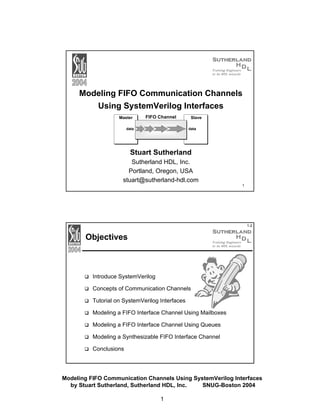
  • 1. Modeling FIFO Communication Channels Using SystemVerilog Interfaces Master FIFO Channel data Slave data Stuart Sutherland Sutherland HDL, Inc. Portland, Oregon, USA stuart@sutherland-hdl.com 1 1-2 Objectives Introduce SystemVerilog Concepts of Communication Channels Tutorial on SystemVerilog Interfaces Modeling a FIFO Interface Channel Using Mailboxes Modeling a FIFO Interface Channel Using Queues Modeling a Synthesizable FIFO Interface Channel Conclusions Modeling FIFO Communication Channels Using SystemVerilog Interfaces by Stuart Sutherland, Sutherland HDL, Inc. SNUG-Boston 2004 1
  • 2. 1-3 What is SystemVerilog? SystemVerilog extends of the IEEE 1364 Verilog standard New design modeling capabilities Abstract C language data types More accurate RTL coding Interfaces for communication New verification capabilities Assertions Race-free testbenches Object-oriented test programs SystemVerilog is the next generation of the Verilog standard Gives Verilog a much higher level of modeling abstraction Gives Verilog new capabilities for design verification Mile High View of SystemVerilog 3.1a from C / C++ mailboxes semaphores constrained random values direct C function calls classes inheritance strings dynamic arrays associative arrays references 3.0 SystemVerilog assertions test program blocks clocking domains process control interfaces nested hierarchy unrestricted ports automatic port connect enhanced literals time values and units specialized procedures packages 2-state modeling packed arrays array assignments queues unique/priority case/if compilation unit space int shortint longint byte shortreal void alias globals enum typedef structures unions casting const break continue return do–while ++ -- += -= *= /= >>= <<= >>>= <<<= &= |= ^= %= Verilog-2001 ANSI C style ports generate localparam constant functions standard file I/O $value$plusargs `ifndef `elsif `line @* (* attributes *) configurations memory part selects variable part select multi dimensional arrays signed types automatic ** (power operator) Verilog-1995 modules parameters function/tasks always @ assign $finish $fopen $fclose $display $write $monitor `define `ifdef `else `include `timescale initial disable events wait # @ fork–join wire reg integer real time packed arrays 2D memory begin–end while for forever if–else repeat + = * / % >> << Modeling FIFO Communication Channels Using SystemVerilog Interfaces by Stuart Sutherland, Sutherland HDL, Inc. SNUG-Boston 2004 2
  • 3. 1-5 Verilog, SystemVerilog and SystemC Each hardware design language has unique capabilities This paper is not about what language is best This paper is on how SystemVerilog enables modeling intermodule communication at a higher level of abstraction SystemC This chart shows... Software and embedding programming SystemVerilog does not replace SystemC SystemVerilog bridges a gap between Verilog and SystemC Verilog with SystemVerilog Object Oriented programming Behavioral and transaction modeling VHDL Verilog RTL modeling Gate-level modeling Chart reflects the author’s perception of general language overlap Switch-level modeling 1-6 What’s Next Introduce SystemVerilog Concepts of Communication Channels Tutorial on SystemVerilog Interfaces Modeling a FIFO Interface Channel Using Mailboxes Modeling a FIFO Interface Channel Using Queues Modeling a Synthesizable FIFO Interface Channel Conclusions Modeling FIFO Communication Channels Using SystemVerilog Interfaces by Stuart Sutherland, Sutherland HDL, Inc. SNUG-Boston 2004 3
  • 4. 1-7 Inter-Module Communication Verilog connects models using detailed module ports Each discrete signal must be declared as a port SystemC provides communication channels Encapsulate how information is transferred between modules Allow abstract, high-level communication SystemVerilog has communication interfaces Encapsulate how information is transferred between modules A new paradigm for inter-module communication Can SystemVerilog interfaces provide the same abstract communication capabilities as SystemC channels? Can SystemVerilog interfaces be synthesized? 1-8 SystemC Channels SystemC provides channels and interfaces A “channel” encapsulates how information is transferred between blocks of a design An “interface” defines a set of methods (functions) to send and receive data through the channel There are two types of channels Built-in channels that are pre-defined in SystemC Includes FIFO, Mutex, and Semaphore channels Represent abstract communication Generally not synthesizable User-defined channels Can be modeled as abstract or at a more detailed level Can be synthesizable Modeling FIFO Communication Channels Using SystemVerilog Interfaces by Stuart Sutherland, Sutherland HDL, Inc. SNUG-Boston 2004 4
  • 5. 1-9 A SystemC FIFO Channel FIFOs are typically used to communicate between design blocks that operate on different, asynchronous clocks The SystemC built-in FIFO channel: Is unsized — any amount of data can be in the channel Is untyped — any data type can be sent through the channel Provides write/read methods to send data through the channel Methods are built-in — end user does not see how they work MASTER module read method packet data packet ... write pointer write method SLAVE module data packet data packet read pointer packet 1-10 What’s Next Introduce SystemVerilog Concepts of Communication Channels Tutorial on SystemVerilog Interfaces Modeling a FIFO Interface Channel Using Mailboxes Modeling a FIFO Interface Channel Using Queues Modeling a Synthesizable FIFO Interface Channel Conclusions Modeling FIFO Communication Channels Using SystemVerilog Interfaces by Stuart Sutherland, Sutherland HDL, Inc. SNUG-Boston 2004 5
  • 6. 1-11 Inter-Module Communication: Verilog Style module MASTER (input clock, inout [31:0] data, output [15:0] address, output request, input grant, are in the module input ready ); Verilog connects modules at Connection details the implementation level MASTER module SLAVE module data ... address module SLAVE request grant Connection details are duplicated in other modules ready clock (input clock, inout [31:0] data, input [15:0] address, input request, output grant, output ready ); ... I want to be an engineer, not a typist! module top (input clock); wire [31:0] data, wire [15:0] address, Netlists must duplicate wire request, grant, ready; the connection detail (yet again) MASTER i1 (clock, data, address, request, grant, ready); SLAVE i2 (clock, data, address, request, grant, ready); endmodule 1-12 Inter-Module Communication: SystemVerilog Style Interfaces encapsulate inter-module communication MASTER module BUS data address request grant SLAVE module ready clock Now I can concentrate on designing instead of typing! Connection details interface BUS; are in the interface wire [31:0] data; logic [15:0] address; logic request, grant, ready; endinterface module MASTER (interface io_bus); ... endmodule module SLAVE (interface io_bus); ... Modules and netlist do not endmodule duplicate the connection details module top (input clock); instantiate the interface BUS io (); (io is the instance name) MASTER i1 (io, clock); SLAVE i2 (io, clock); endmodule connect interface instance to module port Modeling FIFO Communication Channels Using SystemVerilog Interfaces by Stuart Sutherland, Sutherland HDL, Inc. SNUG-Boston 2004 6
  • 7. 1-13 Interface Modports The module’s port direction definitions are moved to within the interface, using the modport keyword (for “module’s ports”) Encapsulates port lists that used to be scattered in many modules MASTER module BUS data address request grant ready interface BUS ; wire [31:0] data; logic [15:0] address; logic request, grant, ready; SLAVE module modport master_ports (inout output output input input data, address, request, grant, ready ); modport slave_ports data, address, request, grant, ready ); A modport defines the port directions from the module’s point of view clock (inout input input output output endinterface Selecting Which Modport Definition To Use 1-14 SystemVerilog has two ways to select which modport to use At the module instance — allows “generic module ports” interface BUS; modport master_ports (...) modport slave_ports (...) endinterface Each instance of the module can be connected to a different interface or a different modport module MASTER (interface io_bus); ... endmodule connect to interface using module top (input clock); the master_ports port list BUS io (); MASTER i1 (io.master_ports, clock); ... endmodule At the module instance — prevents incorrect corrections interface BUS; modport master_ports (...) modport slave_ports (...) endinterface Hard coded interface port means each instance of the module will be connected the same way module SLAVE (BUS.slave_ports io_bus); ... connect to interface using endmodule the slave_ports port list module top (input clock); BUS io (); ... SLAVE i2 (io, clock); endmodule Modeling FIFO Communication Channels Using SystemVerilog Interfaces by Stuart Sutherland, Sutherland HDL, Inc. SNUG-Boston 2004 7
  • 8. 1-15 Interface Methods Interfaces can contain “methods” Defined using Verilog/SystemVerilog tasks and functions Used to encapsulate inter-module communication functionality interface BUS; ... task Read (...); Methods encapsulate communication functionality into one place, instead of being fragmented across multiple modules ... endtask task Write (...); communication methods ... endtask function bit ParityGen (...); ... endfunction modules can import interface methods through modports modport master_ports (import Read, Write, input ... ); modport slave_ports (import Read, Write, ParityGen, input ... ); endinterface Referencing Signals and Methods In An Interface 1-16 Modules can reference signals and methods within the interface using a hierarchical path name <interface_port_name>.<signal_or_method_name> interface port name module MASTER (interface io_bus); // interface port ... always @(posedge clock) begin if (io_bus.request) reference signal in interface io_bus.Read(...); ... end reference method in interface ... endmodule Synthesis supports this special case of using hierarchical path names Modeling FIFO Communication Channels Using SystemVerilog Interfaces by Stuart Sutherland, Sutherland HDL, Inc. SNUG-Boston 2004 8
  • 9. 1-17 Interface Processes An interface can contain procedural code and continuous assignments initial, always, always_ff, always_comb, always_latch, assign Processes encapsulate communication functionality that might otherwise be spread across several modules interface fifo_channel ; ... // calculate fifo_empty flag always_ff @(posedge read_clock, negedge read_resetN) begin if (!read_resetN) fifo_empty <= 0; else fifo_empty <= (rd_ptr_next == rd_ptr_synced); end ... endinterface 1-18 Parameterized Interfaces Interfaces can be parameterized, the same as Verilog modules Allows each instance of an interface to be reconfigured interface fifo_channel #(parameter FifoSize = 8, PtrSize = 4, parameter type DataType = int ); ... DataType write_data; SystemVerilog also allows DataType read_data; data types to be parameterized ... endinterface module top_level (input clock, resetN); ... fifo_channel #(.DataType(real)) FIFO (); ... interface instance is reconfigured endmodule to use a different data type Modeling FIFO Communication Channels Using SystemVerilog Interfaces by Stuart Sutherland, Sutherland HDL, Inc. SNUG-Boston 2004 9
  • 10. 1-19 The FIFO Example Data Types The FIFO examples used in this paper transport packets for an ATM Switch CLP ... NNI Cell GFC VPI11-4 VPI3-0 VCI15-12 VCI11-4 VCI3-0 PT HEC Payload 0 Payload 47 CLP ... UNI Cell GFC VPI7-4 VPI3-0 VCI15-12 VCI11-4 VCI3-0 PT HEC Payload 0 typedef struct { // UNI Cell bit [ 3:0] GFC; bit [ 7:0] VPI; SystemVerilog adds bit [15:0] VCI; structures and userbit CLP; defined types to Verilog bit [ 2:0] T; bit [ 7:0] HEC; bit [0:47] [ 7:0] Payload; } uniType; typedef struct { // NNI Cell bit [11:0] VPI; bit [15:0] VCI; bit CLP; bit [ 2:0] PT; bit [ 7:0] HEC; bit [0:47] [ 7:0] Payload; } nniType; Payload 47 1-20 What’s Next Introduce SystemVerilog Concepts of Communication Channels Tutorial on SystemVerilog Interfaces Modeling a FIFO Interface Channel Using Mailboxes Modeling a FIFO Interface Channel Using Queues Modeling a Synthesizable FIFO Interface Channel Conclusions Modeling FIFO Communication Channels Using SystemVerilog Interfaces by Stuart Sutherland, Sutherland HDL, Inc. SNUG-Boston 2004 10
  • 11. 1-21 FIFO Channel Example 1: An Abstract Version The first FIFO interface example in this paper is modeled at a high level of abstraction Closely approximates a SystemC FIFO built-in channel Requires very few lines of code to model The FIFO storage is modeled using SystemVerilog mailboxes MASTER module packet write pointer write method read method ... data packet SLAVE module data packet data packet read pointer packet built-in mailbox methods will be used for writing and reading the FIFO 1-22 Mailboxes A mailbox is a communication mechanism where data can be sent to a mailbox by one process and retrieved by another SystemVerilog mailboxes behave like real mailboxes When a letter is delivered to a mailbox, the letter can be retrieved If the post has not yet been delivered, a process can: Choose to wait for post delivery, or Come back later and check again Mailboxes can be either bounded or unbounded A bounded mailbox is full when it contains a maximum number of messages A process attempting to place a message into a full mailbox must wait until there is room available in the mailbox queue Unbounded mailboxes never suspend send operations Modeling FIFO Communication Channels Using SystemVerilog Interfaces by Stuart Sutherland, Sutherland HDL, Inc. SNUG-Boston 2004 11
  • 12. Overview of SystemVerilog Mailboxes 1-23 SystemVerilog has a predefined object-oriented mailbox class A communication mechanism whereby Messages can be placed in a mailbox by one process... ...and retrieved by another process If there are no messages in the mailbox, the retrieving process can: Suspend and wait for a message (block) Come back later and check again 1-24 Mailbox Capacity A mailbox is a built-in class object A new mailbox is “constructed” using a new function construct a mailbox called “FIFO_1” mailbox FIFO_1 = new; The mailbox size can be unbounded or bounded An unbounded mailbox is never full A bounded mailbox has a max number of messages it can hold A process attempting to place a message into a full mailbox must wait until there is room available in the mailbox The size of the mailbox is passed as an argument to new construct a bounded mailbox mailbox FIFO_2 = new(8); SystemC built-in FIFOs are unbounded, but the example in this paper uses a bounded mailbox, which is more like hardware Modeling FIFO Communication Channels Using SystemVerilog Interfaces by Stuart Sutherland, Sutherland HDL, Inc. SNUG-Boston 2004 12
  • 13. 1-25 Mailbox Message Type A mailbox can be typeless or typed A typeless mailbox can transfer any data type The user must ensure that data is retrieved as the same data type in which it was stored Run-time errors occur if try to retrieve the wrong type A typed mailbox can only transfer data of a specific type Sending or retrieving the wrong type is a compile-time error The mailbox type is defined using parameter redefinition construct a typed mailbox mailbox #(int) FIFO_3 = new(8); SystemC built-in FIFOs are typeless, but the example in this paper uses a typed mailbox, which is more like hardware 1-26 Blocking Mailbox Methods SystemVerilog mailboxes have several built-in methods put(message) — places a message in a mailbox If the mailbox is full, the process is suspended (blocked) until there is room in the mailbox to place the message get(variable) — retrieves a message from a mailbox If the mailbox is empty, the process is suspended (blocked) until a message is placed in the mailbox mailbox #(int) FIFO = new(8); int data_in; always @(posedge write_clock) begin if (data_ready) FIFO.put(data_in); end int data_out; always @(posedge read_clock) begin FIFO.get(data_out); A run-time error occurs if the data type passed to end get() does not match the data type in the mailbox Modeling FIFO Communication Channels Using SystemVerilog Interfaces by Stuart Sutherland, Sutherland HDL, Inc. SNUG-Boston 2004 13
  • 14. 1-27 Nonblocking Mailbox Methods Mailboxes can be used without blocking process execution status = tryput(message) — similar to put(), except that the process does not suspend if the mailbox is full Returns 0 if the mailbox is full; the message is not delivered Returns 1 if the mailbox is not full; the message is delivered status = tryget(variable) — similar to get(), except that the process will not suspend if the mailbox is empty Returns 0 if the mailbox is empty Returns 1 if the mailbox is not empty and the message type matches the argument type Returns -1 if not empty, but the message type does not match between the argument type There are additional mailbox methods that are not covered in this presentation 1-28 A FIFO Channel Model Using Interfaces and Mailboxes interface fifo_channel_1 #(parameter FifoSize = 8, parameter type DataType = uniType); parameterized size and type DataType write_data; DataType read_data; bit fifo_empty, fifo_full; mailbox #(DataType) FIFO = new(FifoSize); storage is a bounded, typed mailbox function automatic void Write (input DataType write_data); void'(FIFO.tryput(write_data)); fifo_full = ~(FIFO.num < FifoSize); endfunction function automatic void Read (output DataType read_data); fifo_empty = (FIFO.num == 0); void'(FIFO.tryget(read_data) ); endfunction modport sender (input write_data, output fifo_full, import Write); modport reader (output read_data, output fifo_empty, import Read); write/read methods are encapsulated in the interface module port lists are encapsulated in the interface endinterface: fifo_channel_1 Modeling FIFO Communication Channels Using SystemVerilog Interfaces by Stuart Sutherland, Sutherland HDL, Inc. SNUG-Boston 2004 14
  • 15. Connecting and Using the FIFO Interface Channel 1-29 “processor1” places data into the FIFO channel module processor1 #(parameter type DataType = uniType) (fifo_channel_1.sender fifo, interface port input clock, write_resetN); DataType data_packet; always_ff @(posedge clock) if (write_enable && !fifo.fifo_full) call to interface method fifo.Write(data_packet); ... “processor2” retrieves data from the FIFO channel module processor2 #(parameter type DataType = uniType) (fifo_channel_1.reader fifo, interface port input clock, resetN); DataType data_packet; always_ff @(posedge clock) if (read_enable && !fifo.fifo_empty) call to interface method fifo.Read(data_packet); ... a top-level module connects the interface to the modules module top_level (input clock1, clock2, resetN); instance of interface fifo_channel_1 #(.DataType(nniType)) FIFO (); processor1 #(.DataType(nniType)) p1 (FIFO, clock1, resetN); processor2 #(.DataType(nniType)) p2 (FIFO, clock2, resetN); endmodule: top_level connect the interface Synthesis Considerations of the FIFO Mailbox Model 1-30 SystemVerilog mailboxes are not synthesizable HDL Compiler (front-end to DC) does not currently support SystemVerilog’s object-oriented programming Mailboxes do not have the level of detail needed to implement clock domain crossing FIFO logic But don’t despair — this abstract model is still valuable! • Easy and fast to model • Can be used to verify inter-module communications • Can be used to verify FIFO size at various clock speeds The next few pages show another way to model a FIFO interface channel Modeling FIFO Communication Channels Using SystemVerilog Interfaces by Stuart Sutherland, Sutherland HDL, Inc. SNUG-Boston 2004 15
  • 16. 1-31 What’s Next Introduce SystemVerilog Concepts of Communication Channels Tutorial on SystemVerilog Interfaces Modeling a FIFO Interface Channel Using Mailboxes Modeling a FIFO Interface Channel Using Queues Modeling a Synthesizable FIFO Interface Channel Conclusions FIFO Channel Example 2: Using SystemVerilog Queues 1-32 SystemVerilog adds dynamic queues to Verilog A dynamic array — can grow and shrink in size during simulation Can represent FIFO, LIFO or other types of queues A queue is declared like an array, but using $ for the range Optionally, a maximum size for the queue can be specified int q1 [$]; an empty queue, with an unbounded size int q2 [$] = {1,2,3,5,8}; unbounded queue, initialized with 5 locations typedef struct {int a, b; bit flag} packet_t; packet_t q3 [$:16]; a bounded queue, with a maximum size of 16 A queue can only hold one data type, which is specified when the queue is declared Modeling FIFO Communication Channels Using SystemVerilog Interfaces by Stuart Sutherland, Sutherland HDL, Inc. SNUG-Boston 2004 16
  • 17. 1-33 Queue Methods SystemVerilog queues have several built-in methods push_front(<value>) — adds a new location at the beginning of the queue with the value push_back(<value>) — adds a new location at the end of the queue with the value variable = pop_front() — removes the first element of the queue and returns its value variable = pop_back() — removes the last element of the queue and returns its value insert(<index>,<value>) — changes the value of a queue location without changing the queue size variable = <queue_name>[<index>] — retrieves the value of a queue location without changing the queue size variable = size() — returns the current number of elements in the queue It is a run-time error to write to a full queue or to read from an empty queue 1-34 A FIFO Channel Model Using Interfaces and Queues interface fifo_channel_2 #(parameter FifoSize = 8, parameter type DataType = uniType); parameterized size and type DataType write_data; DataType read_data; bit fifo_empty, fifo_full; DataType FIFO [$:FifoSize]; storage is a bounded queue function automatic void Write (input DataType write_data); FIFO.push_back(write_data); fifo_full = ~(FIFO.PtrSize < FifoSize); endfunction function automatic void Read (output DataType read_data); read_data = FIFO.pop_front; fifo_empty = (FIFO.PtrSize == 0); endfunction modport sender (input write_data, output fifo_full, import Write); modport reader (output read_data, output fifo_empty, import Read); write/read method names are the same as previous example modport definitions are the same as previous example endinterface: fifo_channel_2 Modeling FIFO Communication Channels Using SystemVerilog Interfaces by Stuart Sutherland, Sutherland HDL, Inc. SNUG-Boston 2004 17
  • 18. Connecting and Using the FIFO Interface Example 2 1-35 The second FIFO example can be used in the same way as the first example The modport definitions are exactly the same The method names are exactly the same The method formal arguments are the same the FIFO mailbox example and the FIFO-queue example are completely interchangeable module top_level (input clock1, clock2, resetN); fifo_channel_1 #(.DataType(nniType)) FIFO (); instance of interface fifo_channel_2 #(.DataType(nniType)) FIFO (); processor1 #(.DataType(nniType)) p1 (FIFO, clock1, resetN); processor2 #(.DataType(nniType)) p2 (FIFO, clock2, resetN); endmodule: top_level 1-36 Queues versus Mailboxes Is there an advantage to modeling the FIFO with a SystemVerilog queue instead of a mailbox? Yes! SystemVerilog queues are arrays, instead of abstract objects, and therefore are synthesizable. Mailbox advantages for representing a FIFO Very easy to model Closely approximates the methods in SystemC FIFO channels Intuitive to use at a system level or testbench level of design Queue advantages for representing a FIFO Easy to model at an abstract level More closely approximates a hardware FIFO Can be synthesizable (more about this on the next page) Modeling FIFO Communication Channels Using SystemVerilog Interfaces by Stuart Sutherland, Sutherland HDL, Inc. SNUG-Boston 2004 18
  • 19. Synthesis Considerations of the FIFO Queue Model 1-37 The SystemVerilog queue construct is synthesizable, but... HDL Compiler does not yet support queues (as of July 2004) The write and read methods are too abstract Do not contain the information needed to properly synthesize cross domain clock synchronization FIFO synchronization is covered in two SNUG papers from 2002 “Simulation and Synthesis Techniques for Asynchronous FIFO Design”, by Cliff Cummings “Simulation and Synthesis Techniques for Asynchronous FIFO Design with Asynchronous Pointer Comparisons”, by Cliff Cummings and Peter Alfke These papers can be downloaded from www.sunburst-design.com/papers 1-38 What’s Next Introduce SystemVerilog Concepts of Communication Channels Tutorial on SystemVerilog Interfaces Modeling a FIFO Interface Channel Using Mailboxes Modeling a FIFO Interface Channel Using Queues Modeling a Synthesizable FIFO Interface Channel Conclusions Modeling FIFO Communication Channels Using SystemVerilog Interfaces by Stuart Sutherland, Sutherland HDL, Inc. SNUG-Boston 2004 19
  • 20. 1-39 Synthesizing Interfaces The Synthesis process: Expands an interface port to separate ports (using the modport port list) Makes local copies of the imported methods (tasks and functions) Requires that the methods be declared as automatic interface BUS ; bit request, grant; task automatic Read(...); RTL module MASTER (BUS.master_ports a, input clock ); Model ... ... endtask modport master_ports (output request, input grant, import Read ); endinterface endinterface Synthesized module MASTER (output request, input grant, Model input clock ); ... endinterface synthesized copy of the Read task Modeling a Synthesizable FIFO Channel 1-40 To be synthesizable, a FIFO model must have: RTL level clock synchronizers FIFOs are typically used to transfer data between domains running on different, asynchronous clocks Add RTL level full and empty flag generation Full and empty flags can be affected by different clocks, and therefore require extra hardware The advantages of abstract queues can be maintained The interface still encapsulates the communication details Modules still communicate by calling write and read methods Queue methods can be used instead of RTL write pointers and read pointers (maybe) It remains to be proven as to how well synthesis will implement queue methods... Modeling FIFO Communication Channels Using SystemVerilog Interfaces by Stuart Sutherland, Sutherland HDL, Inc. SNUG-Boston 2004 20
  • 21. 1-41 Synthesizable FIFO Using Queues and RTL Code interface fifo_channel_3 #(parameter FifoSize = 8, parameter type DataType = uniType); parameterized size and type DataType write_data; DataType read_data; bit fifo_empty, fifo_full; DataType FIFO [$:FifoSize]; storage is a bounded queue, same as previous example function automatic void Write (input DataType write_data); FIFO.push_back(write_data); endfunction function automatic void Read (output DataType read_data); read_data = FIFO.pop_front; endfunction write/read methods only push/pop data (full and empty flags are set using RTL code, on next page) modport sender (input write_data, output fifo_full, write_clock, write_enable, write_resetN, import Write, // internal signals used within the interface inout wr_ptr, wr_ptr_synced, wr_ptr_next, wr_cntr, wr_cntr_next, wr_ptr_2nd_msb, wr_ptr_synced_2nd_msb ); modport definitions are more detailed than previous example to support RTL code modport reader (...); (example continued on next slide) Synthesizable FIFO (continued) always_ff @(posedge write_clock, negedge write_resetN) if (!write_resetN) {wr_ptr_synced,wr_ptr} <= 0; else {wr_ptr_synced,wr_ptr} <= {wr_ptr,rd_ptr}; always_ff @(posedge read_clock, negedge read_resetN) if (!read_resetN) {rd_ptr_synced,rd_ptr} <= 0; else {rd_ptr_synced,rd_ptr} <= {rd_ptr,wr_ptr}; always_ff @(posedge write_clock, negedge write_resetN) if (!write_resetN) wr_ptr <= 0; else wr_ptr <= wr_ptr_next; always_comb begin for (int i=0; i<=PtrSize; i++) wr_cntr[i] = ^(wr_ptr>>i); if (!fifo_full && write_enable) wr_cntr_next = wr_cntr + 1; else wr_cntr_next = wr_cntr; wr_ptr_next = (wr_cntr_next>>1)^wr_cntr_next; end 1-42 clock synchronization write control assign wr_ptr_2nd_msb = wr_ptr_next[PtrSize]^wr_ptr_next[PtrSize-1]; assign wr_ptr_synced_2nd_msb = wr_ptr_synced[PtrSize]^wr_ptr_synced[PtrSize-1]; always_ff @(posedge write_clock, negedge write_resetN) fifo_full logic if (!write_resetN) fifo_full <= 0; else fifo_full <= ((wr_ptr_next[PtrSize] != wr_ptr_synced[PtrSize]) && (wr_ptr_2nd_msb == wr_ptr_synced_2nd_msb ) && (wr_ptr_next[PtrSize-2:0] == wr_ptr_synced[PtrSize-2:0]) ); (example continued on next slide) Modeling FIFO Communication Channels Using SystemVerilog Interfaces by Stuart Sutherland, Sutherland HDL, Inc. SNUG-Boston 2004 21
  • 22. 1-43 Synthesizable FIFO (continued) always_ff @(posedge read_clock, negedge read_resetN) if (!read_resetN) rd_ptr <= 0; else rd_ptr <= rd_ptr_next; always_comb begin for (int i=0; i<=PtrSize; i++) rd_cntr[i] = ^(rd_ptr>>i); if (!fifo_empty && read_enable) rd_cntr_next = rd_cntr + 1; else rd_cntr_next = rd_cntr; rd_ptr_next = (rd_cntr_next>>1)^rd_cntr_next; end always_ff @(posedge read_clock, negedge read_resetN) begin if (!read_resetN) fifo_empty <= 0; else fifo_empty <= (rd_ptr_next == rd_ptr_synced); end read control fifo_empty logic endinterface: fifo_channel_3 1-44 What’s The Point? If writing a synthesizable RTL FIFO Interface takes so much code, why not just leave the RTL logic in the modules? • Interfaces represent inter-module communication • a FIFO in a module is another design hierarchy block • Interfaces simplify module connections to the FIFO • One interface port instead of dozens of ports • Interfaces encapsulate communication methods • Inter-connecting modules call interface methods instead of using discrete signals • Abstract and RTL interfaces are easily interchangeable Modeling FIFO Communication Channels Using SystemVerilog Interfaces by Stuart Sutherland, Sutherland HDL, Inc. SNUG-Boston 2004 22
  • 23. 1-45 Connecting and Using the RTL/Queue FIFO Interface The RTL/queue FIFO interface is almost interchangeable with the abstract FIFO interfaces The method names are the same The method formal arguments are the same But..., the modport definitions are not the same, because the RTL needs additional signals, such as clock and reset module processor1 #(parameter type DataType = uniType) (fifo_channel_3.sender fifo, input clock, write_resetN); DataType data_packet; always_ff @(posedge fifo.clock) if (write_enable && !fifo.fifo_full) fifo.Write(data_packet); ... Clock and reset are part of the interface, instead of separate module ports The methods and other FIFO signals are the same as with the abstract FIFO Is there a way to make the models completely interchangeable? Yes, clock and reset could also have been part of the abstract FIFO models (even if not used inside the interface) 1-46 Synthesis Considerations Synthesis places some restrictions on interfaces and queues that should be noted These restrictions are NOT part of the SystemVerilog standard! Interface declaration order Synthesis must compile the interface and the module using the interface together, with the interface read in first Methods must be automatic Tasks and functions in an interface that are called by modules must be automatic, so that each module sees a local copy Internal interface signals must be included in modports Signals directly and indirectly referenced by a module must be listed in the module’s modport list Queues not yet implemented At the time this paper was written, neither VCS nor HDL Compiler were supporting SystemVerilog queues Examples were tested using static arrays as a work around) Modeling FIFO Communication Channels Using SystemVerilog Interfaces by Stuart Sutherland, Sutherland HDL, Inc. SNUG-Boston 2004 23
  • 24. 1-47 What’s Next Introduce SystemVerilog Concepts of Communication Channels Tutorial on SystemVerilog Interfaces Modeling a FIFO Interface Channel Using Mailboxes Modeling a FIFO Interface Channel Using Queues Modeling a Synthesizable FIFO Interface Channel Conclusions 1-48 Conclusions Verilog inter-module communication is at a low-level SystemVerilog adds interfaces to Verilog High-level inter-module communication Encapsulates communication details in one place Eliminates port declaration redundancy SystemC provides abstract communications channels, such as FIFOs, mutex, and semaphores The built-in SystemC channels are not synthesizable SystemVerilog interfaces can effectively model the behavior of SystemC channels Can be simple and abstract, but not synthesizable Can be more detailed, to be synthesizable Modeling FIFO Communication Channels Using SystemVerilog Interfaces by Stuart Sutherland, Sutherland HDL, Inc. SNUG-Boston 2004 24
  • 25. 1-49 Future Work Make the three interface examples fully interchangeable The method names and arguments are already the same The modports need to be the same Add assertions to the interface Assert that no writes are made to a full FIFO Assert that no reads are made to an empty FIFO Prove that the mixed RTL/queue example is synthesizable Waiting for HDL Compiler to implement the queue construct and queue methods 1-50 Questions? Modeling FIFO Communication Channels Using SystemVerilog Interfaces by Stuart Sutherland, Sutherland HDL, Inc. SNUG-Boston 2004 25