Synchronous generator
•
0 gefällt mir•1,291 views

Synchronous generators operate on the principle of electromagnetic induction. They have a stationary armature winding and a rotating field winding supplied by a direct current source. It is advantageous to have the field winding on the rotor and armature winding on the stator because it allows for easier insulation of the high voltage winding and direct connection to the load. The frequency of the induced voltage depends on the number of rotor poles and its rotational speed. Armature reaction is the effect of the armature magnetic field on the main rotor field, distorting or strengthening it depending on the load power factor.

Empfohlen
Weitere ähnliche Inhalte
Was ist angesagt?
Was ist angesagt? (20)
Ähnlich wie Synchronous generator
Ähnlich wie Synchronous generator (20)
Mehr von Dr.Raja Masood Larik
Mehr von Dr.Raja Masood Larik (20)
Kürzlich hochgeladen
Kürzlich hochgeladen (20)
Synchronous generator
- 2. 2 SYNCHRONOUS GENERATOR • Synchronous generator operates on the principle that when the magnetic flux linking a conductor changes, an e.m.f. is induced in the conductor. • It has an armature winding and a field winding, • It is more convenient and advantageous to place the field winding on the rotor and armature winding on the stator. Introduction Lecture Notes by Dr.R.M.Larik
- 3. 3 SYNCHRONOUS GENERATOR • It is easier to insulate stationary winding for higher voltages because they are not subjected to centrifugal forces and also extra space is available due to the stationary arrangement of the armature. • The stationary 3-phase armature can be directly connected to load without going through large, unreliable slip rings and brush-gear. • Since the excitation current is much smaller as compared to load current, the slip rings and brush gear required are of light construction. • Due to simple and robust construction of the rotor, higher speed of rotating d.c. field is possible. Advantages of Stationary Armature Lecture Notes by Dr.R.M.Larik
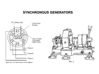
- 4. 4 CONSTRUCTION OF SYNCHRONOUS GENERATOR • It is the stationary part of the machine and is built up of sheet-steel laminations having slots on its inner periphery. • A 3-phase winding is placed in these slots and serves as the armature winding of the alternator. • The armature winding is connected in star with neutral grounded. Stator Rotor • The rotor carries a field winding supplied with direct current through the slip rings by a separate d.c. source. • This d.c. source (exciter) is generally a small d.c. generator mounted on the shaft of the alternator. • Rotor construction is of salient (projected) pole type and non- salient (cylindrical) pole typeLecture Notes by Dr.R.M.Larik
- 5. 5 CONSTRUCTION OF SYNCHRONOUS GENERATOR (Contd.) Rotor (Contd.) • In this type, salient or projected poles are mounted on a large circular steel frame which is fixed to the shaft of the alternator. • The individual field pole windings are connected in series such that when the field winding is energized by the exciter, adjacent poles have opposite polarities. Salient Pole Type Lecture Notes by Dr.R.M.Larik
- 6. 6 CONSTRUCTION OF SYNCHRONOUS GENERATOR (Contd.) Rotor (Contd.) • Low and medium-speed alternators (120-400 r.p.m.), those driven by diesel engines or water turbines, have salient pole type rotors due to the following reasons: − The salient field poles would cause an excessive windage loss if driven at high speed and would tend to produce noise. − Salient-pole construction cannot be made strong enough to withstand the mechanical stresses to which they may be subjected at higher speeds. Salient Pole Type (Contd.) • For a frequency of 50 Hz, we must use a large number of poles on the rotor of slow-speed alternators. • Low-speed rotors possess a large diameter to provide necessary space for the poles.Lecture Notes by Dr.R.M.Larik
- 7. 7 CONSTRUCTION OF SYNCHRONOUS GENERATOR (Contd.) Rotor (Contd.) • Non-salient pole type rotor is made of smooth solid forged-steel cylinder having a number of slots along the outer surface. • Field windings are embedded in the slots and are connected in series to the slip rings through which they are energized by the d.c. exciter. • The regions forming the poles are left unslotted. Non-Salient Pole Type Lecture Notes by Dr.R.M.Larik
- 8. 8 CONSTRUCTION OF SYNCHRONOUS GENERATOR (Contd.) Rotor (Contd.) • High-speed generators (1500 or 3000 r.p.m.), driven by steam turbines, use non-salient type rotors due to the reasons: − It gives noiseless operation at high speeds. − The flux distribution around the periphery is nearly a sine wave and hence a better e.m.f. waveform is obtained than in the case of salient-pole type. • Since steam turbines run at high speed and a frequency of 50 Hz is required, we need a small number of poles on the rotor. • We can not use less than 2 poles, hence, the highest possible speed will be 3000 r.p.m. Non-Salient Pole Type (Contd.) Lecture Notes by Dr.R.M.Larik
- 9. 9 OPERATION • The rotor winding is energized from the d.c. exciter and alternate N and S poles are developed on the rotor. • When the rotor is rotated in anti-clockwise direction by a prime mover, the stator or armature conductors are cut by the magnetic flux of rotor poles. • Consequently, e.m.f. is induced in the armature conductors due to electromagnetic induction. • The induced e.m.f. is alternating since N and S poles of rotor alternately pass the armature conductors. • Direction of the induced e.m.f. can be determined by Fleming’s right hand rule and the frequency is given by; f = NP/120 where N = speed of rotor in r.p.m. P = number of rotor polesLecture Notes by Dr.R.M.Larik
- 10. 10 OPERATION (Contd.) • Magnitude of the voltage induced in each phase depends upon the rotor magnetic flux, the number and position of the conductors in the phase and the speed of the rotor. • Magnitude of induced e.m.f. depends upon the speed of rotation and the d.c. exciting current. • Magnitude of e.m.f. in each phase of stator winding is same, however, they differ in phase by 120° electrical. Lecture Notes by Dr.R.M.Larik
- 11. 11 FREQUENCY • Frequency of induced e.m.f. in the stator depends on speed and the number of poles. Let N = rotor speed in r.p.m. P = number of rotor poles f = frequency of e.m.f. in Hz • Consider a stator conductor that is successively swept by the N and S poles of the rotor. • If a positive voltage is induced when a N-pole sweeps across the conductor, a similar negative voltage is induced when a S-pole sweeps. Lecture Notes by Dr.R.M.Larik
- 12. 12 FREQUENCY (Contd.) • Thus one complete cycle of e.m.f. is generated in the conductor as a pair of poles passes it. No. of cycles/revolution = No. of pairs of poles = P/2 No. of revolutions/second = N/60 No. of cycles/second = (P/2)(N/60) = N P/120 But number of cycles of e.m.f. per second is its frequency. f = NP/120 N is the synchronous speed generally represented by Ns • For a given alternator, the number of rotor poles is fixed, hence, the alternator must run at synchronous speed to give the desired frequency. • For this reason, an alternator is also called synchronous generator. Lecture Notes by Dr.R.M.Larik
- 13. 13 A.C. ARMATURE WINDINGS • A.C. armature windings are generally open-circuit type i.e., both ends are brought out. • An open-circuit winding is one that does not close on itself i.e., a closed circuit will not be formed until some external connection is made to a source or load. • The following are the general features of a.c. armature windings: − A.C. armature windings are symmetrically distributed in slots around the complete circumference of the armature. − Distributed winding has two principal advantages: a) Distributed winding generates a voltage in the form of sin wave. b) Copper is evenly distributed on the armature surface resulting in uniform heating of winding which can be easily cooled. Lecture Notes by Dr.R.M.Larik
- 14. 14 A.C. ARMATURE WINDINGS (Contd.) − A.C. armature windings may use full-pitch coils or fractional-pitch coils − A coil with a span of 180° electrical is called a full-pitch coil with two sides of the coil occupyng identical positions under adjacent opposite poles and the e.m.f. generated in the coil is maximum. − A coil with a span of less than 180° electrical is called a fractional- pitch coil (For example, a coil with a span of 150° electrical would be called a 5/6 pitch coil) and the e.m.f. induced in the coil will be less than that of a full-pitch coil. − Most of a.c. machines use double layer armature windings i.e. one coil side lies in the upper half of one slot while the other coil side lies in the lower half of another slot spaced about one-pole pitch from the first one. Lecture Notes by Dr.R.M.Larik
- 15. 15 E.M.F. EQUATION Let Z = No. of conductors or coil sides in series per phase = Flux per pole in webers P = Number of rotor poles N = Rotor speed in r.p.m. In one revolution (60/N second), each stator conductor is cut by P webers i.e., d = P; and dt = 60/N Average e.m.f. induced in one stator conductor = dϕ dt = Pϕ Τ60 N = PϕN 60 volts Since there are Z conductors in series per phase, Average e.m.f. /phase = PϕN 60 x Z = PϕZ 60 x 120 f P N = 120 f P = 2 f Z VoltsLecture Notes by Dr.R.M.Larik
- 16. 16 E.M.F. EQUATION R.M.S. value of e.m.f./phase = Average value of e.m.f. per phase x form factor = 2 f Z x 1.11 = 2.22 f Z Volts E r.m.s. per phase = 2.22 f Z volts (i) If Kp and Kd are the pitch factor and distribution factor of the armature winding, then, E r.m.s. per phase = 2.22 Kp Kd f Z Volts (ii) Sometimes the turns (T) per phase rather than conductors per phase are specified, in that case, eq. (ii) becomes: E r.m.s. per phase = 4.44 Kp Kd f T Volts (iii) The line voltage will depend upon whether the winding is star or delta connected. Lecture Notes by Dr.R.M.Larik
- 17. 17 ARMATURE REACTION • When an alternator is running at no-load, there will be no current flowing through the armature winding and magnetic flux produced in the air-gap will be only due to rotor field. • When the alternator is loaded, the three-phase currents will produce an additional magnetic field in the air-gap. • The effect of armature flux on the flux produced by field ampere-turns is called armature reaction. • The armature flux and the flux produced by rotor ampere-turns rotate at a synchronous speed in the same direction, hence, the two fluxes are fixed in space relative to each other. • Modification of flux in the air-gap due to armature flux depends on the magnitude of stator current and on the power factor of the load. • Load power factor determines whether the armature flux distorts, opposes or helps the main flux. Lecture Notes by Dr.R.M.Larik
- 18. 18 ARMATURE REACTION • When armature is on open-circuit, there is no stator current and the flux due to rotor current is distributed symmetrically in the air-gap • Since the direction of the rotor is assumed clockwise, the generated e.m.f. in phase R1R2 is at its maximum and is towards the paper in the conductor R1 and outwards in conductor R2. Load at Unity Power Factor • No armature flux is produced since no current flows in the armature winding. Lecture Notes by Dr.R.M.Larik
- 19. 19 ARMATURE REACTION (Contd.) • In case a resistive load (unity p.f.) is connected across the terminals of the alternator, according to right- hand rule, the current is “in” in the conductors under N-pole and “out” in the conductors under S-pole. • Therefore, the armature flux is clockwise due to currents in the top conductors and anti-clockwise due to currents in the bottom conductors. Load at Unity Power Factor (Contd.) • The armature flux is at 90° to the main flux (due to rotor current) and is behind the main flux. Lecture Notes by Dr.R.M.Larik
- 20. 20 ARMATURE REACTION (Contd.) • In this case, the flux in the air-gap is distorted but not weakened. • Therefore, at unity p.f., the effect of armature reaction is merely to distort the main field; there is no weakening of the main field and the average flux practically remains the same. • Since the magnetic flux due to stator currents (i.e., armature flux) rotate; synchronously with the rotor, the flux distortion remains the same for all positions of the rotor. Load at Unity Power Factor (Contd.) Lecture Notes by Dr.R.M.Larik
- 21. 21 ARMATURE REACTION (Contd.) • When a pure inductive load (zero p.f. lagging) is connected across the terminals of the alternator, current lags behind the voltage by 90°. • This means that current will be maximum at zero e.m.f. and vice-versa. Load at Zero Power Factor Lagging • Figure shows the condition when the alternator is supplying resistive load. • Note that e.m.f. as well as current in phase R1R2 is maximum in this position. Lecture Notes by Dr.R.M.Larik
- 22. 22 ARMATURE REACTION (Contd.) • When the generator is supplying a pure inductive load, the current in phase R1R2 will not reach its maximum value until N-pole advanced 90° electrical • Now the armature flux is from right to left and field flux is from left to right. Load at Zero Power Factor Lagging (Contd.) • All the flux produced by armature current (i.e., armature flux) opposes the field flux and, therefore, weakens it. • In other words, armature reaction is demagnetizing. Lecture Notes by Dr.R.M.Larik
- 23. 23 ARMATURE REACTION (Contd.) • When pure capacitive load (zero p.f. leading) is connected to the alternator, the current in armature windings will lead the induced e.m.f. by 90°. • Effect of armature reaction will be the reverse that for pure inductive load. Load at Zero Power Factor Leading • Armature flux aids the main flux and generated e.m.f. is increased. • Figure shows the condition when alternator is supplying resistive load • The e.m.f. as well as current in phase R1R2 is max in this position • When alternator is supplying pure capacitive load, the max current in R1R2 will occur 90° before occurrence of max induced e.m.f. Lecture Notes by Dr.R.M.Larik
- 24. 24 ARMATURE REACTION (Contd.) • When the generator is supplying a pure capacitive load, the maximum current in R1R2 will occur 90° electrical before the occurrence of maximum induced e.m.f. • Therefore, maximum current in phase R1R2 will occur if the position of the rotor remains 90° behind as compared to its position under resistive load Load at Zero Power Factor Leading (Contd.) • It is clear that armature flux is now in the same direction as the field flux and, therefore, strengthens it. Lecture Notes by Dr.R.M.Larik
- 25. 25 ARMATURE REACTION (Contd.) • This causes an increase in the generated voltage. • Hence at zero p.f. leading, the armature reaction strengthens the main flux. • For intermediate values of p.f, the effect of armature reaction is partly distorting and partly weakening for inductive loads. • For capacitive loads, the effect of armature reaction is partly distorting and partly strengthening. Load at Zero Power Factor Leading (Contd.) Lecture Notes by Dr.R.M.Larik
- 26. 26 ALTERNATOR EQUIVALENT CIRCUIT • All the quantities are per phase. E0 = No-load e.m.f. E = Load induced e.m.f. • E is induced e.m.f. after allowing for armature reaction. • It is equal to phasor difference of E0 and Ia XAR. • Terminal voltage V is less than E by the voltage drops in XL and Ra. E = V + Ia (Ra + j XL ) and E0 = E + Ia ( j XAR ) Lecture Notes by Dr.R.M.Larik
- 27. 27 SYNCHRONOUS REACTANCE (XS) • Sum of armature leakage reactance (XL) and reactance of armature reaction (XAR) is called synchronous reactance Xs . Xs = XL + XAR • It is a fictitious reactance employed to account for the voltage effects in the armature circuit produced by the: − actual armature leakage reactance − change in the air-gap flux caused by armature reaction. • The circuit is simplified as shown. • Synchronous impedance, Zs = Ra + j Xs Lecture Notes by Dr.R.M.Larik
- 28. 28 SYNCHRONOUS REACTANCE (XS) (Contd.) • Synchronous impedance is the fictitious impedance employed to account for the voltage effects in the armature circuit produced by the: − actual armature resistance − actual armature leakage reactance − change in the air-gap flux produced by armature reaction. • Relationship between generator output voltage and load terminal voltage is given by: E0 = V + IaZs = V + Ia (R + j Xs) Lecture Notes by Dr.R.M.Larik
- 29. 29 PHASOR DIAGRAM OF A LOADED ALTERNATOR • Consider a Y-connected alternator supplying inductive load, the load p.f. angle being ϕ. • In the last slide the figure shows the equivalent circuit of the alternator per phase i.e. all quantities are per phase. • Considering the vector diagram: AC2 = AB2 + BC2 Eo 2 = (AD + BD)2 + (BE + CE)2 Since AD = V cos ϕ, BE = DF = V sin ϕ BD = I Ra, CE = I Xs Eo 2 = (V cos ϕ + I Ra)2 + (V sin ϕ + I Xs )2 Eo = V cos ϕ + I Ra 2 V sin ϕ + I Xs 2 Lecture Notes by Dr.R.M.Larik
- 30. 30 PHASOR DIAGRAM OF A LOADED ALTERNATOR Problem 1(a): A 3-phase, star-connected alternator supplies a load of 10 MW at p.f. 0.85 lagging and at 11 kV (terminal voltage). Its resistance is 0.1 ohm per phase and synchronous reactance 0.66 ohm per phase. Calculate the e.m.f. generated per phase. Solution: F.L. output current = 10 x 106 3 x 11000 x 0.85 = 618 A I Ra drop = 618 x 0.1 = 61.8 V I XS drop = 618 x 0.66 = 408 V Terminal voltage/phase = 11,000 / 3 = 6350 V ϕ = cos -1 (0.85) = 31.8°; sin ϕ = sin 31.8° = 0.527 Lecture Notes by Dr.R.M.Larik
- 31. 31 PHASOR DIAGRAM OF A LOADED ALTERNATOR Problem 1(a): Solution (Contd.): As seen from the vector diagram I instead of V has been taken along reference vector, E0 = V cos ϕ + I Ro 2 + V sin ϕ + I Xs 2 = 6350 x 0.85 + 61.8 2 + 6350 x 0.527 + 408 2 = 6625 V Problem 1(b): A 3-phase, synchronous generator is supplying a load of 100 kW at 11 kV (terminal voltage). The p.f. of load is 0.8 lagging. The armature resistance is 0.3 ohm per phase and synchronous reactance Xs is 0.5 ohm per phase. Calculate the e.m.f. generated in alternator. Eo and V are per phase values. Lecture Notes by Dr.R.M.Larik
- 32. 32 VOLTAGE REGULATION • The voltage regulation of an alternator is defined as the change in terminal voltage from no-load to full-load (the speed and field excitation being constant) divided by full-load voltage. % Voltage regulation = No load voltage − Full load voltage Full load voltage x 100 = Eo − V V x 100 where Eo = Terminal voltage of generator at no load V = Terminal voltage of generator at full load • E0 - V is the arithmetic difference and not the phasor difference. • The factors affecting the voltage regulation of an alternator are: − i) Ia Ra drop in armature winding − ii) Ia XL drop in armature winding − iii) Voltage change due to armature reaction Lecture Notes by Dr.R.M.Larik