Digital comparators are combinational logic circuits that compare digital signals at their input terminals and produce an output depending on the condition of the inputs, such as whether input A is greater than, less than, or equal to input B. Digital comparators can compare a variable number against a constant value and produce outputs indicating the three possible conditions. They use exclusive-NOR gates to compare bit pairs and cascade single-bit comparators to compare multi-bit numbers.
1. D
Digital Comparators Navigation
Page: 8 of 8
Reset
Digital Comparators
Another common and very useful combinational logic circuit is that of the Digital Comparator circuit. Digital
or Binary Comparators are made up from standard AND, NOR and NOT gates that compare the digital
signals at their input terminals and produces an output depending upon the condition of the inputs. For
example, whether input A is greater than, smaller than or equal to input B etc.
Digital Comparators can compare a variable or unknown number for example A (A1, A2, A3, .... An, etc)
against that of a constant or known value such as B (B1, B2, B3, .... Bn, etc) and produce an output
depending upon the result. For example, a comparator of 1-bit, (A and B) would produce the following three
output conditions.
This is useful if we want to compare two values and produce an output when the condition is achieved. For
example, produce an output from a counter when a certain count number is reached. Consider the simple 1-
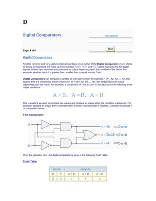
bit comparator below.
1-bit Comparator
Then the operation of a 1-bit digital comparator is given in the following Truth Table.
Truth Table
Inputs Outputs
B A A > B A = B A < B
0 0 0 1 0
2. 0 1 1 0 0
1 0 0 0 1
1 1 0 1 0
You may notice two distinct features about the comparator from the above truth table. Firstly, the circuit does
not distinguish between either two "0" or two "1"'s as an output A = B is produced when they are both equal,
either A = B = "0" or A = B = "1". Secondly, the output condition for A = B resembles that of a commonly
available logic gate, the Exclusive-NOR or Ex-NOR gate giving Q = A ⊕ B
Digital comparators actually use Exclusive-NOR gates within their design for comparing the respective
pairs of bits in each of the two words with single bit comparators cascaded together to produce Multi-bit
comparators so that larger words can be compared.
Magnitude Comparators
As well as comparing individual bits, multi-bit comparators can be constructed to compare whole binary or
BCD words to produce an output if one word is larger, equal to or less than the other. A very good example
of this is the 4-bit Magnitude Comparator. Here, two 4-bit words ("nibbles") are compared to produce the
relevant output with one word connected to inputs A and the other to be compared against connected to
input B as shown below.
4-bit Magnitude Comparator
Some commercially available Magnitude Comparators such as the 7485 have additional input terminals that
allow more individual comparators to be "cascaded" together to compare words larger than 4-bits with
magnitude comparators of "n"-bits being produced. These cascading inputs are connected directly to the
corresponding outputs of the previous comparator as shown to compare 8, 16 or even 32-bit words.
8-bit Word Comparator
3. Binary Adders Navigation
Page: 7 of 8
Reset
Binary Adders
Another common and very useful combinational logic circuit is that of the Binary Adder circuit. Binary
Adders are made up from standard AND and Ex-OR gates and allow us to "add" single bits of data
together to produce two outputs, the SUM ("S") of the addition and a CARRY ("C"). Binary adders are
mainly used in arithmetic circuits.
Consider the addition of two denary (base 10) numbers below.
123 A (Augend)
+ 789 B (Addend)
4. 912 SUM
Each column is added together starting from the right hand side. As each column is added together a carry
is generated if the result is greater or equal to ten, the base number. This carry is then added to the result of
the addition of the next column to the left and so on, simple school math's addition. Binary addition is based
on similar principals but a carry is only generated when the result in any column is greater or equal to "2",
the base number of binary.
Binary Addition
Binary Addition follows the same basic rules as for the denary addition above except in binary their are
only two digits and the largest digit is "1", so any "SUM" greater than 1 will result in a "CARRY". This carry 1
is passed over to the next column for addition and so on. Consider the single bit addition below.
0 0 1 1
+ 0 + 1 + 0 + 1
0 1 1 10
The single bits are added together and "0 + 0", "0 + 1", or "1 + 0" results in a sum of "0" or "1" until you get
to "1 + 1" then the sum is equal to "2". For a simple 1-bit addition problem like this, the resulting carry bit
could be ignored which would result in an output truth table resembling that of an Ex-OR Gate as seen in
the Logic Gates section and whose result is the sum of the two bits but without the carry. An Ex-OR gate
only produces an output "1" when either input is at logic "1", but not both. However, all microprocessors and
electronic calculators require the carry bit to correctly calculate the equations so we need to rewrite them to
include 2 bits of output data as shown below.
00 00 01 01
+ 00 + 01 + 00 + 01
00 01 01 10
From the above equations we know that an Ex-OR gate will only produce an output "1" when "EITHER"
input is at logic "1", so we need an additional output to produce a carry output, "1" when "BOTH" inputs "A"
and "B" are at logic "1" and a standard AND Gate fits the bill nicely. By combining the Ex-OR gate with the
AND gate results in a simple digital binary adder circuit known commonly as the "Half-Adder" circuit.
The Half-Adder Circuit
1-bit Adder with Carry-Out
Symbol Truth Table
A B SUM CARRY
0 0 0 0
0 1 1 0
1 0 1 0
1 1 0 1
Boolean Expression: Sum = A ⊕ B Carry = A . B
5. From the truth table we can see that the SUM (S) output is the result of the Ex-OR gate and the Carry-out
(CO) is the result of the AND gate. One major disadvantage of the Half-Adder circuit when used as a binary
adder, is that there is no provision for a "Carry-in" from the previous circuit when adding together multiple
data bits. For example, suppose we want to add together two 8-bit bytes of data, any resulting carry bit
would need to be able to "ripple" or move across thebit patterns starting from the least significant bit (LSB).
As the Half-Adder has no carry input the resultant added value would be incorrect. One simple way to
overcome this problem is to use a "Full-Adder" type binary adder circuit.
The Full-Adder Circuit
The main difference between the "Full-Adder" and the previous seen "Half-Adder" is that a Full-Adder has 3-
inputs, the two same data inputs "A" and "B" as before plus an additional "Carry-In" (C-in) input as shown
below.
Full-Adder with Carry-In
Symbol Truth Table
A B C-in Sum C-out
0 0 0 0 0
0 1 0 1 0
1 0 0 1 0
1 1 0 0 1
0 0 1 0 0
0 1 1 1 1
1 0 1 1 1
1 1 1 0 1
Boolean Expression: Sum = A ⊕ B ⊕ C-in
The Full-Adder circuit above consists of three Ex-OR gates, two AND gates and an OR gate. The truth
table for the Full-Adder includes an additional column to take into account the Carry-in input as well as the
summed output and Carry-out. 4-bit Full-Adder circuits are available as standard IC packages in the form of
the TTL 74LS83 or the 74LS283 which can add together two 4-bit binary numbers and generate a SUM and
a CARRY output.
Display Decoders Navigation
Page: 6 of 8
Reset
6. Display Decoders
A Decoder IC, is a device which converts one digital format into another and the most commonly used
device for doing this is the BCD (Binary Coded Decimal) to 7-Segment Display Decoder. 7-segment LED
(Light Emitting Diode) or LCD (Liquid Crystal) Displays, provide a very convenient way of displaying
information or digital data in the form of Numbers, Letters or even Alpha-numerical characters and they
consist of 7 individual LEDs (the segments), within one single display package. In order to produce the
required numbers or characters from 0 to 9 and A to F respectively, on the display the correct combination
of LED segments need to be illuminated and Display Decoders do just that. A standard 7-segment LED or
LCD display generally has 8 input connections, one for each LED segment and one that acts as a common
terminal or connection for all the internal segments. Some single displays have an additional input pin for the
decimal point in their lower right or left hand corner.
There are two important types of 7-segment LED digital display.
• The Common Cathode Display (CCD) - In the common cathode display, all the cathode
connections of the LEDs are joined together to logic "0" and the individual segments are illuminated by
application of a "HIGH", logic "1" signal to the individual Anode terminals.
•
• The Common Anode Display (CAD) - In the common anode display, all the anode
connections of the LEDs are joined together to logic "1" and the individual segments are illuminated by
connecting the individual Cathode terminals to a "LOW", logic "0" signal.
7-Segment Display Format
Truth Table for a 7-segment display
Individual Segments
Display
a b c d e f g
× × × × × × 0
× × 1
× × × × × 2
× × × × × 3
× × × × 4
× × × × × 5
× × × × × × 6
× × × 7
Individual Segments
Display
a b c d e f g
× × × × × × × 8
× × × × × 9
× × × × × × A
× × × × × b
× × × × C
× × × × × d
× × × × × E
× × × × F
7. 7-Segment Display Elements for all Numbers.
It can be seen that to display any single digit number from 0 to 9 or letter from A to F, we would need 7
separate segment connections plus one additional connection for the LED's "common" connection. Also as
the segments are basically a standard light emitting diode, the driving circuit would need to produce up to
20mA of current to illuminate each individual segment and to display the number 8, all 7 segments would
need to be lit resulting a total current of nearly 140mA, (8 x 20mA). Obviously, the use of so many
connections and power consumption is impractical for some electronic or microprocessor based circuits and
so in order to reduce the number of signal lines required to drive just one single display, display decoders
such as the BCD to 7-Segment Display Decoder and Driver IC's are used instead.
Binary Coded Decimal
Binary Coded Decimal (BCD or "8421" BCD) numbers are made up using just 4 data bits (a nibble or half a
byte) similar to the Hexadecimal numbers we saw in the binary tutorial, but unlike hexadecimal numbers
that range in full from 0 through to F, BCD numbers only range from 0 to 9, with the binary number patterns
of 1010 through to 1111 (A to F) being invalid inputs for this type of display and so are not used as shown
below.
Decimal
Binary Pattern
BCD
8 4 2 1
0 0 0 0 0 0
1 0 0 0 1 1
2 0 0 1 0 2
3 0 0 1 1 3
4 0 1 0 0 4
5 0 1 0 1 5
6 0 1 1 0 6
7 0 1 1 1 7
Decimal
Binary Pattern
BCD
8 4 2 1
8 1 0 0 0 8
9 1 0 0 1 9
10 1 0 1 0 Invalid
11 1 0 1 1 Invalid
12 1 1 0 0 Invalid
13 1 1 0 1 Invalid
14 1 1 1 0 Invalid
15 1 1 1 1 Invalid
BCD to 7-Segment Display Decoders
A binary coded decimal (BCD) to 7-segment display decoder such as the TTL 74LS47 or 74LS48, have 4
BCD inputs and 7 output lines, one for each LED segment. This allows a smaller 4-bit binary number (half a
byte) to be used to display all the denary numbers from 0 to 9 and by adding two displays together, a full
range of numbers from 00 to 99 can be displayed with just a single byte of 8 data bits.
BCD to 7-Segment Decoder
8. The use of packed BCD allows two BCD digits to be stored within a single byte (8-bits) of data, allowing a
single data byte to hold a BCD number in the range of 00 to 99.
An example of the 4-bit BCD input (0100) representing the number 4 is given below.
Example No1
In practice current limiting resistors of about 150Ω to 220Ω would be connected in series between the
decoder/driver chip and each LED display segment to limit the maximum current flow. Different display
decoders or drivers are available for the different types of display available, e.g. 74LS48 for common-
cathode LED types, 74LS47 for common-anode LED types, or the CMOS CD4543 for liquid crystal display
(LCD) types.
Liquid crystal displays (LCD´s) have one major advantage over similar LED types in that they consume
much less power and nowadays, both LCD and LED displays are combined together to form larger Dot-
Matrix Alphanumeric type displays which can show letters and characters as well as numbers in standard
Red or Tri-colour outputs.
9. Binary Decoders Navigation
page: 5 of 8
Reset
Binary Decoders
A Decoder is the exact opposite to that of an "Encoder" we looked at in the last tutorial. It is basically, a
combinational type logic circuit that converts the binary code data at its input into one of a number of
different output lines, one at a time producing an equivalent decimal code at its output. Binary Decoders
have inputs of 2-bit, 3-bit or 4-bit codes depending upon the number of data input lines, and a "n-bit"
decoder has 2n
output lines. Typical combinations of decoders include, 2-to-4, 3-to-8 and 4-to-16 line
configurations. Binary Decoders are available to "decode" either a Binary or BCD input pattern to typically a
Decimal output code.
A 2-to-4 Binary Decoders.
In this simple example of a 2-to-4 line binary decoder, the binary inputs A and B determine which output line
from D0 to D3 is "HIGH" at logic level "1" while the remaining outputs are held "LOW" at logic "0".
Therefore, whichever output line is "HIGH" identifies the binary code present at the input, in other words it
"de-codes" the binary input and these types of binary decoders are commonly used as Address Decoders
in microprocessor memory applications.
Memory Address Decoder.
10. In modern microprocessor systems the amount of memory required can be quite high and is generally more
than one single memory chip alone. One method of overcoming this problem is to connect lots of individual
memory chips together and to read the data on a common "Data Bus". In order to prevent the data being
"read" from each memory chip at the same time, each memory chip is selected individually one at time and
this process is known as Address Decoding.
Each memory chip has an input called Chip Select or CS which is used by the MPU to select the
appropriate memory chip and a logic "1" on this input selects the device and a logic "0" on the input de-
selects it. By selecting or de-selecting each chip, allows us to select the correct memory device for a
particular address and when we specify a particular memory address, the corresponding memory location
exists ONLY in one of the chips.
For example, Lets assume we have a very simple microprocessor system with only 1Kb of RAM memory
and 10 address lines. The memory consists of 128x8-bit (128x8 = 1024 bytes) devices and for 1Kb we will
need 8 individual memory devices but in order to select the correct memory chip we will also require a 3-to-8
line binary decoder as shown below.
Memory Address Decoding.
The binary decoder requires 3 address lines, (A0 to A2) to select each one of the 8 chips (the lower part of
the address), while the remaining 7 address lines (A3 to A9) select the correct memory location on that chip
(the upper part of the address). Having selected a memory location using the address bus, the information at
the particular internal memory location is sent to the "Data Bus" for use by the microprocessor. This is of
course a simple example but the principals remain the same for all types of memory chips or modules.
Binary Decoders are very useful devices for converting one digital format to another, such as binary or
BCD type data into decimal or octal etc and commonly available decoder IC's are the TTL 74LS138 3-to-8
line binary decoder or the 74ALS154 4-to-16 line decoder. They are also very useful for interfacing to 7-
segment displays such as the TTL 74LS47 which we will look at in the next tutorial.
11. De-multiplexers Navigation
Page: 3 of 8
Reset
The De-multiplexer
De-multiplexers or "De-muxes", are the exact opposite of the Multiplexers we saw in the previous tutorial
in that they have one single input data line and then switch it to any one of their individual multiple output
lines one at a time. The De-multiplexer converts the serial data signal at the input to a parallel data at its
output lines as shown below.
1-to-4 Channel De-multiplexer
Addressing Output
Selectedb a
0 0 A
0 1 B
1 0 C
1 1 D
The Boolean expression for this De-multiplexer is given as:
F = ab A + abB + abC + abD
The function of the De-multiplexer is to switch one common data input line to any one of the 4 output data
lines A to D in our example above. As with the multiplexer the individual solid state switches are selected by
the binary input address code on the output select pins "a" and "b" and by adding more address line inputs it
is possible to switch more outputs giving a 1-to-2n
data lines output. Some standard De-multiplexer IC´s also
have an "enable output" input pin which disables or prevents the input from being passed to the selected
output. Also some have latches built into their outputs to maintain the output logic level after the address
inputs have been changed. However, in standard decoder type circuits the address input will determine
which single data output will have the same value as the data input with all other data outputs having the
value of logic "0".
12. Standard De-multiplexer IC packages available are the TTL 74LS138 1 to 8-output De-multiplexer, theTTL
74LS139 Dual 1 to 4-output De-multiplexer or the CMOS CD4514 1 to 16-output De-multiplexer. Another
type of De-multiplexer is the 24-pin, 74LS154 which is a 4-bit to 16-line De-multiplexer/decoder. Here the
output positions are selected using the 4-bit binary coded input.
Multiplexers Navigation
Page: 2 of 8
Reset
The Multiplexer
Multiplexers which sometimes are simply called "Mux" or "Muxes", are devices that act like a very fast
acting rotary switch. They connect multiple input lines 2, 4, 8, 16 etc one at a time to a common output line
and are used as one method of reducing the number of logic gates required in a circuit. Multiplexers are
individual Analogue Switches as opposed to the "mechanical" types such as normal conventional switches
and relays. They are usually made from MOSFETs devices encased in a single package and are controlled
using standard logic gates. An example of a Multiplexer is shown below.
4-to-1 Channel Multiplexer
Addressing Input
Selectedb a
0 0 A
0 1 B
1 0 C
1 1 D
The Boolean expression for this 4 to 1 Multiplexer is given as:
13. Q = abA + abB + abC + abD
In this example at any instant in time only one of the four analogue switches is closed, connecting only one
of the input lines A to D to the single output at Q. As to which switch is closed depends upon the addressing
input code on lines "a" and "b", so for this example to select input B to the output at Q, the binary input
address would need to be "a" = logic "0" and "b" = logic "1". Adding more control address lines will allow the
multiplexer to control more inputs. Multiplexers can be used to switch either analogue, digital or video
signals, with the switching current in analogue circuits limited to below 10mA to 20mA per channel to reduce
heat dissipation.
Multiplexers are not limited to just switching a number of different input lines or channels to one common
single output. There are also types that can switch their inputs to multiple outputs and have arrangements or
4 to 2, 8 to 3 or even 16 to 4 etc configurations and an example of a simple Dual channel 4 input multiplexer
(4 to 2) is given below:
4-to-2 Channel Multiplexer
Here in this example the 4 input channels are switched to 2 individual output lines but larger arrangements
are also possible. This simple 4 to 2 configuration could be used for example, to switch audio signals for
stereo pre-amplifiers or mixers.
Adjustable Amplifier Gain
As well as sending parallel data in a serial format down a single transmission line or connection, another
possible use of multi-channel multiplexers is in digital audio applications as mixers or were the gain of an
analogue amplifier can be controlled digitally, for example.
Digitally Adjustable Amplifier Gain
14. Here, the voltage gain of the inverting amplifier is dependant upon the ratio between the input resistor, Rin
and its feedback resistor, Rf as determined in the Op-amp tutorials. A single 4-channel (Quad) SPST
switch configured as a 4-to-1 channel multiplexer is connected in series with the resistors to select any
feedback resistor combination from a single value of Rf to all the resistors connected together in parallel.
The combination of these resistors will determine the overall gain of the amplifier, (Av). Then the gain of the
amplifier and can be adjusted digitally by simply selecting the appropriate resistor combination.
Digital multiplexers are sometimes also referred to as "Data Selectors" as they select the data to be sent to
the output line and are commonly used in communications or high speed network switching circuits such as
LAN´s and Ethernet applications. Some multiplexer IC´s have a single inverting buffer (NOT Gate)
connected to the output to give a positive logic output (logic "1", HIGH) on one terminal and a complimentary
negative logic output (logic "0", LOW) on another different terminal.
It is possible to make simple multiplexer circuits from standard AND and OR gates but commonly
multiplexers/data selectors are available as standard i.c. packages such as the common TTL 74LS151 8-
input to 1 line multiplexer or the TTL 74LS153 Dual 4-input to 1 line multiplexer.
A
Combination Logic Navigation
Page: 1 of 8
Reset
15. Combination Logic
Unlike Sequential Logic circuits whose outputs are dependant on both the present input and their previous
output state giving them some form of Memory, the outputs of Combinational Logic circuits are only
determined by their current input state as they have no feedback, and any changes to the signals being
applied to their inputs will immediately have an effect at the output. In other words, in a Combination Logic
circuit, if the input condition changes state so too does the output as combinational circuits have No
Memory.
Combination Logic circuits are made up from basic logic AND, OR or NOT gates that are "combined" or
connected together to produce more complicated switching circuits.
As combination logic circuits are made up from individual logic gates they can also be considered as
"decision making circuits" and combinational logic is about combining logic gates together to process two or
more signals in order to produce at least one output signal according to the logical function of each logic
gate. Common combinational circuits made up from individual logic gates include Multiplexers, Decoders
and De-multiplexers, Full and Half Adders etc.
Classification of Combinational Logic
One of the most common uses of combination logic is in Multiplexer and De-multiplexer type circuits.
Here, multiple inputs or outputs are connected to a common signal line and logic gates are used to decode
an address to select a single data input or output switch. A multiplexer consist of two separate components,
a logic decoder and some solid state switches, but before we can discuss multiplexers, decoders and de-
multiplexers in more detail we first need to understand how these devices use these "solid state switches" in
their design.
Solid State Switches
Standard TTL logic devices made up from Transistors can only pass signal currents in one direction only
making them "uni-directional" devices and poor imitations of conventional electro-mechanical switches or
relays. However, some CMOS devices made up from FET's act as near perfect "bi-directional" switches
making them ideal for use as solid state switches.
16. Solid state switches come in a variety of different types and there are many different applications for using
solid state switches but they can basically be divided into 3 different groups of switching applications and in
this section we will only look at the Analogue type switch but the principal is the same for all types.
Solid State Switch Applications
• Analogue Switches Data & Process Control, Video & Audio Switching, Instrumentation
...etc.
•
• Digital Switches High Speed Data Transmission, Switching & Routing, LAN's, USB ...etc.
•
• Power Switches Power Supplies and general "Standby Power" Switching Applications ...etc.
Analogue Bilateral Switches
Analogue or "Analog" switches are those types that are used to switch data or signal currents when they are
in their "ON" state and block them when they are in their "OFF" state. The rapid switching between the "ON"
and the "OFF" state is usually controlled by a digital signal applied to the control gate of the switch. An ideal
analogue switch has zero resistance when "ON" (or closed), and infinite resistance when "OFF" (or open)
and switches with RON values of less than 1Ω are commonly available.
Solid State Analogue Switch
By connecting an N-channel MOSFET in parallel with a P-channel MOSFET allows signals to pass in either
direction making it a Bi-directional switch and as to whether the N-channel or the P-channel device carries
more signal current will depend upon the ratio between the input to the output voltage. The two MOSFETs
are switched "ON" or "OFF" by two internal non-inverting and inverting amplifiers.
Contact Types
Just like mechanical switches, analogue switches come in a variety of forms or contact types, depending on
the number of "poles" and "throws" they offer. Thus, terms such as "SPST" (single-pole single throw) and
"SPDT" (single-pole double-throw) also apply to solid state analogue switches with "make-before-break" and
"break-before-make" configurations available.
Analogue Switch Types
17. Individual analogue switches can be grouped together into standard IC packages to form devices with
multiple switching configurations of SPST and SPDT as well as multi channel multiplexers. The most
common and simplest analogue switch IC is the 74HC4066 which has 4 independent bi-directional
"ON/OFF" Switches within a single package but the most widely used variants of the CMOS analogue switch
are those described as "Multi-way Bilateral Switches" otherwise known as the "Multiplexer" and "De-
multiplexer" IC´s and these are discussed in the next tutorial.
Comparison of Digital and Handwritten
Signatures
David Fillingham
Introduction
During the course of our lives, we sign our name many thousands of times - on checks,
applications for loans, marriage licenses - the list is endless. People in positions of
authority can certify the existence of a person with a signature on a birth certificate, or
end a life with a signature on a death warrant. Signatures have been applied in much the
same way since ancient times - by scribing one?s own name. Within the past few years,
cryptography has made a new way to affix signatures practical. The legal and business
communities are rushing to adopt these new cryptographic signature techniques to
replace handwritten signatures - but how analogous are handwritten and digital
signatures? This paper will explore the similarities and differences between traditional
and cryptographic signatures from a technical, legal and practical perspective. Finally, the
paper will suggest that although digital signatures will likely revolutionize electronic
commerce, handwritten signatures will almost certainly continue to be used for some
purposes into the foreseeable future.
Why We Sign, How We Sign - A Brief History of Authentication
It is probably not surprising that the inventors of writing, the Sumerians, were also the
inventors of an authentication mechanism. The Sumerians used intricate seals, applied
18. into their clay cuneiform tablets using rollers, to authenticate their writings. Seals
continued to be used as the primary authentication mechanism until recent times. [1]
Use of signatures is recorded in the Talmud (fourth century), complete with security
procedures to prevent the alteration of documents after they are signed. The Talmud even
describes use of a form of "signature card" by witnesses to deeds. [2] The practice of
authenticating documents by affixing handwritten signatures began to be used within the
Roman Empire in the year AD 439, during the rule of Valentinian III. The subscripto - a
short handwritten sentence at the end of a document stating that the signer "subscribed"
to the document - was first used for authenticating wills. The practice of affixing
signatures to documents spread rapidly from this initial usage, and the form of signatures
(a hand-written representation of one?s own name) remained essentially unchanged for
over 1,400 years. It is from this Roman usage of signatures that the practice obtained its
significance in Western legal tradition. [3]
In 1677, England passed "An Act for Prevention of Frauds and Perjuries," which required
that "some note or memorandum in writing" that is "signed by the parties" exist for
certain types of transactions. [4] This "Statute of Frauds" had a profound influence on
U.S. commercial law, and is the antecedent of the Uniform Commercial Code (UCC),
which is the basis for most U.S. state and Federal laws governing "transactions in goods."
Samuel Morse?s telegraph, first used in 1844, introduced the problem of authenticating
electrically transmitted messages. In the legal dispute Trevor v. Wood, 36 N.Y. 307, in
1867, the court found that telegraphed "signatures" met the legal requirements for
"written signatures" under the Statute of Frauds. One might say that this was the first
legal victory for electronic commerce! [5]
Use of networked computers to conduct electronic commerce began in the 1960s, starting
with proprietary systems to move data within individual corporations, and later within
industry groups, such as the railroad and food industries [6]. During the early days of
Electronic Data Interchange (EDI), there was no way to apply cryptographically based
signatures to electronic documents, so the industries relied heavily upon "trading partner
agreements." These paper agreements, signed by the parties involved, described the rules
to which the EDI trading partners agreed with respect to honoring purchase order
requests, dispute resolution, and so on. Trading Partner Agreements have been
remarkably successful, with legal disputes regarding EDI transactions being
exceptionally rare.
Trading Partner Agreements still remain an important part of Electronic Commerce.
However the world-wide-reach and extremely dynamic population of the Internet makes
establishing Trading Partner Agreements with all the possible participants in electronic
transactions practically impossible. Furthermore, the Intenet is now used for functions
other than electronic commerce with legal requirements for authenticated transactions.
For example, medical records are transferred via the Internet, and privacy concerns
regarding this information demand authenticated access control.
19. The means to provide digital signatures for computer communications that are roughly
equivalent to handwritten signatures on paper documents became available with the
advent of public key technology.[7] In 1976 Whitfield Diffie and Martin Hellman
published their landmark paper New Directions in Cryptography. This paper outlined
how the difficult problem of solving discrete logarithms in finite fields could be used to
develop asymmetric public/private key pairs which had clear potential for use in data
networks. Diffie and Hellman suggested, quite prophetically, that the "one-way
authentication" services offered by public key schemes would ultimately be of more
importance to the business community than the confidentiality services for which
cryptography had traditionally been used. [8] In 1978, Ron Rivest, Adi Shamir and Len
Adleman invented the RSA cryptosystem, which allowed both encryption and the
application of digital signatures. Other digital signature schemes soon followed, including
the ElGamal technique in 1985 and the U.S. Government?s Digital Signature Standard
(DSS) in 1991. The signing and verification process for each of these algorithms is
similar:
1. The signer generates (or is provided) a "private signature key," and an
associated "public signature key." It is computationally infeasible to
determine the private signature key from knowledge of the public
signature key, so the public key can be widely and freely disseminated.
2. The signer generates a "digest" of the message to be signed. A "message
digest" is the product of a "hash function," that maps a message of
arbitrarily large size to a specific, small size. For example, message of
25,000 bytes might be "hashed" to create a message digest of 128 bits (16
bytes). A good hashing algorithm will have the following properties:
? A modification of any bit in the message will result in a
deterministic modification of the message digest;
? Given a specific message digest value, it should be
computationally infeasible to generate a message that will hash to
that message digest value.
3. The signer provides the message digest and a "private signature key" as
inputs to the signature algorithm. The output is a "signature value" which
is normally appended to the signed data.
4. The verifier, having obtained the signed message, uses the same hash
function as the originator to generate a message digest over the received
message. If the message has not been changed since the signer applied the
signature, the signer?s and the verifier?s hash calculation will result in the
same message digest.
5. The verifier obtains and authenticates the signer?s public signature key,
and provides the message digest, signature value, and signer?s public
20. signature key to the signature algorithm, which will indicate whether the
signature is valid or not. If the signature is valid, then the verifier has an
indication that the originator signed the message, and that the message was
unchanged during the time between when the message was signed, and
when it was verified.
What are Signatures Good For? Signatures and Security Services
Whether signatures are handwritten or digital, they are applied to achieve three security
services:
? authentication, which is concerned with assurance of identity. [9] When a sales
clerk compares the signature on the back of a credit card with the signature on a
sales slip, the clerk is using the handwritten signatures as an authentication
mechanism, to verify the person presenting the credit card is the person the card
was sent to by the issuing bank.
? data integrity - assurance that data has not been modified since the signature
was applied. While a handwritten signature does not in itself provide data
integrity services, the security practices traditionally surrounding handwritten
signatures, including the use of indelible ink and tamper-evident paper, provide
some measure of data integrity. Digital signatures provide excellent data integrity
services by virtue of the digital signature value being a function of the message
digest; even the slightest modification of digitally signed messages will always
result in signature verification failure.
? non-repudiation, which is concerned with providing evidence to a third-party
(like a judge, or jury, for example) that a party participated in a transaction, and
thereby protect other parties in the transaction against false denials of
participation. The buyer?s signature on the credit card sales slip provides evidence
of the buyer?s participation in the transaction, and protects the store and the card-
issuing bank from false denials of participation in the transaction by the buyer.
How Strong are Signatures?
No security mechanism, whether manual or automated, provides absolute assurance.
There is evidence that forgery was practiced shortly after the invention of writing, and
that it has remained a problem ever since. In the year 539 AD (100 years after the
Romans started using signatures) the Romans generated legislation (in the code of
Justinian) that established requirements that forensic document examination experts be
sworn, and specifying under what circumstances their testimony may be given in cases of
forgery. [10]
Modern forensic document examiners commonly compare a suspect signature with
several examples of known valid signatures, and look for signs of forgery, which include:
[11]
21. ? Signatures written at a speed which is significantly slower than the
genuine signatures;
? Frequent change of the grasp of the writing implement;
? Blunt line endings and beginnings;
? Poor line quality with wavering and tremor of the line;
? Retracing and patching;
? Stops in places where the writing should be free.
These techniques are supplemented with ink and paper analysis, electrostatic detection of
writing imprints, and so on.
It is difficult to quantify the strength of handwritten signatures. It seems that the level of
assurance that one can place in a handwritten signature depends largely on the technical
expertise of the forensic document examiner used to investigate the signature. Certainly,
expert forgers have succeeded in some cases, but handwritten signatures continue to be
used, because they generally provide a strength of security services sufficient for the
purposes to which they are applied. Where stronger authentication mechanisms are
required, notarized, witnessed signatures are used - sometimes in elaborate "signing
ceremonies," such as those associated with signing bills into law, and entering into treaty
agreements. The basis of the assurance provided by a digital signature is fundamentally
different than that of a handwritten signature. Whereas the judgement of whether a
handwritten signature is valid or not depends on the skill of the examiner (be it the clerk
comparing the credit card against the sales slip, or the forensic document expert), the
judgement of whether a digital signature is valid depends on a great many processes and
procedures working correctly.
If one were to argue in court that "I didn?t sign this document, my pen did," the result
would probably be tittering in the courtroom, a lost case, and a possible court-ordered
psychiatric evaluation. However, if one were to argue in court that "I didn?t sign the data,
my computer did," the response from the court might be more sympathetic, as anyone
who has used a computer has had the experience of the computer doing something the
operator didn?t want it to do. In addition to accidental programming errors (such as one
that caused a British bank to replicate each payment request, with a consequential
temporary loss of about $ 4 Billion), there are many documented instances of networked
computers being manipulated by malicious "outsiders" to do things the legitimate user
would never have approved. [12]
Ultimately, people do not sign electronically - they command their computers to sign
electronically on behalf of the signer. Someday an attacker will seize control of a victim?
s signing application to fraudulently sign data, and when this attack becomes public,
confidence in digital signatures may be forever shaken. The impact of such an attack on
22. juries and judges is difficult to estimate. U.S. Federal Rule of Evidence 901(9) requires
"Evidence describing a process or system used to produce a result and showing that the
process or system produces an accurate result." [13] It seems that a single instance of a
particular signing application being subverted might call all signed evidence produced
using that application (or perhaps even using similar applications) into question. A
fundamental difference, then, between digital signatures and handwritten signatures is
that digital signatures require the intervention of a computer to be applied - and
computers are subject to both accidental errors and malicious subversion. Handwritten
signatures, by virtue of their simplicity, are not subject to these vulnerabilities.
Another difference between handwritten and digital signatures concerns the mechanism
of association between the signer and her signature. A handwritten signature is
biologically linked to a specific individual, but cryptographic authentication systems bind
signatures to individuals through technical and procedural mechanisms. There are strong,
mathematical links between a private signature key, its associated public key, and the
message signature, but the association between the signer and her private key depends on
the protection afforded the private key. The association between the signer and her public
key depends on the honesty and diligence of the Certification Authority (CA) issuing the
signer?s public key certificate (a public key certificate is a digitally signed statement by a
CA that binds a public key to a signer?s identity). [14] Hence, the strength of the security
services provided by a digital signature is a function of the methods used to safeguard the
private signature key, methods used by the CA to identify and authenticate those applying
for digital certificates, the protections provided against corrupt CAs, safeguards against
the computers used by the CA being subverted, and so on. The standards, practices and
procedures used to ensure the validity of the binding between a signer and the signer?s
public key represent a "certificate policy." The Internet Engineering Task Force (IETF)
Public Key Infrastructure/X.509 (PKIX) working group has developed a guide for
developing certificate policies that describes certificate policies more precisely as:
"A named set of rules that indicate the applicability of a certificate to a
particular community and/or class of application with common security
requirements." [15]
The IETF goes on to list about 250 "policy elements" which can be factored into the
establishment of a certificate policy. These policy elements include methods used to
identify an individual, how the public/private key pairs are generated, how the private
keys are protected, liability limits, and so on. Since different CAs establish and follow
different policies, the strength of digital signatures varies according the policy of the CA
who issued the signers? certificates. Furthermore, digital signature certificates normally
state a "validity interval," determined by the CA, during which the certificate may be
used to verify signatures. The matter of what to do about signatures applied using a
private key for which the associated public key has expired is one of many associated
with the long-term validity of digital signatures.
Digital Signatures - Will They Last?
23. When Anwar al-Sadat was negotiating the Egyptian-Israeli peace treaty of 1979, he
insisted that the peace document be written on papyrus because of the superb archival
qualities that papyrus offers. Egyptian documents and art represented on papyrus have
survived in excellent condition through nearly 5,000 years. Anwar al-Sadat wanted the
peace treaty signatures on papyrus to symbolize his hopes that the peace between Egypt
and Israel would last, like the papyrus, for another 5,000 years.
There are, of course, many situations where documents must be signed and archived, with
the signatures remaining valid for the duration of the archival. The signatures on deeds,
for example, may be called into question many decades after they are applied. Other
examples of signed documents requiring archival, taken from everyday experience,
include medical documents, military discharge papers, and mortgages. Within the
government, the Federal Records Act, 44 United States Code ? 3301 states that "any
document or material made or received in the course of government business, which is or
should be kept either as evidence of the conduct of business or because it contains
valuable information, is a record..." [16] This act also specifies that in many cases, these
records must be archived. The National Archives and Records Administration maintains
electronic (as well as other) records for the United States Government, some of which are
punched card systems dating back to World War II! [17]
When considering digital data archival, it is important to remember digital signature
verification requires each and every bit in the signed document be preserved and read
correctly, just as it was when the signer applied the signature. For example, the flipping
of a bit that changes an "s" character to an "S," while undesirable in any electronic
document, would render a digitally signed document completely unverifiable, just as if
every word in the document had been changed.
There are at least four problems associated with the long-term archival of signed
electronic records. Briefly, they are:
? Deterioration of the source media;
? Obsolescence of the record data format;
? Evolution of cryptographic algorithms and related standards; and,
? Certificate life-cycle.
Source media (tapes, optical disks, floppy disks, etc.) are subject to deterioration over
time. Magnetic media are prone to hydrolysis of the binder in which the magnetic
particles are embedded. Hydrolysis causes the binder to become soft and sticky, and
transfer from the media substrate to read/write heads and other surfaces. Another problem
with magnetic media is the magnetic domains within the media "top coat" can reverse,
thus changing recorded 1?s to 0?s and vice versa. The length of time a tape may be used
to archive data varies from a minimum of about one year under tropical conditions, to
about 64 years under ideal (cool, dry) conditions. [18]
24. The "weak link" in terms of optical disk archival is the metal reflecting layer, used to
reflect the optical disk reader?s laser. This reflecting layer is typically made of aluminum,
and subject to oxidation, because the reflecting surface is enclosed in materials that can
be oxygen-permeable. As with magnetic tape, quality of the media and storage conditions
play the dominant role in determining the useful archive lifetime, but manufacturers
estimates and independent studies indicate that read-only optical disks should last for 100
years under ideal conditions. Lifetimes for writable optical disks are usually less -
between 10 - 50 years (Dual alloy disks being an exception, with an estimated life of 100
years.) [19]
Physical deterioration of digital record archives can be fairly easily addressed by careful
attention to storage conditions, and periodically transferring records from old media to
new. This approach can also address the problem of changes in standards associated with
physical storage media. Peter Graham, Associate University Librarian for Technical and
Networked Information Services at Rutgers University, lists over 22 physical media in
various configurations (punched cards, 7-track tape, 9-track tape, magnetic drums, and so
on) that have been used for long-term data storage. Only a very few of these media are
still in use. [20] For example, 5 1/4 inch floppy disks, so common ten years ago, are now
very rarely used - but during the transition from 5 1/4 to 3 1/2 inch disks, many
computers were available that accepted both media types. Because hardware capable of
using both formats was available, data originally stored on 5 1/4 inch disks could be
moved to the newer format - as long as someone recognized the data on the old disks as
being worth saving!
A more intractable problem is associated with changing standards for representation of
the data on the media. Very few documents written with the Disk Operating System
(DOS) based word processors available ten years ago are readable with the word
processing applications available today. Simon Pockley asserts in his essay Lest We
Forget that devices used to store, process and retrieve data currently have a life cycle of
only two to five years. Some historically important data has already been irretrievably
lost to data processing system obsolescence. For example, the data collected from the
first Landsat satellite, launched in 1972, can no longer be read. [21]
Digital signatures exacerbate the problem of technological obsolescence. They make the
most common coping technique - conversion to new formats during transition periods -
impossible unless the original signer can resign under the new format - a solution which
is always burdensome and often impossible. From a digital signature perspective, a
change to a document format is indistinguishable from a change to the document content,
and will result in an unverifiable signature.
A similar problem is associated with the mercurial nature of cryptographic algorithms
and standards. Aside from the signer?s private signature key, a digital signature is a
function of:
• The message being signed (including any encoding of the data);
• The hashing algorithm used; and,
25. • The signature algorithm used.
We have already seen that the formatting of data is changing continuously. It appears that
digital signature standards are also likely to undergo continuous evolution. Hashing
algorithms that have been used in the short history of digital signatures include MD2,
MD4, MD5, and the Secure Hashing Algorithm - 1 (SHA-1). There are frequent
proposals for improving upon these algorithms as new cryptanalytic attacks are found,
more efficient hashing mechanisms are devised, and computer hardware (for example the
move from 16 bit to 32 bit machines) changes algorithm requirements. Similarly, the
signature algorithms are undergoing rapid evolution in terms of cryptographic key size,
and even adoption of entirely new cryptographic techniques, such as the move to elliptic
curve based algorithms from those based on factoring products of prime numbers. The
net result of all this constant improvement is that signatures applied to messages today
will likely not be verifiable even ten years hence, unless verifying applications maintain a
complex and ever growing array of hashing and signature algorithms. If the old signature
and hashing algorithms were replaced for reasons of security, there is a question of
whether the old signature should be verified at all.
Earlier we explored the role of the Certification Authorities in binding identities to public
keys. It must be stressed that digital signatures cannot be verified without certificates.
Certificates expire. VeriSign Corporation, for example, issues certificates to end-entities
for one year periods. [22] Certificate validity dates vary from one Certification Authority
to another, and a single CA can support several certificate policies with different
certificate validity periods. Certificates can be renewed, but if they are not renewed, they
expire, and are not supposed to be used to verify signatures thereafter.
Even if the problem of expiring certificates were solved, it may become difficult over
time to determine where to go to find the certificate required to verify a signature applied
by a particular signer. Corporations come into existence, then are bought-out, or go out of
business. The status of certificates issued by Certification Authorities sponsored by long-
dead corporations is not clear. Handwritten signatures, of course, have none of the
problems associated with aging, because they are intrinsically bound to an individual for
life - and thereafter.
While handwritten signatures are subject to forgery in a way that digital signatures, by
virtue of their cryptographic properties, are not, digital signatures are subject to
compromise (loss or disclosure) of the signer?s private key, just as Sumerian and Roman
seals were subject to loss or theft. Compromise is a vulnerability not associated with
handwritten signatures. Well designed public key systems have mechanisms for
"revoking" public key certificates associated with compromised private keys. Lists of
revoked certificates can be published, or centralized verification centers can be set up, so
verifiers can confirm a certificate is still valid. [23] These revocation mechanisms bring
new problems of their own, though. Suppose Bob Bigwig of Sleazy Inc. submits a signed
electronic bid for a contract, then learns through his corporate intelligence that he could
have bid $500,000 more, and still have submitted the lowest bid. In theory, at least, Bob
could "accidentally on purpose" compromise his private signature key, and request the
26. CA to revoke his certificate. Once Bob?s certificate is revoked, the signature on Bob?s
bid will no longer verify. Bob could then obtain a new private signature key with a new
certificate, and submit a new bid that would verify. The solution to this kind of problem
is "trusted time stamps," which involve sending messages to "trusted third parties" who
verify the existence of a message at a particular time. In Bob?s case, he?d send his bid to
the trusted third party, who would digitally sign a statement that the message existed at a
particular time. Bob would then send his timestamped bid. Future claims of key
compromise would not constitute repudiation of messages signed prior to the
compromise. This process is very similar to the concept of a "public notary" who
confirms existence of documents, witnesses handwritten signatures and so on. The trusted
third party is sometimes referred to as a "digital notary."
To address the problem of long-term archival of digitally signed documents, the Federal
Public Key Infrastructure Technical Working Group has broken the life of a digitally
signed document into three phases. During the first phase, the certificate is still valid, and
revocation data should be available through "normal" channels - directories, on-line
verification, and so on.
The second phase begins upon expiration of the certificate. For some time after the
certificate expires, a public key infrastructure should be able to support non-repudiation
dispute resolution by providing evidence concerning the history and status of the
certificates it issued. In other words, a Certification Authority should be able to state that
a particular certificate was valid at a particular point in time, or be able to say when and
why a certificate was revoked.
It would be burdensome and unrealistic to expect public key infrastructures to provide a
dispute resolution service for every certificate they issue in perpetuity. To solve the
problems associated with media deterioration, technological obsolescence, and the
infrastructures ceasing operations, documents that require long-term archival should be
sent to digital archivists. If the record has been digitally signed, then the archivist verifies
the signature upon receipt, and generates a statement indicating who signed the record.
Thereafter, the archivist is responsible for ensuring the availability and integrity of the
archived digital data. During this final phase of long-term data archival, preservation of
the originally applied digital signature and the precise bit-patterns of the original data
need not be maintained. The originator?s digital signature will probably be unverifiable
after five to ten years anyway, due to cryptologic and application obsolescence. The
archivist would be responsible for implementing procedures to ensure the content of the
archived data is not changed - though format changes would be allowed. [24]
Signatures and the Law
As was mentioned earlier, the legal standing of handwritten signatures for business
contracts is based on the Statute of Frauds, which states that for certain kinds of contracts
to be enforceable, "some note or memorandum in writing," "signed by the parties" must
exist. [25] The Uniform Commercial Code states that:
27. " ?Signed? includes any symbol executed or adopted with present
intention to authenticate a writing." [26]
By this definition, a record is "signed" if such a symbol is included with the record,
regardless of the degree of security associated with that symbol. For example, the initials
some people place at the end of an e-mail could be considered a "signature," even though
forgery of such a "signature" is trivially easy.
There is little doubt that if someone fraudulently signs a document, whether the
authentication mechanism is handwritten signatures, digital signatures, or typed initials,
that a crime has been committed. 18 United States Code ? 1343, Fraud by wire, radio, or
television, states:
"Whoever, having devised or intending to devise any scheme or artifice to
defraud, or for obtaining money or property by means of false or
fraudulent pretenses, representations, or promises, transmits or causes to
be transmitted by means of wire, radio, or television communication in
interstate or foreign commerce, any writings, signs, signals, pictures, or
sounds for the purpose of executing such scheme or artifice, shall be fined
under this title or imprisoned not more than five years, or both. If the
violation affects a financial institution, such person shall be fined not more
than $1,000,000 or imprisoned not more than 30 years, or both." [27]
Similarly, 18 United States Code ? 1001 would cover cases in which digital signatures
were fraudulently used to authenticate messages sent to the United States government:
"Whoever, in any matter within the jurisdiction of any department or
agency of the United States knowingly and willfully falsifies, conceals or
covers up by any trick, scheme, or device a material fact, or makes any
false, fictitious or fraudulent statements or representations, or makes or
uses any false writing or document knowing the same to contain any false,
fictitious or fraudulent statement or entry, shall be fined not more than
$10,000 or imprisoned not more than five years, or both." [28]
The question, then, is not whether digital signatures have legal standing, since they can
be used to commit to a contract under the UCC, and can be used to put people in prison if
abused - but whether digital signatures provide an equivalent level of evidence of fraud
(or the lack of fraud) as do handwritten signatures. There are differing opinions on this
matter. The Food and Drug Administration commissioned a study, completed in 1992, to
examine the use of electronic authentication, and found digital signatures to be proscribed
by regulation for certain applications because of the perception that they provide a lower
level of assurance than handwritten signatures. [29] The Federal Public Key
Infrastructure Legal and Policy Working Group, composed primarily of Federal
Government lawyers, has expressed a somewhat contrary opinion that is more in line
with that of the American Bar Association - that use digital signatures should be adopted
widely within the Federal Government. It seems likely that use of digital signatures
28. within the Federal bureaucracy will start with low-assurance applications where the risk
of fraud is minimal, and increase in scope over time as practical and legal experience
with the technology is acquired.
State governments have been engaged in a flurry of legislative action concerning digital
signatures since Utah passed its groundbreaking Digital Signature Act in 1995. Some of
these laws are concerned primarily with the requirements and liabilities of Certification
Authorities, but many, like California?s, explicitly state that "digital signatures shall have
the same force and effect as a manual signature" if these digital signatures meet certain
requirements, such as being unique to the signer, providing data integrity, and
compliance with regulations imposed by the state. [30] In general, the states have been
eager not to be left behind in any digital signature spurred commercial revolution and are
trying to provide the legal infrastructure that would promote their own states as electronic
commerce leaders.
Several national governments have passed digital signature laws for much the same
reasons as the American states - and these national laws are similar in many respects to
the U.S. state laws. The German Bundestag passed a Digital Signature Law on June 13,
1997 that describes requirements for a public key infrastructure. The law does not address
the legal validity of digital signatures, though the German Federal Justice Ministry is
working on follow-on legislation that will. [31]
On the international level, the United Nations Commission on International Trade Law
(UNCITRAL) composed the UNCITRAL Model Law on Electronic Commerce in 1996.
This model law recognizes the legal validity and force of data messages:
"Article 6. Writing
(1) Where the law requires information to be in writing, that requirement
is met by a data message if the information contained therein is accessible
so as to be usable for subsequent reference." [32]
Article 7, concerning signatures, goes on to stipulate...
"(1) Where the law requires a signature of a person, that requirement is
met in relation to a data message if:
(a) a method is used to identify that person and to indicate that
person?s approval of the information contained in the data
message; and
(b) that method is reliable as was appropriate for the purpose
for which the data message was generated or communicated,
29. in light of all the circumstances, including any relevant agreement."
[33]
To summarize then, there is generally a movement in the legislative bodies of the United
States and the rest of the world to augment existing laws concerning electronic fraud with
laws specifically oriented toward promoting the use of digital signatures for electronic
commerce.
Conclusions and Opinions
Handwritten and digital signatures share some similarities:
? Both provide the security services of authentication, data integrity, and non-
repudiation.
? Both handwritten and digital signatures have legal standing, and the legal
standing of digital signatures is increasing with the passage of various state and
national laws to become the equal (or more) of handwritten signatures.
Differences between digital and handwritten signatures include:
? A handwritten signature is biologically linked to a specific individual, whereas a
digital signature relies on the protection afforded a private signature key by the
signer, and the procedures implemented by a Certification Authority.
? Handwritten signatures are under the direct control of the signer, whereas digital
signatures must be applied by a computer commanded by the signer.
? Forgery of handwritten signatures has been practiced for centuries, whereas
forgery of digital signatures, in the absence of compromise of the private
signature key, or hijacking of the signature mechanism, is virtually impossible.
The mechanisms of forgery for handwritten and digital signatures are
fundamentally different.
? The detection of handwritten signature forgery depends on the skill of the
examiner. Many handwritten forgery attempts will not be detected until after
action is taken on the basis of the suspect signature (e.g., after the check is
cashed). Due to the cryptographic nature of digital signatures, attempted forgeries
are immediately obvious to any verifier, except in the case where a private
signature key has been compromised, or control of the signing mechanism has
been seized. In these cases, distinguishing between a valid and invalid digital
signature may be impossible, even for a computer forensics specialist.
? The data integrity service provided by digital signatures is much stronger than
that provided by handwritten signatures.
30. ? Handwritten signatures can be witnessed, whereas digital signatures cannot be -
though they can be notarized.
? Handwritten signatures can be verified in perpetuity, whereas digital signatures
will likely become unverifiable after ten years or so due to data processing
equipment and cryptographic standards obsolescence, certificate expiration, and
other factors.
? Handwritten signatures are inherently secure against repudiation (again, to the
extent of the skill of the document examiner), whereas digital signatures require
third party time-stamping to augment their non-repudiation security service.
? Handwritten signatures are all roughly equivalent in the level of security they
provide (though their level of assurance can by augmented by techniques such as
use of special inks and papers, witnesses, notaries, and signature cards). Digital
signatures vary widely in the strength of the security services they offer,
depending on the certificate policy associated with the signer.
? Handwritten signatures are extremely simple, and easy to understand. The
forensics techniques used to detect fraud are easily explained to lawyers, judges,
and juries. Digital signatures are fiendishly complex, involving arcane number
theory, the workings of computer operating systems, communications protocols,
certificate chain processing, certificate policies, and so on. There are very few
people on this planet (if any) who completely understand every process involved
in generating and verifying a digital signature. The potential for confused lawyers,
judges and juries is extreme.
Digital signatures have the potential to have the greatest impact on commerce since the
invention of money. Digital signatures allow us to identify ourselves and make
commitments in cyberspace in much the same way as we do in actual space. Nonetheless,
digital signature have important limitations, the most significant being their temporary
nature. The differences between handwritten and digital signatures will likely have some
practical consequences:
? The use of digital signatures for high-value financial transactions outside the
protection of trading partner agreements is likely to proceed relatively slowly,
until experience with the risks associated with use of digital signatures is accrued.
? Initial use of digital signatures is likely to be limited to applications where long-
term archival is not very important, such as purchase orders, electronic funds
transfers, authentication to on-line services, and the like. Applications requiring
long-term archival (birth and death certificates, deeds, government records, etc.)
will probably require the establishment of electronic data archival centers capable
of verifying digital signatures, and associating the verified data with the identity
of the signer. Current laws dealing with digital signatures seem to have glossed
over or overlooked long-term non-repudiation. These laws will likely be revised
31. over the next five years or so as the practical limitations of digital signature
archival manifest themselves.
? Applications requiring high levels of non-repudiation assurance will likely
require the use of digital time-stamping (or notary) services. These services may
be provided by commercial or Government entities.
? At some point a clever cyber-criminal will commit a fraud through compromise
of a private signature key, or by seizing control of the legitimate signer?s
computer. When this happens, it will probably be a major news event, and the
whole concept of digital signatures will be called into question, notwithstanding
the fact that handwritten signatures do not provide perfect security assurance
either. The future of the use of digital signatures will depend greatly on the early
court decisions concerning who is held liable for losses, and the success of the
prosecution?s efforts.
It seems unlikely that digital signatures will fully replace handwritten signatures in the
foreseeable future. Handwritten signatures have a lot going for them - they are fast,
cheap, easily understood, and last forever. Digital signatures will probably never be used
for treaty authentication, signing bills into law, or other ceremonial or historical
occasions.
When handwritten signatures were invented, they augmented seals, which had been in
use for over 3,000 years - they did not replace them. In fact, seals continue to be used
today. Instead, handwritten signatures took their place beside seals as an authentication
mechanism useful for particular purposes, and over time, handwritten signatures
gradually increased in the frequency and scope of their usage. It is likely to be much the
same with digital signatures, which are the latest authentication tool in the continuing
advancement of communications technology.
Acknowledgement
I would like to thank. Les Perelman of the MIT Writing Program for his contributions to
this paper.
digital comparator
From Wikipedia, the free encyclopedia
Jump to: navigation, search
A digital comparator is a hardware electronic device that compares two numbers in
binary form and generates a one or a zero at its output depending on whether they are the
same or not.
32. Comparators can be used in a central processing unit (CPU) or microcontroller in
branching software. A comparator can be simulated by subtracting the two values (A &
B) in question and checking if the result is zero. This works because if A = B then A - B
= 0.
The analog equivalent is the comparator. Many microcontrollers have analog
comparators on some of their inputs that can be read or trigger an interrupt.
The operation of a single bit digital comparator can be expressed as a truth table:
Inputs Outputs
A B A < B A = B A > B
0 0 0 1 0
0 1 1 0 0
1 0 0 0 1
1 1 0 1 0
The operation of a two bit digital comparator can be expressed as a truth table:
Inputs Outputs
A1 A0 B1 B0 A < B A = B A > B
0 0 0 0 0 1 0
0 0 0 1 1 0 0
0 0 1 0 1 0 0