Principles of DC Generator
•
17 gefällt mir•8,793 views

1) A DC generator produces direct current through electromagnetic induction. When a conductor moves through a magnetic field, an electromotive force (EMF) is induced in the conductor. 2) The basic components of a DC generator are magnetic poles and conductors that rotate within the magnetic field. 3) In a single loop DC generator, an EMF is induced in the sides of a rotating rectangular conductor loop as it cuts through the magnetic flux lines. The loop is connected to brushes to output a direct current.

Empfohlen
Weitere ähnliche Inhalte
Was ist angesagt?
Was ist angesagt? (20)
Andere mochten auch
Andere mochten auch (20)
Ähnlich wie Principles of DC Generator
Ähnlich wie Principles of DC Generator (20)
Mehr von student
Mehr von student (20)
Kürzlich hochgeladen
Kürzlich hochgeladen (20)
Principles of DC Generator
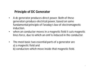
- 1. Principle of DC Generator • A dc generator produces direct power. Both of these generators produce electrical power, based on same fundamental principle of Faraday’s law of electromagnetic induction. • when an conductor moves in a magnetic field it cuts magnetic lines force, due to which an emf is induced in the conductor. • The most basic two essential parts of a generator are a) a magnetic field and b) conductors which move inside that magnetic field. 1
- 2. Single Loop DC Generator Rectangular loop of conductor is ABCD which rotates inside the magnetic field about its won axis ab. As during this movement two sides, i.e. AB and CD of the loop cut the flux lines there will be an emf induced in these both of the sides 2
- 3. The loop is opened and connect it with a split ring as shown in the figure below. Single Loop DC Generator 3
- 4. It is seen that in the first half of the revolution current flows always along ABLMCD i.e. brush no 1 in contact with segment a. In the next half revolution, in the figure the direction of the induced current in the coil is reversed. But at the same time the position of the segments a and b are also reversed which results that brush no 1 comes in touch with that segment b. Hence, the current in the load resistance again flows from L to M. Single Loop DC Generator 4
- 5. The position of the brushes is so arranged that the change over of the segments a and b from one brush to other takes place when the plane of rotating coil is at right angle to the plane of the lines of force. Single Loop DC Generator 5
- 6. Construction of DC Generator A DC Generator has the following parts 1) Yoke 2) Pole of Generator 3) field winding 4) Armature of dc generator 5) Brushes of generator 6) Bearing 6
- 7. Yoke of DC Generator (i) It holds the magnetic pole cores of the generator and acts as cover of the generator. (ii) It carries the magnetic field flux. • In small generator, yoke are made of cast iron. • But for large construction of DC generator, where weight of the machine is concerned, lighter cast steel or rolled steel is preferable for constructing yoke of dc generator. 7
- 8. Pole cores and pole shoes of DC Generator There are mainly two types of construction available. One: Solid pole core, where it made of a solid single piece of cast iron or cast steel. Two: Laminated pole core, where it made of numbers of thin, plates of annealed steel. The construction of magnetic poles basically comprises of two parts namely, the pole core and the pole shoe, stacked together and then attached to the yoke. 8
- 9. These two structures are assigned for different purposes, the pole core is of small cross sectional area and its function is to just hold the pole shoe over the yoke, whereas the pole shoe having a relatively larger cross-sectional area spreads the flux produced over the air gap Pole cores and pole shoes of DC Generator 9
- 10. Armature Core of DC Generator • The purpose of armature core is to hold the armature winding and provide low reluctance path for the flux • Although a dc generator provides direct current but induced current in the armature is alternating in nature. • That is why, cylindrical or drum shaped armature core is build up of circular laminated sheet. • In every circular lamination, slots are either die – cut or punched on the outer periphery and the key way is located on the inner periphery 10
- 11. Armature Winding of DC Generator • Armature winding are generally formed wound. • Various conductors of the coils are insulated from each other. • The conductors are placed in the armature slots, which are lined with tough insulating material. 11
- 12. Commutator of DC Generator • The commutator plays a vital role in dc generator. • It collects current from armature and sends it to the load as direct current. • It actually takes alternating current from armature and converts it to direct current and then send it to external load. • It is cylindrical structured and is build up of wedge – shaped segments of high conductivity, hard drawn or drop forged copper. • Each segment is insulated from the shaft 12
- 13. Brushes of DC Generator • The brushes are made of carbon. • These are rectangular block shaped. • The only function of these carbon brushes of dc generator is to collect current from commutator segments. • The brushes are housed in the rectangular box shaped brush holder. 13
- 14. • If the airgap is of uniform length, the e.m.f. generated in a conductor remains constant while it is moving under a pole face, • and then decreases rapidly to zero when the conductor is midway between the pole tips of adjacent poles. DC generator 14
- 15. • Three coils, 1–1′, 2–2′ and 3–3′, are arranged in the slots so that their end connections overlap one another • we find that the direction of the e.m.f. generated in conductor 1 is towards the paper whereas that generated in conductor 1′ is outwards from the paper. • The distance between coil sides 1 and 1′ is called a pole pitch. • In practice, the coil span must be a whole number and is approximately equal to DC generator 15
- 16. Armature windings can be divided into two groups, depending upon the manner in which the wires are joined to the commutator, namely: 1. Lap windings. 2. Wave windings. • In lap windings the two ends of any one coil are taken to adjacent segments • In wave windings the two ends of each coil are bent in opposite directions and taken to segments some distance apart • if a machine has p pairs of poles • No. of parallel paths with a lap winding = 2p • and No. of parallel paths with a wave winding = 2 Armature winding 16
- 18. • When an armature is rotated through one revolution, each conductor cuts the magnetic flux emanating from all the N poles and also that entering all the S poles. • if Φ is the useful flux per pole, in webers, entering or leaving the armature, p the number of pairs of poles and Nr the speed in revolutions per minute Calculation of e.m.f. generated in an armature winding 18
- 19. Calculation of e.m.f. generated in an armature winding 19
- 20. If Z is the total number of armature conductors, and c the number of parallel paths through winding between positive and negative brushes The number of conductors in series in each of the parallel paths between the brushes remains practically constant; hence total e.m.f. between brushes is Average e.m.f. per conductor × no. of conductors in series per path Calculation of e.m.f. generated in an armature winding 20
- 21. A four-pole wave-connected armature has 51 slots with 12 conductors per slot and is driven at 900 r/min. If the useful flux per pole is 25 mWb, calculate the value of the generated e.m.f. 21
- 22. Total number of conductors = Z = 51 × 12 = 612; c = 2; p = 2; N = 900 r/min; Φ=0.025 Wb Using expression , we have 22
- 23. An eight-pole armature is wound with 480 conductors. The magnetic flux and the speed are such that the average e.m.f. generated in each conductor is 2.2 V, and each conductor is capable of carrying a full-load current of 100 A. Calculate the terminal voltage on no load, the output current on full load and the total power generated on full load when the armature is (a) lap-connected; (b) wave-connected. 23
- 24. 24
- 25. 25
- 26. Copper Losses • Copper loss is the power lost as heat in the windings; it is caused by the flow of current through the coils of the DC armature or DC field. • This loss varies directly with the square of the current in the armature or field and the resistance of the armature or field coils. Armature: Ia 2 Ra Field: If 2 Rf aaaa aaa RIIEP RIEV 2 0 26
- 27. Armature reaction shows the distribution of flux when there is no armature current, the flux in the gap being practically radial and uniformly distributed. shows the distribution of the flux set up by current flowing through the armature winding shows the resultant distribution of the flux due to the combination of the fluxes 27
- 28. • Over the trailing halves of the pole faces the cross flux is in opposition to the main flux, thereby reducing the flux density, whereas over the leading halves the two fluxes are in the same direction, so that the flux density is strengthened. • One important consequence of this distortion of the flux is that the magnetic neutral axis is shifted through an angle θ from AB to CD Armature reaction 28