SlideShare ist ein Scribd-Unternehmen logo
1 von 5
Downloaden Sie, um offline zu lesen
Jitendra Badole et al. Int. Journal of Engineering Research and Application ww.ijera.com
Vol. 3, Issue 5, Sep-Oct 2013, pp.124-128
www.ijera.com 124 | P a g e
Design and Optimization of Microstreap Patch Antenna
for Ultra High Frequency(UHF) Band
Jitendra Badole*, Prof. Rajesh Nema**,
Puran Gour***
*(M Tech Scholar, NIIST, Bhopal, M.P., INDIA)
*(Department Of Electronics and Communication, NIIST Bhopal, INDIA)
** (Department Of Electronics and Communication, NIIST Bhopal, INDIA)
Abstract : Microstrip patch antenna is versatile and vast field of antenna theory. A particular aspect of work
done in this field is presented. In addition a different antenna configuration that improves electrical
performance and sustainability is described. We analyzed microstrip antenna in IE3D by finite moment of
method. In this paper a rectangular microstrip patch antenna with a ground plane is proposed. The antenna is
resonant at 1 GHz frequency. The FR-4 substrate with Dielectric constant 4.3 and loss tangent 0.019 is used
for proposed design at resonant frequency of 1GHz. Radiation characteristics, gain and return loss of the
proposed antenna is simulated using Zeland IE3D simulation software.
General Terms :- Rectangular microstrip patch antenna, Ground plane
Keywords :- Microstrip patch antenna, gain, directivity, IE3D Simulator, Dielectric substrate, return loss.
I. INTRODUCTION
Microstrip patch antenna consists of a
dielectric substrate which has a radiating patch on
one side of the dielectric which has a ground plane
on the other side. Microstrip patch antenna radiates
because of the fringing fields along the edges of the
patch. Microstrip patch antennas have several well-
known advantages such as light weight, low
volume, low profile planar configurations and ease
of fabrication and can be easily integrated.
However, intricate feeding mechanisms to meet the
suitable phase delays make the antenna system
complicated and also cause signal loss.
In this paper we have analyzed Rectangular
geometry and tried to find out at which feed point
better directivity and efficiency can be obtained.
For our detected feed points we have checked out
all the remaining parameters such as dB and phase
of S parameter, VSWR, Smith chart, radiation
pattern, band width, total radiated power and
average radiated power. The structure is showing
good results in terms of gain and directivity. Its
return losses are also of acceptable level.
Fig.1. Rectangular micro strip patch
antenna
II. EFFECTIVE PARAMETER
The principal purpose of antenna is to
shield the antenna and associated equipment from
environment. This improves the availability since
the antenna is not affected by wind, rain or ice.
Typical applications include antennas for radar,
telemetry, tracking, cellular communications,
surveillance, and radio astronomy.
A dielectric or ferrite coating on the surface of
antenna can alter the electromagnetic characteristic,
provide electrical insulation and protect the antenna
from environment. Some ferrite and dielectric
ceramic coating can allow certain antenna design to
reduce in size or height while providing acceptable
radiation characteristic.
The geometry and configuration of praised
antenna is
shown in Figure 1.The antenna consists of a slot on
the ground plane and via holes connecting the
rectangular patch and the microstrip feed-line. All
RESEARCH ARTICLE OPEN ACCESS
Jitendra Badole et al. Int. Journal of Engineering Research and Application ww.ijera.com
Vol. 3, Issue 5, Sep-Oct 2013, pp.124-128
www.ijera.com 125 | P a g e
of these are mounted on a square substrate of a
thickness of 1.5 mm and a relative permittivity of
4.3 with length and width of 71.07568 mm and
92.144 mm respectively.
The effective parameters which define the required
geometries effective length and breadth of
rectangular patch.
Theoretical analysis and calculation of a single
microstrip patch is calculated with following
equations.
The first step is to find the width of rectangular
patch.
Width of rectangular patch is given by:
Where C is speed of light=3*10^11 mm,
fo is resonant frequency=1Ghz
& εr is Dielectric constant of the substrate=4.3
Effective dielectric constant is given by:
Change in length is given by:
Where, h is the height of the substrate. εeff,
effective dielectric constant
Effective length is given by:
Where, εeff is the effective dielectric constant of
the substrate. To measure for the fringing effects,
the actual length of the patch also includes the
correction factor due to fringing effect
Actual length is given by:
Taking FR-4 substrate with Dielectric constant εr
4.3 and loss tangent 0.019 is used for proposed
design at resonant frequency (fo) of 1 GHz. the
above parameters comes out to be W = 92.144 mm,
εr eff = 4.4539, ΔL = 0.6941 mm, Leff = 71.07568
mm, L = 69.6874 mm.
Ground patch of the geometry is design with the
following equations:
Length of ground patch, Lg = 6h+Leff
Width of ground patch, Wg = 6h+W
Lg = 80.07568 mm
Wg= 101.144 mm
Table 1. Antenna Design parameters:
Antenna parameters Dimensions
Resonant frequency fo 1 GHz
Dielectric constant εr 4.3
Height of Substrate (h) 1.5 mm
Width (W) 92.144 mm
Length (L) 71.07568 mm
Effective dielectric
substrate εr eff
4.4539
Width of ground patch
Wg
101.144 mm
Length of ground patch
Lg
80.7568 mm
III.PROPOSED ANTENNA DESIGN
Fig.2. Geometry of proposed single patch array
Antenna
IV .SIMULATED MICROSTRIP
RECTANGULAR PATCH ANTENNA
DESIGN AND RESULTS
The proposed geometry of microstrip
antenna designed with IE3D and simulation is
performed . At the resonant frequency of 1GHz the
design is simulated in the frequency range of 0 to
0.6GHz. The radiation pattern is bidirectional. The
Jitendra Badole et al. Int. Journal of Engineering Research and Application ww.ijera.com
Vol. 3, Issue 5, Sep-Oct 2013, pp.124-128
www.ijera.com 126 | P a g e
simulated results, return losses versus frequency for
geometry shown in fig.4.We are getting better
return loss at four different frequency are -25.88dB
at .1224 GHz , -25.83dB at .2204 GHz,-20.56dB at
.4653 GHz and -18.55dB at .551GHz and The
frequency bands for these with return losses(below
-10dB) of the proposed antenna are:
a) 0.01GHz to 0.159 GHz
b) 0.16GHz to 0.365 GHz
c) 0.454GHz to 0.477 GHz
d) 0.538GHz to 0.56 GHz
The simulated return losses versus frequency
graph shown in fig.4. The Impedance matching is
shown in smith chart is shown in fig.6, its shows
proper impedance matching, VSWR is near about 1
as shown on fig.3.
(1) VSWR VS FREQUENCY
VSWR IS effective and minimum between 0 to 0.6
GHz
Fig.3. VSWR Vs Frequency (in GHz)
For proposed design the value of VSWR is effective between
0GHz to 0.35GHz, for this value return loss is minimum. At
0.1224 GHz return loss is -25.88dB and VSWR is 1.107, which
is minimum value.
(2) RETURN LOSS VS FREQUENCY (IN GHz)
At frequency of 0.1224 GHz the value of return
loss is -25.88 dB
Fig . 4. Retrun loss vs Frequency (in GHz)
(3) S PARAMETER (magnitude in dB and
phase) VS FREQUENCY (IN GHz)
Fig.5.S Parameters Vs Frequency (in GHz)
(4) SMITH CHART
Jitendra Badole et al. Int. Journal of Engineering Research and Application ww.ijera.com
Vol. 3, Issue 5, Sep-Oct 2013, pp.124-128
www.ijera.com 127 | P a g e
Fig.6. Smith Chart
(5) DIRECTIVITY VS FREQUENCY (IN GHz)
Fig.7. Directivity Vs Frequency (in GHz)
(6) RADIATION PATTERN:
Fig.8. Radiation Pattern
(7) 3D PATTERN OF THE ANTENNA
Fig.9. 3D Pattern
V.SIMULATION TABLE
Sn. Frequency (in
GHz)
Return loss
(in dB)
VSWR
1 0.01224 -10.68 1.826
2 0.02449 -14.44 1.468
3 0.03673 -15.27 1.417
4 0.04898 -11.79 1.693
5 0.06122 -13.69 1.522
6 0.07347 -12.13 1.657
7 0.8571 -11.76 1.697
8 0.09796 -12.92 1.584
9 0.1102 -15.25 1.418
10 0.1224 -25.88 1.107
11 0.1347 -16.17 1.368
12 0.1469 -10.69 1.825
Jitendra Badole et al. Int. Journal of Engineering Research and Application ww.ijera.com
Vol. 3, Issue 5, Sep-Oct 2013, pp.124-128
www.ijera.com 128 | P a g e
13 0.1592 -9.827 1.952
14 0.1714 -13.27 1.554
15 0.1837 -20.88 1.199
16 0.1959 -17.32 1.315
17 0.2082 -16.69 1.343
18 0.2204 -25.83 1.108
19 0.2327 -20.23 1.26
20 0.2449 -17.5 1.308
21 0.2571 -16.51 1.352
22 0.2694 -18.28 1.278
23 0.2816 -17.34 1.314
24 0.2939 -12.06 1.665
25 0.3061 -10.56 1.842
26 0.3184 -13.04 1.573
27 0.3306 -16.8 1.338
28 0.3429 -12.97 1.58
29 0.3551 -11.1 1.772
30 0.3673 -9.278 2.047
31 0.3796 -5.927 3.044
32 0.3918 -5.169 3.459
33 0.4041 -5.697 3.158
34 0.4163 -5.687 3.163
35 0.4286 -4.965 3.594
36 0.4408 -5.509 3.258
37 0.4531 -9.683 1.976
38 0.4653 -20.56 1.207
39 0.4776 -9.479 3.011
40 0.4898 -5.998 3.01
41 0.502 -4.529 3.922
42 0.5143 -4.514 3.934
43 0.5265 -5.844 3.084
44 0.5388 -10.5 1.852
45 0.551 -18.155 1.268
46 0.5633 -8.063 2.307
47 0.5755 -4.177 4.239
48 0.5878 -2.923 6
49 0.6 -2.926 5.993
CONCLUTION
A novel antenna with via holes at UHF is
illustrated in this paper. It consists of a ground
plane, a rectangular microstrip patch slot and a via
hole connecting the rectangular patch and the
microstrip feed-line. The better return losses are
due to the slots cut in the rectangular patch and by
connecting via hole. The antenna is resonant at
1GHz frequency and simulated up to 0.6GHz. The
return loss obtained is -25.88 dBi at .1224 GHz
VSWR is 1.107, which is minimum value. . The
return losses at four frequency bands are -25.88dB
at .1224 GHz , -25.83dB at .2204 GHz,-20.56dB at
.4653 GHz and -18.55dB at 0.551GHz and The
frequency bands for these with return losses(below
-10dB) of the proposed antenna are:
a) 0.01GHz to 0.159 GHz
b) 0.16GHz to 0.365 GHz
c) 0.454GHz to 0.477 GHz
d) 0.538GHz to 0.56 GHz
This antenna is very easy to fabricate and
implement in any circuit and also of low cost as this
structure is not complicated. The antenna is
successfully designed, constructed, and measured.
ACKNOWLEDGEMENT
The author of this paper are thankful for the
director of the NRI Institute of Information Science
and Technology, Bhopal for making the simulation
tool IE3D available for designing and simulation of
the proposed antenna. The author is also thankful
for Mr. Rajesh Nema H.O.D. of Electronics &
Communication,Mr. Puran Gour(Assoc. Prof. of
EC Dept.) and Mr. Rajeev Thakur(Assoc. Prof. of
EC Dept.) of the same institute who encouraged me
tremendously during the designing process and also
during the literature review.
REFERENCES
[1] Jun Zhang, Yunliang Long, Senior
Member, IEEE “A Dual-layer Broadband
Compact UHF RFID Tag Antenna for
Platform Tolerant Application “2013
[2] Balanis C.A(1982) Handbook of Microstrip
Antennas. John Wiley and Sons New York
[3] New Multiband E-Shape Microstrip Patch
Antenna On RT DUROID 5880 Substrate
and RO4003 Substrate for Pervasive
Wireless Communication. Dr. Anubhuti
Khare, Rajesh Nema and Puran Gour
[4] Bojana Zivanovic, Thomas M. Weller , and
Carlos Coatas “Series-Fed Microstrip
Antenna Array and Their Applications to
Omni-Directional Antenna ”, IEEE Trans.
AntennaPropag., Vol.60,No.10. pp.4954-
4959,October 2012
[5] Experimental Investigation of an
Equilateral Triangular Microstrip Antenna
with a Dielectric Radome. Manotosh
Biswas and Debatosh Guha, Institute of
Radio Physics and Electronics, University
of Calcutta, Kolkata (India). International
Conference on Microwave – 08.
[6] Qing-Xin Chu, Member, IEEE, and Ying-
Ying Yang, “A Compact Ultra wideband
Antenna With 3.4/5.5 GHz Dual Band-
Notched Characteristics”, IEEE
Transactions on Antennas And Propagation,
Vol. 56, No. 12, December 2008.
[7] G. Kumar and K.P. Ray, ” Broadband
Microstrip Antennas”, Artech House, 2003.

Weitere ähnliche Inhalte

Was ist angesagt?

Miniaturized Microstrip Patch Antenna Array at 3.8 GHz for WiMax Application
Miniaturized Microstrip Patch Antenna Array at 3.8 GHz for WiMax ApplicationMiniaturized Microstrip Patch Antenna Array at 3.8 GHz for WiMax Application
Miniaturized Microstrip Patch Antenna Array at 3.8 GHz for WiMax Applicationiosrjce
 
An Improved Bandwidth for Electromagnetic Gap Coupled Rhombus Shaped Microstr...
An Improved Bandwidth for Electromagnetic Gap Coupled Rhombus Shaped Microstr...An Improved Bandwidth for Electromagnetic Gap Coupled Rhombus Shaped Microstr...
An Improved Bandwidth for Electromagnetic Gap Coupled Rhombus Shaped Microstr...IJERA Editor
 
Parametric Variation Based Analysis AND Effective Design of Rectangular Patch...
Parametric Variation Based Analysis AND Effective Design of Rectangular Patch...Parametric Variation Based Analysis AND Effective Design of Rectangular Patch...
Parametric Variation Based Analysis AND Effective Design of Rectangular Patch...IOSR Journals
 
A New Design of Dual-Band Microstrip Patch Antenna for Wireless Communication
A New Design of Dual-Band Microstrip Patch Antenna for Wireless CommunicationA New Design of Dual-Band Microstrip Patch Antenna for Wireless Communication
A New Design of Dual-Band Microstrip Patch Antenna for Wireless CommunicationIRJET Journal
 
Dv31587594
Dv31587594Dv31587594
Dv31587594IJMER
 
Varactor diode loaded double square reconfigurable microstrip patch ante
Varactor diode loaded double square reconfigurable microstrip patch anteVaractor diode loaded double square reconfigurable microstrip patch ante
Varactor diode loaded double square reconfigurable microstrip patch anteIAEME Publication
 
Numerical parametric study on interval shift variation in simo sstd technique...
Numerical parametric study on interval shift variation in simo sstd technique...Numerical parametric study on interval shift variation in simo sstd technique...
Numerical parametric study on interval shift variation in simo sstd technique...eSAT Journals
 
International Journal of Computational Engineering Research(IJCER)
International Journal of Computational Engineering Research(IJCER)International Journal of Computational Engineering Research(IJCER)
International Journal of Computational Engineering Research(IJCER)ijceronline
 
BODY ANTENNA WITH DGS FOR BODY CENTRIC WIRELESS COMMUNICATION SYSTEM
BODY ANTENNA WITH DGS FOR BODY CENTRIC WIRELESS COMMUNICATION SYSTEMBODY ANTENNA WITH DGS FOR BODY CENTRIC WIRELESS COMMUNICATION SYSTEM
BODY ANTENNA WITH DGS FOR BODY CENTRIC WIRELESS COMMUNICATION SYSTEMjantjournal
 

Was ist angesagt? (13)

Miniaturized Microstrip Patch Antenna Array at 3.8 GHz for WiMax Application
Miniaturized Microstrip Patch Antenna Array at 3.8 GHz for WiMax ApplicationMiniaturized Microstrip Patch Antenna Array at 3.8 GHz for WiMax Application
Miniaturized Microstrip Patch Antenna Array at 3.8 GHz for WiMax Application
 
An Improved Bandwidth for Electromagnetic Gap Coupled Rhombus Shaped Microstr...
An Improved Bandwidth for Electromagnetic Gap Coupled Rhombus Shaped Microstr...An Improved Bandwidth for Electromagnetic Gap Coupled Rhombus Shaped Microstr...
An Improved Bandwidth for Electromagnetic Gap Coupled Rhombus Shaped Microstr...
 
Parametric Variation Based Analysis AND Effective Design of Rectangular Patch...
Parametric Variation Based Analysis AND Effective Design of Rectangular Patch...Parametric Variation Based Analysis AND Effective Design of Rectangular Patch...
Parametric Variation Based Analysis AND Effective Design of Rectangular Patch...
 
A New Design of Dual-Band Microstrip Patch Antenna for Wireless Communication
A New Design of Dual-Band Microstrip Patch Antenna for Wireless CommunicationA New Design of Dual-Band Microstrip Patch Antenna for Wireless Communication
A New Design of Dual-Band Microstrip Patch Antenna for Wireless Communication
 
Dv31587594
Dv31587594Dv31587594
Dv31587594
 
Varactor diode loaded double square reconfigurable microstrip patch ante
Varactor diode loaded double square reconfigurable microstrip patch anteVaractor diode loaded double square reconfigurable microstrip patch ante
Varactor diode loaded double square reconfigurable microstrip patch ante
 
J010316368
J010316368J010316368
J010316368
 
C010311421
C010311421C010311421
C010311421
 
40120140501019
4012014050101940120140501019
40120140501019
 
Numerical parametric study on interval shift variation in simo sstd technique...
Numerical parametric study on interval shift variation in simo sstd technique...Numerical parametric study on interval shift variation in simo sstd technique...
Numerical parametric study on interval shift variation in simo sstd technique...
 
Es4301871876
Es4301871876Es4301871876
Es4301871876
 
International Journal of Computational Engineering Research(IJCER)
International Journal of Computational Engineering Research(IJCER)International Journal of Computational Engineering Research(IJCER)
International Journal of Computational Engineering Research(IJCER)
 
BODY ANTENNA WITH DGS FOR BODY CENTRIC WIRELESS COMMUNICATION SYSTEM
BODY ANTENNA WITH DGS FOR BODY CENTRIC WIRELESS COMMUNICATION SYSTEMBODY ANTENNA WITH DGS FOR BODY CENTRIC WIRELESS COMMUNICATION SYSTEM
BODY ANTENNA WITH DGS FOR BODY CENTRIC WIRELESS COMMUNICATION SYSTEM
 

Andere mochten auch (20)

Z35149151
Z35149151Z35149151
Z35149151
 
Pd3426592664
Pd3426592664Pd3426592664
Pd3426592664
 
Oc3424632467
Oc3424632467Oc3424632467
Oc3424632467
 
Q358895
Q358895Q358895
Q358895
 
Pe3426652670
Pe3426652670Pe3426652670
Pe3426652670
 
Ot3425662590
Ot3425662590Ot3425662590
Ot3425662590
 
Oq3425482554
Oq3425482554Oq3425482554
Oq3425482554
 
Oa3424532456
Oa3424532456Oa3424532456
Oa3424532456
 
Ch33509513
Ch33509513Ch33509513
Ch33509513
 
Ci33514517
Ci33514517Ci33514517
Ci33514517
 
Cn33543547
Cn33543547Cn33543547
Cn33543547
 
Uwb antenna by debashish(IIT DELHI)
Uwb antenna by debashish(IIT DELHI)Uwb antenna by debashish(IIT DELHI)
Uwb antenna by debashish(IIT DELHI)
 
UWB patch antenna (HFSS)
UWB patch antenna (HFSS)UWB patch antenna (HFSS)
UWB patch antenna (HFSS)
 
Novel Microstrip Antenna Design for UWB
Novel Microstrip Antenna Design for UWBNovel Microstrip Antenna Design for UWB
Novel Microstrip Antenna Design for UWB
 
Ppt
PptPpt
Ppt
 
Sistemas mecanicos
Sistemas mecanicosSistemas mecanicos
Sistemas mecanicos
 
Ensayo 1
Ensayo 1Ensayo 1
Ensayo 1
 
Web 2
Web 2Web 2
Web 2
 
Svako Č počinje s Čakovcem
Svako Č počinje s ČakovcemSvako Č počinje s Čakovcem
Svako Č počinje s Čakovcem
 
Projetos 2007 b
Projetos 2007   bProjetos 2007   b
Projetos 2007 b
 

Ähnlich wie W35124128

Paper id 27201432
Paper id 27201432Paper id 27201432
Paper id 27201432IJRAT
 
Study On The Improvement Of Bandwidth Of A Rectangular Microstrip Patch Antenna
Study On The Improvement Of Bandwidth Of A Rectangular Microstrip Patch AntennaStudy On The Improvement Of Bandwidth Of A Rectangular Microstrip Patch Antenna
Study On The Improvement Of Bandwidth Of A Rectangular Microstrip Patch AntennaIOSR Journals
 
Circular Slot Loaded Rectangular Microstrip Patch Antenna For WLAN / WiMax Ap...
Circular Slot Loaded Rectangular Microstrip Patch Antenna For WLAN / WiMax Ap...Circular Slot Loaded Rectangular Microstrip Patch Antenna For WLAN / WiMax Ap...
Circular Slot Loaded Rectangular Microstrip Patch Antenna For WLAN / WiMax Ap...IJSRD
 
DESIGN OF A MINIATURE RECTANGULAR PATCH ANTENNA FOR KU BAND APPLICATIONS
DESIGN OF A MINIATURE RECTANGULAR PATCH ANTENNA FOR KU BAND APPLICATIONSDESIGN OF A MINIATURE RECTANGULAR PATCH ANTENNA FOR KU BAND APPLICATIONS
DESIGN OF A MINIATURE RECTANGULAR PATCH ANTENNA FOR KU BAND APPLICATIONSijasa
 
BODY ANTENNA WITH DGS FOR BODY CENTRIC WIRELESS COMMUNICATION SYSTEM
BODY ANTENNA WITH DGS FOR BODY CENTRIC WIRELESS COMMUNICATION SYSTEMBODY ANTENNA WITH DGS FOR BODY CENTRIC WIRELESS COMMUNICATION SYSTEM
BODY ANTENNA WITH DGS FOR BODY CENTRIC WIRELESS COMMUNICATION SYSTEMjantjournal
 
BODY ANTENNA WITH DGS FOR BODY CENTRIC WIRELESS COMMUNICATION SYSTEM
BODY ANTENNA WITH DGS FOR BODY CENTRIC WIRELESS COMMUNICATION SYSTEMBODY ANTENNA WITH DGS FOR BODY CENTRIC WIRELESS COMMUNICATION SYSTEM
BODY ANTENNA WITH DGS FOR BODY CENTRIC WIRELESS COMMUNICATION SYSTEMjantjournal
 
BODY ANTENNA WITH DGS FOR BODY CENTRIC WIRELESS COMMUNICATION SYSTEM
BODY ANTENNA WITH DGS FOR BODY CENTRIC WIRELESS COMMUNICATION SYSTEMBODY ANTENNA WITH DGS FOR BODY CENTRIC WIRELESS COMMUNICATION SYSTEM
BODY ANTENNA WITH DGS FOR BODY CENTRIC WIRELESS COMMUNICATION SYSTEMjantjournal
 
Ijarcet vol-2-issue-7-2302-2306
Ijarcet vol-2-issue-7-2302-2306Ijarcet vol-2-issue-7-2302-2306
Ijarcet vol-2-issue-7-2302-2306Editor IJARCET
 
BODY ANTENNA WITH DGS FOR BODY CENTRIC WIRELESS COMMUNICATION SYSTEM
BODY ANTENNA WITH DGS FOR BODY CENTRIC WIRELESS COMMUNICATION SYSTEMBODY ANTENNA WITH DGS FOR BODY CENTRIC WIRELESS COMMUNICATION SYSTEM
BODY ANTENNA WITH DGS FOR BODY CENTRIC WIRELESS COMMUNICATION SYSTEMjantjournal
 
BODY ANTENNA WITH DGS FOR BODY CENTRIC WIRELESS COMMUNICATION SYSTEM
BODY ANTENNA WITH DGS FOR BODY CENTRIC WIRELESS COMMUNICATION SYSTEMBODY ANTENNA WITH DGS FOR BODY CENTRIC WIRELESS COMMUNICATION SYSTEM
BODY ANTENNA WITH DGS FOR BODY CENTRIC WIRELESS COMMUNICATION SYSTEMjantjournal
 
BODY ANTENNA WITH DGS FOR BODY CENTRIC WIRELESS COMMUNICATION SYSTEM
BODY ANTENNA WITH DGS FOR BODY CENTRIC WIRELESS COMMUNICATION SYSTEMBODY ANTENNA WITH DGS FOR BODY CENTRIC WIRELESS COMMUNICATION SYSTEM
BODY ANTENNA WITH DGS FOR BODY CENTRIC WIRELESS COMMUNICATION SYSTEMjantjournal
 
DESIGN & PARAMETRIC STUDY OF RECTANGULAR SLOT MICROSTRIP PATCH ANTENNA FOR UW...
DESIGN & PARAMETRIC STUDY OF RECTANGULAR SLOT MICROSTRIP PATCH ANTENNA FOR UW...DESIGN & PARAMETRIC STUDY OF RECTANGULAR SLOT MICROSTRIP PATCH ANTENNA FOR UW...
DESIGN & PARAMETRIC STUDY OF RECTANGULAR SLOT MICROSTRIP PATCH ANTENNA FOR UW...IJEEE
 
BODY ANTENNA WITH DGS FOR BODY CENTRIC WIRELESS COMMUNICATION SYSTEM
BODY ANTENNA WITH DGS FOR BODY CENTRIC WIRELESS COMMUNICATION SYSTEMBODY ANTENNA WITH DGS FOR BODY CENTRIC WIRELESS COMMUNICATION SYSTEM
BODY ANTENNA WITH DGS FOR BODY CENTRIC WIRELESS COMMUNICATION SYSTEMjantjournal
 
BODY ANTENNA WITH DGS FOR BODY CENTRIC WIRELESS COMMUNICATION SYSTEM
BODY ANTENNA WITH DGS FOR BODY CENTRIC WIRELESS COMMUNICATION SYSTEMBODY ANTENNA WITH DGS FOR BODY CENTRIC WIRELESS COMMUNICATION SYSTEM
BODY ANTENNA WITH DGS FOR BODY CENTRIC WIRELESS COMMUNICATION SYSTEMjantjournal
 
BODY ANTENNA WITH DGS FOR BODY CENTRIC WIRELESS COMMUNICATION SYSTEM
BODY ANTENNA WITH DGS FOR BODY CENTRIC WIRELESS COMMUNICATION SYSTEMBODY ANTENNA WITH DGS FOR BODY CENTRIC WIRELESS COMMUNICATION SYSTEM
BODY ANTENNA WITH DGS FOR BODY CENTRIC WIRELESS COMMUNICATION SYSTEMjantjournal
 

Ähnlich wie W35124128 (20)

A42040104
A42040104A42040104
A42040104
 
Paper id 27201432
Paper id 27201432Paper id 27201432
Paper id 27201432
 
Study On The Improvement Of Bandwidth Of A Rectangular Microstrip Patch Antenna
Study On The Improvement Of Bandwidth Of A Rectangular Microstrip Patch AntennaStudy On The Improvement Of Bandwidth Of A Rectangular Microstrip Patch Antenna
Study On The Improvement Of Bandwidth Of A Rectangular Microstrip Patch Antenna
 
Study On The Improvement Of Bandwidth Of A Rectangular Microstrip Patch Antenna
Study On The Improvement Of Bandwidth Of A Rectangular Microstrip Patch AntennaStudy On The Improvement Of Bandwidth Of A Rectangular Microstrip Patch Antenna
Study On The Improvement Of Bandwidth Of A Rectangular Microstrip Patch Antenna
 
M45027282
M45027282M45027282
M45027282
 
Circular Slot Loaded Rectangular Microstrip Patch Antenna For WLAN / WiMax Ap...
Circular Slot Loaded Rectangular Microstrip Patch Antenna For WLAN / WiMax Ap...Circular Slot Loaded Rectangular Microstrip Patch Antenna For WLAN / WiMax Ap...
Circular Slot Loaded Rectangular Microstrip Patch Antenna For WLAN / WiMax Ap...
 
DESIGN OF A MINIATURE RECTANGULAR PATCH ANTENNA FOR KU BAND APPLICATIONS
DESIGN OF A MINIATURE RECTANGULAR PATCH ANTENNA FOR KU BAND APPLICATIONSDESIGN OF A MINIATURE RECTANGULAR PATCH ANTENNA FOR KU BAND APPLICATIONS
DESIGN OF A MINIATURE RECTANGULAR PATCH ANTENNA FOR KU BAND APPLICATIONS
 
BODY ANTENNA WITH DGS FOR BODY CENTRIC WIRELESS COMMUNICATION SYSTEM
BODY ANTENNA WITH DGS FOR BODY CENTRIC WIRELESS COMMUNICATION SYSTEMBODY ANTENNA WITH DGS FOR BODY CENTRIC WIRELESS COMMUNICATION SYSTEM
BODY ANTENNA WITH DGS FOR BODY CENTRIC WIRELESS COMMUNICATION SYSTEM
 
BODY ANTENNA WITH DGS FOR BODY CENTRIC WIRELESS COMMUNICATION SYSTEM
BODY ANTENNA WITH DGS FOR BODY CENTRIC WIRELESS COMMUNICATION SYSTEMBODY ANTENNA WITH DGS FOR BODY CENTRIC WIRELESS COMMUNICATION SYSTEM
BODY ANTENNA WITH DGS FOR BODY CENTRIC WIRELESS COMMUNICATION SYSTEM
 
BODY ANTENNA WITH DGS FOR BODY CENTRIC WIRELESS COMMUNICATION SYSTEM
BODY ANTENNA WITH DGS FOR BODY CENTRIC WIRELESS COMMUNICATION SYSTEMBODY ANTENNA WITH DGS FOR BODY CENTRIC WIRELESS COMMUNICATION SYSTEM
BODY ANTENNA WITH DGS FOR BODY CENTRIC WIRELESS COMMUNICATION SYSTEM
 
Ijarcet vol-2-issue-7-2302-2306
Ijarcet vol-2-issue-7-2302-2306Ijarcet vol-2-issue-7-2302-2306
Ijarcet vol-2-issue-7-2302-2306
 
Fp35996999
Fp35996999Fp35996999
Fp35996999
 
BODY ANTENNA WITH DGS FOR BODY CENTRIC WIRELESS COMMUNICATION SYSTEM
BODY ANTENNA WITH DGS FOR BODY CENTRIC WIRELESS COMMUNICATION SYSTEMBODY ANTENNA WITH DGS FOR BODY CENTRIC WIRELESS COMMUNICATION SYSTEM
BODY ANTENNA WITH DGS FOR BODY CENTRIC WIRELESS COMMUNICATION SYSTEM
 
BODY ANTENNA WITH DGS FOR BODY CENTRIC WIRELESS COMMUNICATION SYSTEM
BODY ANTENNA WITH DGS FOR BODY CENTRIC WIRELESS COMMUNICATION SYSTEMBODY ANTENNA WITH DGS FOR BODY CENTRIC WIRELESS COMMUNICATION SYSTEM
BODY ANTENNA WITH DGS FOR BODY CENTRIC WIRELESS COMMUNICATION SYSTEM
 
BODY ANTENNA WITH DGS FOR BODY CENTRIC WIRELESS COMMUNICATION SYSTEM
BODY ANTENNA WITH DGS FOR BODY CENTRIC WIRELESS COMMUNICATION SYSTEMBODY ANTENNA WITH DGS FOR BODY CENTRIC WIRELESS COMMUNICATION SYSTEM
BODY ANTENNA WITH DGS FOR BODY CENTRIC WIRELESS COMMUNICATION SYSTEM
 
DESIGN & PARAMETRIC STUDY OF RECTANGULAR SLOT MICROSTRIP PATCH ANTENNA FOR UW...
DESIGN & PARAMETRIC STUDY OF RECTANGULAR SLOT MICROSTRIP PATCH ANTENNA FOR UW...DESIGN & PARAMETRIC STUDY OF RECTANGULAR SLOT MICROSTRIP PATCH ANTENNA FOR UW...
DESIGN & PARAMETRIC STUDY OF RECTANGULAR SLOT MICROSTRIP PATCH ANTENNA FOR UW...
 
P010227680
P010227680P010227680
P010227680
 
BODY ANTENNA WITH DGS FOR BODY CENTRIC WIRELESS COMMUNICATION SYSTEM
BODY ANTENNA WITH DGS FOR BODY CENTRIC WIRELESS COMMUNICATION SYSTEMBODY ANTENNA WITH DGS FOR BODY CENTRIC WIRELESS COMMUNICATION SYSTEM
BODY ANTENNA WITH DGS FOR BODY CENTRIC WIRELESS COMMUNICATION SYSTEM
 
BODY ANTENNA WITH DGS FOR BODY CENTRIC WIRELESS COMMUNICATION SYSTEM
BODY ANTENNA WITH DGS FOR BODY CENTRIC WIRELESS COMMUNICATION SYSTEMBODY ANTENNA WITH DGS FOR BODY CENTRIC WIRELESS COMMUNICATION SYSTEM
BODY ANTENNA WITH DGS FOR BODY CENTRIC WIRELESS COMMUNICATION SYSTEM
 
BODY ANTENNA WITH DGS FOR BODY CENTRIC WIRELESS COMMUNICATION SYSTEM
BODY ANTENNA WITH DGS FOR BODY CENTRIC WIRELESS COMMUNICATION SYSTEMBODY ANTENNA WITH DGS FOR BODY CENTRIC WIRELESS COMMUNICATION SYSTEM
BODY ANTENNA WITH DGS FOR BODY CENTRIC WIRELESS COMMUNICATION SYSTEM
 

Kürzlich hochgeladen

From Event to Action: Accelerate Your Decision Making with Real-Time Automation
From Event to Action: Accelerate Your Decision Making with Real-Time AutomationFrom Event to Action: Accelerate Your Decision Making with Real-Time Automation
From Event to Action: Accelerate Your Decision Making with Real-Time AutomationSafe Software
 
GenCyber Cyber Security Day Presentation
GenCyber Cyber Security Day PresentationGenCyber Cyber Security Day Presentation
GenCyber Cyber Security Day PresentationMichael W. Hawkins
 
08448380779 Call Girls In Greater Kailash - I Women Seeking Men
08448380779 Call Girls In Greater Kailash - I Women Seeking Men08448380779 Call Girls In Greater Kailash - I Women Seeking Men
08448380779 Call Girls In Greater Kailash - I Women Seeking MenDelhi Call girls
 
Transcript: #StandardsGoals for 2024: What’s new for BISAC - Tech Forum 2024
Transcript: #StandardsGoals for 2024: What’s new for BISAC - Tech Forum 2024Transcript: #StandardsGoals for 2024: What’s new for BISAC - Tech Forum 2024
Transcript: #StandardsGoals for 2024: What’s new for BISAC - Tech Forum 2024BookNet Canada
 
Slack Application Development 101 Slides
Slack Application Development 101 SlidesSlack Application Development 101 Slides
Slack Application Development 101 Slidespraypatel2
 
Breaking the Kubernetes Kill Chain: Host Path Mount
Breaking the Kubernetes Kill Chain: Host Path MountBreaking the Kubernetes Kill Chain: Host Path Mount
Breaking the Kubernetes Kill Chain: Host Path MountPuma Security, LLC
 
How to convert PDF to text with Nanonets
How to convert PDF to text with NanonetsHow to convert PDF to text with Nanonets
How to convert PDF to text with Nanonetsnaman860154
 
Raspberry Pi 5: Challenges and Solutions in Bringing up an OpenGL/Vulkan Driv...
Raspberry Pi 5: Challenges and Solutions in Bringing up an OpenGL/Vulkan Driv...Raspberry Pi 5: Challenges and Solutions in Bringing up an OpenGL/Vulkan Driv...
Raspberry Pi 5: Challenges and Solutions in Bringing up an OpenGL/Vulkan Driv...Igalia
 
Scaling API-first – The story of a global engineering organization
Scaling API-first – The story of a global engineering organizationScaling API-first – The story of a global engineering organization
Scaling API-first – The story of a global engineering organizationRadu Cotescu
 
Automating Business Process via MuleSoft Composer | Bangalore MuleSoft Meetup...
Automating Business Process via MuleSoft Composer | Bangalore MuleSoft Meetup...Automating Business Process via MuleSoft Composer | Bangalore MuleSoft Meetup...
Automating Business Process via MuleSoft Composer | Bangalore MuleSoft Meetup...shyamraj55
 
Strategies for Unlocking Knowledge Management in Microsoft 365 in the Copilot...
Strategies for Unlocking Knowledge Management in Microsoft 365 in the Copilot...Strategies for Unlocking Knowledge Management in Microsoft 365 in the Copilot...
Strategies for Unlocking Knowledge Management in Microsoft 365 in the Copilot...Drew Madelung
 
Maximizing Board Effectiveness 2024 Webinar.pptx
Maximizing Board Effectiveness 2024 Webinar.pptxMaximizing Board Effectiveness 2024 Webinar.pptx
Maximizing Board Effectiveness 2024 Webinar.pptxOnBoard
 
Mastering MySQL Database Architecture: Deep Dive into MySQL Shell and MySQL R...
Mastering MySQL Database Architecture: Deep Dive into MySQL Shell and MySQL R...Mastering MySQL Database Architecture: Deep Dive into MySQL Shell and MySQL R...
Mastering MySQL Database Architecture: Deep Dive into MySQL Shell and MySQL R...Miguel Araújo
 
Handwritten Text Recognition for manuscripts and early printed texts
Handwritten Text Recognition for manuscripts and early printed textsHandwritten Text Recognition for manuscripts and early printed texts
Handwritten Text Recognition for manuscripts and early printed textsMaria Levchenko
 
Kalyanpur ) Call Girls in Lucknow Finest Escorts Service 🍸 8923113531 🎰 Avail...
Kalyanpur ) Call Girls in Lucknow Finest Escorts Service 🍸 8923113531 🎰 Avail...Kalyanpur ) Call Girls in Lucknow Finest Escorts Service 🍸 8923113531 🎰 Avail...
Kalyanpur ) Call Girls in Lucknow Finest Escorts Service 🍸 8923113531 🎰 Avail...gurkirankumar98700
 
Neo4j - How KGs are shaping the future of Generative AI at AWS Summit London ...
Neo4j - How KGs are shaping the future of Generative AI at AWS Summit London ...Neo4j - How KGs are shaping the future of Generative AI at AWS Summit London ...
Neo4j - How KGs are shaping the future of Generative AI at AWS Summit London ...Neo4j
 
My Hashitalk Indonesia April 2024 Presentation
My Hashitalk Indonesia April 2024 PresentationMy Hashitalk Indonesia April 2024 Presentation
My Hashitalk Indonesia April 2024 PresentationRidwan Fadjar
 
SQL Database Design For Developers at php[tek] 2024
SQL Database Design For Developers at php[tek] 2024SQL Database Design For Developers at php[tek] 2024
SQL Database Design For Developers at php[tek] 2024Scott Keck-Warren
 
🐬 The future of MySQL is Postgres 🐘
🐬  The future of MySQL is Postgres   🐘🐬  The future of MySQL is Postgres   🐘
🐬 The future of MySQL is Postgres 🐘RTylerCroy
 
How to Troubleshoot Apps for the Modern Connected Worker
How to Troubleshoot Apps for the Modern Connected WorkerHow to Troubleshoot Apps for the Modern Connected Worker
How to Troubleshoot Apps for the Modern Connected WorkerThousandEyes
 

Kürzlich hochgeladen (20)

From Event to Action: Accelerate Your Decision Making with Real-Time Automation
From Event to Action: Accelerate Your Decision Making with Real-Time AutomationFrom Event to Action: Accelerate Your Decision Making with Real-Time Automation
From Event to Action: Accelerate Your Decision Making with Real-Time Automation
 
GenCyber Cyber Security Day Presentation
GenCyber Cyber Security Day PresentationGenCyber Cyber Security Day Presentation
GenCyber Cyber Security Day Presentation
 
08448380779 Call Girls In Greater Kailash - I Women Seeking Men
08448380779 Call Girls In Greater Kailash - I Women Seeking Men08448380779 Call Girls In Greater Kailash - I Women Seeking Men
08448380779 Call Girls In Greater Kailash - I Women Seeking Men
 
Transcript: #StandardsGoals for 2024: What’s new for BISAC - Tech Forum 2024
Transcript: #StandardsGoals for 2024: What’s new for BISAC - Tech Forum 2024Transcript: #StandardsGoals for 2024: What’s new for BISAC - Tech Forum 2024
Transcript: #StandardsGoals for 2024: What’s new for BISAC - Tech Forum 2024
 
Slack Application Development 101 Slides
Slack Application Development 101 SlidesSlack Application Development 101 Slides
Slack Application Development 101 Slides
 
Breaking the Kubernetes Kill Chain: Host Path Mount
Breaking the Kubernetes Kill Chain: Host Path MountBreaking the Kubernetes Kill Chain: Host Path Mount
Breaking the Kubernetes Kill Chain: Host Path Mount
 
How to convert PDF to text with Nanonets
How to convert PDF to text with NanonetsHow to convert PDF to text with Nanonets
How to convert PDF to text with Nanonets
 
Raspberry Pi 5: Challenges and Solutions in Bringing up an OpenGL/Vulkan Driv...
Raspberry Pi 5: Challenges and Solutions in Bringing up an OpenGL/Vulkan Driv...Raspberry Pi 5: Challenges and Solutions in Bringing up an OpenGL/Vulkan Driv...
Raspberry Pi 5: Challenges and Solutions in Bringing up an OpenGL/Vulkan Driv...
 
Scaling API-first – The story of a global engineering organization
Scaling API-first – The story of a global engineering organizationScaling API-first – The story of a global engineering organization
Scaling API-first – The story of a global engineering organization
 
Automating Business Process via MuleSoft Composer | Bangalore MuleSoft Meetup...
Automating Business Process via MuleSoft Composer | Bangalore MuleSoft Meetup...Automating Business Process via MuleSoft Composer | Bangalore MuleSoft Meetup...
Automating Business Process via MuleSoft Composer | Bangalore MuleSoft Meetup...
 
Strategies for Unlocking Knowledge Management in Microsoft 365 in the Copilot...
Strategies for Unlocking Knowledge Management in Microsoft 365 in the Copilot...Strategies for Unlocking Knowledge Management in Microsoft 365 in the Copilot...
Strategies for Unlocking Knowledge Management in Microsoft 365 in the Copilot...
 
Maximizing Board Effectiveness 2024 Webinar.pptx
Maximizing Board Effectiveness 2024 Webinar.pptxMaximizing Board Effectiveness 2024 Webinar.pptx
Maximizing Board Effectiveness 2024 Webinar.pptx
 
Mastering MySQL Database Architecture: Deep Dive into MySQL Shell and MySQL R...
Mastering MySQL Database Architecture: Deep Dive into MySQL Shell and MySQL R...Mastering MySQL Database Architecture: Deep Dive into MySQL Shell and MySQL R...
Mastering MySQL Database Architecture: Deep Dive into MySQL Shell and MySQL R...
 
Handwritten Text Recognition for manuscripts and early printed texts
Handwritten Text Recognition for manuscripts and early printed textsHandwritten Text Recognition for manuscripts and early printed texts
Handwritten Text Recognition for manuscripts and early printed texts
 
Kalyanpur ) Call Girls in Lucknow Finest Escorts Service 🍸 8923113531 🎰 Avail...
Kalyanpur ) Call Girls in Lucknow Finest Escorts Service 🍸 8923113531 🎰 Avail...Kalyanpur ) Call Girls in Lucknow Finest Escorts Service 🍸 8923113531 🎰 Avail...
Kalyanpur ) Call Girls in Lucknow Finest Escorts Service 🍸 8923113531 🎰 Avail...
 
Neo4j - How KGs are shaping the future of Generative AI at AWS Summit London ...
Neo4j - How KGs are shaping the future of Generative AI at AWS Summit London ...Neo4j - How KGs are shaping the future of Generative AI at AWS Summit London ...
Neo4j - How KGs are shaping the future of Generative AI at AWS Summit London ...
 
My Hashitalk Indonesia April 2024 Presentation
My Hashitalk Indonesia April 2024 PresentationMy Hashitalk Indonesia April 2024 Presentation
My Hashitalk Indonesia April 2024 Presentation
 
SQL Database Design For Developers at php[tek] 2024
SQL Database Design For Developers at php[tek] 2024SQL Database Design For Developers at php[tek] 2024
SQL Database Design For Developers at php[tek] 2024
 
🐬 The future of MySQL is Postgres 🐘
🐬  The future of MySQL is Postgres   🐘🐬  The future of MySQL is Postgres   🐘
🐬 The future of MySQL is Postgres 🐘
 
How to Troubleshoot Apps for the Modern Connected Worker
How to Troubleshoot Apps for the Modern Connected WorkerHow to Troubleshoot Apps for the Modern Connected Worker
How to Troubleshoot Apps for the Modern Connected Worker
 

W35124128

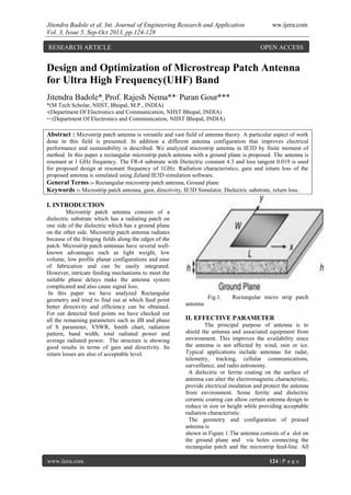
  • 1. Jitendra Badole et al. Int. Journal of Engineering Research and Application ww.ijera.com Vol. 3, Issue 5, Sep-Oct 2013, pp.124-128 www.ijera.com 124 | P a g e Design and Optimization of Microstreap Patch Antenna for Ultra High Frequency(UHF) Band Jitendra Badole*, Prof. Rajesh Nema**, Puran Gour*** *(M Tech Scholar, NIIST, Bhopal, M.P., INDIA) *(Department Of Electronics and Communication, NIIST Bhopal, INDIA) ** (Department Of Electronics and Communication, NIIST Bhopal, INDIA) Abstract : Microstrip patch antenna is versatile and vast field of antenna theory. A particular aspect of work done in this field is presented. In addition a different antenna configuration that improves electrical performance and sustainability is described. We analyzed microstrip antenna in IE3D by finite moment of method. In this paper a rectangular microstrip patch antenna with a ground plane is proposed. The antenna is resonant at 1 GHz frequency. The FR-4 substrate with Dielectric constant 4.3 and loss tangent 0.019 is used for proposed design at resonant frequency of 1GHz. Radiation characteristics, gain and return loss of the proposed antenna is simulated using Zeland IE3D simulation software. General Terms :- Rectangular microstrip patch antenna, Ground plane Keywords :- Microstrip patch antenna, gain, directivity, IE3D Simulator, Dielectric substrate, return loss. I. INTRODUCTION Microstrip patch antenna consists of a dielectric substrate which has a radiating patch on one side of the dielectric which has a ground plane on the other side. Microstrip patch antenna radiates because of the fringing fields along the edges of the patch. Microstrip patch antennas have several well- known advantages such as light weight, low volume, low profile planar configurations and ease of fabrication and can be easily integrated. However, intricate feeding mechanisms to meet the suitable phase delays make the antenna system complicated and also cause signal loss. In this paper we have analyzed Rectangular geometry and tried to find out at which feed point better directivity and efficiency can be obtained. For our detected feed points we have checked out all the remaining parameters such as dB and phase of S parameter, VSWR, Smith chart, radiation pattern, band width, total radiated power and average radiated power. The structure is showing good results in terms of gain and directivity. Its return losses are also of acceptable level. Fig.1. Rectangular micro strip patch antenna II. EFFECTIVE PARAMETER The principal purpose of antenna is to shield the antenna and associated equipment from environment. This improves the availability since the antenna is not affected by wind, rain or ice. Typical applications include antennas for radar, telemetry, tracking, cellular communications, surveillance, and radio astronomy. A dielectric or ferrite coating on the surface of antenna can alter the electromagnetic characteristic, provide electrical insulation and protect the antenna from environment. Some ferrite and dielectric ceramic coating can allow certain antenna design to reduce in size or height while providing acceptable radiation characteristic. The geometry and configuration of praised antenna is shown in Figure 1.The antenna consists of a slot on the ground plane and via holes connecting the rectangular patch and the microstrip feed-line. All RESEARCH ARTICLE OPEN ACCESS
  • 2. Jitendra Badole et al. Int. Journal of Engineering Research and Application ww.ijera.com Vol. 3, Issue 5, Sep-Oct 2013, pp.124-128 www.ijera.com 125 | P a g e of these are mounted on a square substrate of a thickness of 1.5 mm and a relative permittivity of 4.3 with length and width of 71.07568 mm and 92.144 mm respectively. The effective parameters which define the required geometries effective length and breadth of rectangular patch. Theoretical analysis and calculation of a single microstrip patch is calculated with following equations. The first step is to find the width of rectangular patch. Width of rectangular patch is given by: Where C is speed of light=3*10^11 mm, fo is resonant frequency=1Ghz & εr is Dielectric constant of the substrate=4.3 Effective dielectric constant is given by: Change in length is given by: Where, h is the height of the substrate. εeff, effective dielectric constant Effective length is given by: Where, εeff is the effective dielectric constant of the substrate. To measure for the fringing effects, the actual length of the patch also includes the correction factor due to fringing effect Actual length is given by: Taking FR-4 substrate with Dielectric constant εr 4.3 and loss tangent 0.019 is used for proposed design at resonant frequency (fo) of 1 GHz. the above parameters comes out to be W = 92.144 mm, εr eff = 4.4539, ΔL = 0.6941 mm, Leff = 71.07568 mm, L = 69.6874 mm. Ground patch of the geometry is design with the following equations: Length of ground patch, Lg = 6h+Leff Width of ground patch, Wg = 6h+W Lg = 80.07568 mm Wg= 101.144 mm Table 1. Antenna Design parameters: Antenna parameters Dimensions Resonant frequency fo 1 GHz Dielectric constant εr 4.3 Height of Substrate (h) 1.5 mm Width (W) 92.144 mm Length (L) 71.07568 mm Effective dielectric substrate εr eff 4.4539 Width of ground patch Wg 101.144 mm Length of ground patch Lg 80.7568 mm III.PROPOSED ANTENNA DESIGN Fig.2. Geometry of proposed single patch array Antenna IV .SIMULATED MICROSTRIP RECTANGULAR PATCH ANTENNA DESIGN AND RESULTS The proposed geometry of microstrip antenna designed with IE3D and simulation is performed . At the resonant frequency of 1GHz the design is simulated in the frequency range of 0 to 0.6GHz. The radiation pattern is bidirectional. The
  • 3. Jitendra Badole et al. Int. Journal of Engineering Research and Application ww.ijera.com Vol. 3, Issue 5, Sep-Oct 2013, pp.124-128 www.ijera.com 126 | P a g e simulated results, return losses versus frequency for geometry shown in fig.4.We are getting better return loss at four different frequency are -25.88dB at .1224 GHz , -25.83dB at .2204 GHz,-20.56dB at .4653 GHz and -18.55dB at .551GHz and The frequency bands for these with return losses(below -10dB) of the proposed antenna are: a) 0.01GHz to 0.159 GHz b) 0.16GHz to 0.365 GHz c) 0.454GHz to 0.477 GHz d) 0.538GHz to 0.56 GHz The simulated return losses versus frequency graph shown in fig.4. The Impedance matching is shown in smith chart is shown in fig.6, its shows proper impedance matching, VSWR is near about 1 as shown on fig.3. (1) VSWR VS FREQUENCY VSWR IS effective and minimum between 0 to 0.6 GHz Fig.3. VSWR Vs Frequency (in GHz) For proposed design the value of VSWR is effective between 0GHz to 0.35GHz, for this value return loss is minimum. At 0.1224 GHz return loss is -25.88dB and VSWR is 1.107, which is minimum value. (2) RETURN LOSS VS FREQUENCY (IN GHz) At frequency of 0.1224 GHz the value of return loss is -25.88 dB Fig . 4. Retrun loss vs Frequency (in GHz) (3) S PARAMETER (magnitude in dB and phase) VS FREQUENCY (IN GHz) Fig.5.S Parameters Vs Frequency (in GHz) (4) SMITH CHART
  • 4. Jitendra Badole et al. Int. Journal of Engineering Research and Application ww.ijera.com Vol. 3, Issue 5, Sep-Oct 2013, pp.124-128 www.ijera.com 127 | P a g e Fig.6. Smith Chart (5) DIRECTIVITY VS FREQUENCY (IN GHz) Fig.7. Directivity Vs Frequency (in GHz) (6) RADIATION PATTERN: Fig.8. Radiation Pattern (7) 3D PATTERN OF THE ANTENNA Fig.9. 3D Pattern V.SIMULATION TABLE Sn. Frequency (in GHz) Return loss (in dB) VSWR 1 0.01224 -10.68 1.826 2 0.02449 -14.44 1.468 3 0.03673 -15.27 1.417 4 0.04898 -11.79 1.693 5 0.06122 -13.69 1.522 6 0.07347 -12.13 1.657 7 0.8571 -11.76 1.697 8 0.09796 -12.92 1.584 9 0.1102 -15.25 1.418 10 0.1224 -25.88 1.107 11 0.1347 -16.17 1.368 12 0.1469 -10.69 1.825
  • 5. Jitendra Badole et al. Int. Journal of Engineering Research and Application ww.ijera.com Vol. 3, Issue 5, Sep-Oct 2013, pp.124-128 www.ijera.com 128 | P a g e 13 0.1592 -9.827 1.952 14 0.1714 -13.27 1.554 15 0.1837 -20.88 1.199 16 0.1959 -17.32 1.315 17 0.2082 -16.69 1.343 18 0.2204 -25.83 1.108 19 0.2327 -20.23 1.26 20 0.2449 -17.5 1.308 21 0.2571 -16.51 1.352 22 0.2694 -18.28 1.278 23 0.2816 -17.34 1.314 24 0.2939 -12.06 1.665 25 0.3061 -10.56 1.842 26 0.3184 -13.04 1.573 27 0.3306 -16.8 1.338 28 0.3429 -12.97 1.58 29 0.3551 -11.1 1.772 30 0.3673 -9.278 2.047 31 0.3796 -5.927 3.044 32 0.3918 -5.169 3.459 33 0.4041 -5.697 3.158 34 0.4163 -5.687 3.163 35 0.4286 -4.965 3.594 36 0.4408 -5.509 3.258 37 0.4531 -9.683 1.976 38 0.4653 -20.56 1.207 39 0.4776 -9.479 3.011 40 0.4898 -5.998 3.01 41 0.502 -4.529 3.922 42 0.5143 -4.514 3.934 43 0.5265 -5.844 3.084 44 0.5388 -10.5 1.852 45 0.551 -18.155 1.268 46 0.5633 -8.063 2.307 47 0.5755 -4.177 4.239 48 0.5878 -2.923 6 49 0.6 -2.926 5.993 CONCLUTION A novel antenna with via holes at UHF is illustrated in this paper. It consists of a ground plane, a rectangular microstrip patch slot and a via hole connecting the rectangular patch and the microstrip feed-line. The better return losses are due to the slots cut in the rectangular patch and by connecting via hole. The antenna is resonant at 1GHz frequency and simulated up to 0.6GHz. The return loss obtained is -25.88 dBi at .1224 GHz VSWR is 1.107, which is minimum value. . The return losses at four frequency bands are -25.88dB at .1224 GHz , -25.83dB at .2204 GHz,-20.56dB at .4653 GHz and -18.55dB at 0.551GHz and The frequency bands for these with return losses(below -10dB) of the proposed antenna are: a) 0.01GHz to 0.159 GHz b) 0.16GHz to 0.365 GHz c) 0.454GHz to 0.477 GHz d) 0.538GHz to 0.56 GHz This antenna is very easy to fabricate and implement in any circuit and also of low cost as this structure is not complicated. The antenna is successfully designed, constructed, and measured. ACKNOWLEDGEMENT The author of this paper are thankful for the director of the NRI Institute of Information Science and Technology, Bhopal for making the simulation tool IE3D available for designing and simulation of the proposed antenna. The author is also thankful for Mr. Rajesh Nema H.O.D. of Electronics & Communication,Mr. Puran Gour(Assoc. Prof. of EC Dept.) and Mr. Rajeev Thakur(Assoc. Prof. of EC Dept.) of the same institute who encouraged me tremendously during the designing process and also during the literature review. REFERENCES [1] Jun Zhang, Yunliang Long, Senior Member, IEEE “A Dual-layer Broadband Compact UHF RFID Tag Antenna for Platform Tolerant Application “2013 [2] Balanis C.A(1982) Handbook of Microstrip Antennas. John Wiley and Sons New York [3] New Multiband E-Shape Microstrip Patch Antenna On RT DUROID 5880 Substrate and RO4003 Substrate for Pervasive Wireless Communication. Dr. Anubhuti Khare, Rajesh Nema and Puran Gour [4] Bojana Zivanovic, Thomas M. Weller , and Carlos Coatas “Series-Fed Microstrip Antenna Array and Their Applications to Omni-Directional Antenna ”, IEEE Trans. AntennaPropag., Vol.60,No.10. pp.4954- 4959,October 2012 [5] Experimental Investigation of an Equilateral Triangular Microstrip Antenna with a Dielectric Radome. Manotosh Biswas and Debatosh Guha, Institute of Radio Physics and Electronics, University of Calcutta, Kolkata (India). International Conference on Microwave – 08. [6] Qing-Xin Chu, Member, IEEE, and Ying- Ying Yang, “A Compact Ultra wideband Antenna With 3.4/5.5 GHz Dual Band- Notched Characteristics”, IEEE Transactions on Antennas And Propagation, Vol. 56, No. 12, December 2008. [7] G. Kumar and K.P. Ray, ” Broadband Microstrip Antennas”, Artech House, 2003.