Weitere ähnliche Inhalte
Ähnlich wie Factors Affecting Bending Stress in Asymmetric Spur Gears
Ähnlich wie Factors Affecting Bending Stress in Asymmetric Spur Gears (20)
Mehr von IAEME Publication
Mehr von IAEME Publication (20)
Kürzlich hochgeladen (20)
Factors Affecting Bending Stress in Asymmetric Spur Gears
- 1. International Journal of Mechanical Engineering and Technology (IJMET), ISSN 0976 –
6340(Print), ISSN 0976 – 6359(Online) Volume 4, Issue 4, July - August (2013) © IAEME
266
FACTOR AFFECTING THE BENDING STRESS AT CRITICAL SECTION
OF ASYMMETRIC SPUR GEAR
Dr J M Prajapati1
, P A Vaghela2
1
Department of Mechanical Engineering,
Faculty of Technology & Engineering, Baroda, Gujarat, India
2
Department of Mechanical Engineering,
Government Polytechnic, Vadnagar, Gujarat, India
ABSTRACT
The main objective of this review paper is to show how the different parameters are affecting
the bending stress at critical section of asymmetric spur gear. Bending stress at critical section is
most important parameter in gear design. It must be low as low possible. Our try to minimize it by
optimize all affected Parameters of asymmetric spur gear tooth to reduce Bending Stress at critical
section of tooth. This reduction can translate into Increased Load Capacity, Size and Weight
Reduction, Longer Life, Cost Reduction, Increased Reliability, Noise and Vibration reduction,
Increased Gear Efficiency and Maintenance Cost Reduction etc.
As the pressure angle on drive side increases, the bending stress reduces at critical section of
asymmetric spur gear. But Decision on maximum magnitude of drive side pressure angle is
constraint by the safe contact ratio and tooth peaking effect. These way parameters are affecting
directly or indirectly on performance. There are so many parameters are likes Contact ratio, Top land
tip thickness, Pressure angle on drive side profile, Pressure angle on coast side profile, Asymmetry
factor, No. of teeth, Interference, Undercut, Centre distance, Gear ratio, Critical section thickness,
Profile shift of pinion, Profile shift of gear, Module, Bending stress at critical section, Optimal fillet
radius and Balance stress etc. affects the performance. So, it is necessarily to optimize these affected
Parameters of asymmetric spur gear tooth to reduce Bending Stress at critical section of tooth.
Key words: Asymmetric spur gear tooth, parameters, critical section thickness.
INTRODUCTION
Gears are the most common means of transmitting power in the modern mechanical
engineering world. A gear can be defined as a machine element used to transmit motion and power
between rotating shafts by means of progressive engagement of projections called teeth. Gears have
a wide variety of applications which vary from a tiny size used in watches to the large gears used in
INTERNATIONAL JOURNAL OF MECHANICAL ENGINEERING
AND TECHNOLOGY (IJMET)
ISSN 0976 – 6340 (Print)
ISSN 0976 – 6359 (Online)
Volume 4, Issue 4, July - August (2013), pp. 266-273
© IAEME: www.iaeme.com/ijmet.asp
Journal Impact Factor (2013): 5.7731 (Calculated by GISI)
www.jifactor.com
IJMET
© I A E M E
- 2. International Journal of Mechanical Engineering and Technology (IJMET), ISSN 0976 –
6340(Print), ISSN 0976 – 6359(Online) Volume 4, Issue 4, July - August (2013) © IAEME
267
lifting mechanisms and speed reducers. They form vital elements of main and ancillary mechanisms
in many machines such as automobiles, tractors, metal cutting machine tools etc.
In recent times, the gear design has become a highly complicated and comprehensive subject.
A designer of a modern gear drive system must remember that the main objective of a gear drive is
to transmit higher power with comparatively smaller overall dimensions of the driving system which
can be constructed with the minimum possible manufacturing cost, runs reasonably free of noise and
vibration, and which required little maintenance. It has to satisfy, among others the above conditions
and design accordingly, so that the design is sound as well as economically viable.
The two profiles (sides) of a gear tooth are functionally different for many gears. The
workload on one profile is significantly higher and is applied for longer periods of time than for the
opposite one. The design of the asymmetric tooth shape reflects this functional difference.
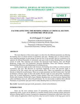
Fig. 1: Asymmetric spur gear.
An asymmetric spur gear drive means that larger and smaller pressure angles are applied for
the driving and coast sides. The two profiles of a gear tooth are functionally different for most gear
drives. The workload on one side of profile is significantly higher than the other Gears.
Fig. 2: Asymmetric spur gear with different base circles.
The design intent of asymmetric gear teeth is to improve the performance of the primary
contacting profile. The opposite profile is typically unloaded or lightly loaded during relatively short
work periods. The degree of asymmetry and drive profile selection for these gears depends on the
application.
The difference between symmetric and asymmetric tooth is defined by two involutes of two
different base circles Dbd and Dbc. The common base tooth thickness does not exist in the
asymmetric tooth. The circular distance (tooth thickness) Sp between involute profiles is defined at
some reference circle diameter Dp that should be bigger than the largest base diameter.
- 3. International Journal of Mechanical Engineering and Technology (IJMET), ISSN 0976 –
6340(Print), ISSN 0976 – 6359(Online) Volume 4, Issue 4, July - August (2013) © IAEME
268
LITERATURE SURVEY
Kapelevich has developed a method for design of gears with asymmetric teeth. It is found
that direct gear design procedure for the synthesis of asymmetric gear pair using an area of existence
method and designed the rack cutter parameters to generate these desired asymmetric gear tooth
profiles. It is found that asymmetric tooth geometry (with larger pressure angle on drive tooth side)
allow for an increase in load capacity while reducing weight and dimensions for same types of
gears.[1] Litvin et al. have proposed a modified geometry of asymmetric gear pair as a combination
of an involute gear and a double crowned gear. The contact and bending stresses for the driving side
(with a larger pressure angle) of an asymmetric spur gear drive are reduced. Modified geometry of
asymmetric spur gears for reduction of transmission errors and localization of bearing contact.[2]
Alexander L. Kapelevich and Yuriy V. Shekhtman found Optimization of the fillet profile allows
reducing the maximum bending stress in the gear tooth root area by 10–30%. It works equally well
for both symmetric and asymmetric gear tooth profiles. This bending stress reduction can be traded
for Size and weight reduction, longer life, higher load application, Cost reduction (less expensive
materials, heat treatment, etc.), lower noise and vibration. [3] Alexander L. Kapelevich and Thomas
M. McNamara also observe Direct Gear Design results in 15-30% reduction in stress level when
compared to traditionally designed gears. This reduction can be translated into Increased Load
Capacity (15-30%) , Size and Weight Reduction (10-20%), Longer Life, Cost Reduction, Increased
Reliability , Noise and Vibration Reduction (finer pitch, more teeth will result in higher contact ratio
for the given center distance), Increased Gear Efficiency (1-2% per stage),Maintenance Cost
Reduction and Other benefits Depending on the Application.Direct gear design for asymmetric tooth
profiles provides additional opportunity for improvement of gear drives with unidirectional load
cycles that are typical for many mechanical transmissions.[4] V. Senthil Kumar et al.have observed
With this choice of design, the full optimization with respect to bending stress is not found. The
positive effect on the bending stress is then solely related to a root thickness increase of the tooth, but
the stress can be further reduced using shape optimization to reduce the stress concentration.The
influence of several non-standard asymmetric rack cutters are designed to accommodate different
combinations in the values of pressure angle, top land thickness ratio, profile shift, speed ratio and
the asymmetric factors on the maximum fillet stress has been analyzed to suggest the optimum
values of these parameters that improve the fillet capacity in bending.[5] Singh Vedang et al. found
As the pressure angle on drive side increases, the bending stress decreases and bending load capacity
increases. Decision on maximum magnitude of drive side pressure angle is constraint by the safe
contact ratio and tooth peaking effect.[6] Alexander L. Kapelevich has developed Direct Gear
Design is an alternative approach to traditional gear design. It is not constrained by predefined
tooling parameters. It allows for the analysis of a wide range of parameters for all possible gear
combinations in order to find the most suitable solution for a particular custom application. This gear
design method can exceed the limits of traditional rack generating methods of gear design.
Direct Gear Design results in a 15-30% reduction in stress level when compared to
traditionally designed gears. This reduction can be translated into Increased Load Capacity (15-30%)
, Size and Weight Reduction (10-20%), Longer Life, Cost Reduction, Increased Reliability, Noise
and Vibration reduction , Increased Gear Efficiency and Maintenance Cost Reduction.[7] Th.
Costopoulos, V. Spitas et al. have In this paper the concept of the asymmetric one-sided -involute
gear teeth was introduced and studied using FEA. Due to this concept increase load carrying capacity
and combine the good meshing properties of the driving involute and the increased strength of non
involute curves.The geometry of the proposed gears was investigated and the generation process was
modeled using the Theory of Gearing. The novel design incorporates two main innovative features,
which are the substitution of the standard trochoidal fillet with a circular fillet for the reduction of the
stress concentration at the driving side and the use of a fully rack or hob-generated, addendum
geometry for the coast side. The increase in load carrying capacity can reach up to 28% compared to
- 4. International Journal of Mechanical Engineering and Technology (IJMET), ISSN 0976 –
6340(Print), ISSN 0976 – 6359(Online) Volume 4, Issue 4, July - August (2013) © IAEME
269
the standard 20_ involute teeth.[8] Niels L. Pedersen was investigated In the papers on asymmetric
tooth design there seems to be two choices: either αd<αc, i.e., the drive side pressure angle is smaller
than the coast side pressure angle or αd>αc. The choice made is αd>αc is stated that this choice is
made because it reduces the mesh stiffness that has a positive influence on noise and vibration levels.
The choice made is αd<αc and here it is shown that this only has a little influence on the mesh
stiffness. The present paper does not discuss mesh stiffness and both choices of relative pressure
angles are shown in the examples in order to explore the possible advantages. When increasing
pressure angles the negative result is that the top land thickness becomes smaller and in the limit it
becomes pointed, with a further increase in the pressure angle the teeth become shorter. A shorter
teeth decrease the contact ratio, which is undesirable. The minimum top land thickness limit is
sa>.25 M, for carburized gears the limit is reported to be higher sa>0.4 M.The largest reduction in
the bending stress can be found with αd>αc. With a drive side pressure angle, αd=36° (AE1), the
bending stress reduction compared to the standard ISO tooth is about 40% independent of the
number of teeth on the gear. Maximum difference as compared to an optimized tooth is 3% and With
a coast side pressure angle, αc=34° (AE2), the bending stress reduction compared to the standard
ISO tooth is about 18% independent of the number of teeth on the gear. Maximum difference as
compared to an optimized tooth is 5%.[9] Moya J.L et al. found a theoretical analysis of a procedure
to determine the Lewis Factor, which can play a major role in the fracture of asymmetric plastic gear
teeth.The Lewis factor for different coefficient of asymmetry is calculated for different number of
teeth and it is found that Lewis factor increases with coefficient of asymmetry and number of
teeth.[10] Alexander Kapelevich and Yuriy Shekhtman presents a unique approach and
methodology to define the limits of selection for gear parameters. The area within those limits is
called the “area of existence of involute gears”. This paper presents the definition and construction of
areas of existence of both external and internal gears. The isograms of the constant operating
pressure angles, contact ratios and the maximum mesh efficiency (minimum sliding) isograms, as
well as the interference isograms and other parameters are defined. An area of existence allows the
location of gear pairs with certain characteristics. Its practical purpose is to define the gear pair
parameters that satisfy specific performance requirements before detailed design and calculations.
An area of existence of gears with asymmetric teeth is also considered.[11] Alex Kapelevich
describes an alternative Direct Gear Design approach for the asymmetric gear design, demonstrating
the basic gear tooth and mesh parameter definition. It also familiarizes with a proprietary tooth fillet
profiles optimization technique, providing minimum bending stress concentration.[12] G. Mallesh et
al. Estimate the critical section for different pressure angles and backup ratios using computer
programme and compare the results obtained by other researchers. Developed programme is used to
create a finite element model for symmetric and asymmetric spur gear tooth to study the effect of
bending stress at the critical section for different backup ratios. The rim thickness was varied and the
location and magnitude of the maximum bending stresses were reported and results obtained were
compared with the Lewis bending equation.[13] G. Mallesh et al. study the effect of bending stress at
the critical section for different pressure angles on the drive side along with the profile shift.
Comparison has been made for symmetric and asymmetric spur gear tooth using Lewis equation and
Finite element analysis software. With the effect of positive shift there is an increase in the tooth
thickness at the critical section. With the effect of positive shift there is a reduction in the bending
stress at the critical section.[14] Dr. Alexander L. Kapelevich presents definitions of main inspection
dimensions and parameters for directly designed spur and helical, external and internal gears with
symmetric and asymmetric teeth.[15] G. Mallesh et al. Generate asymmetric spur gear tooth
geometry for different pressure angles on drive and coast side using computer programme.
Developed programme is used to create a finite element model of gear tooth to study the effect of
bending stress at the critical section for different pressure angles, different number of teeth and
module. To study the effect of above asymmetric spur tooth parameters Finite Element Analysis
software ANSYS was used.As the number of teeth and module increases the bending stresses
- 5. International Journal of Mechanical Engineering and Technology (IJMET), ISSN 0976 –
6340(Print), ISSN 0976 – 6359(Online) Volume 4, Issue 4, July - August (2013) © IAEME
270
decreases, while the other parameters are unchanged. This is due to the fact that with increase of
module, the pitch diameters of the gear tooth increases causing the tooth to become bulkier and
stronger. Again with the increase of module, the fillet radius of the tooth increases which would
cause less impact in the root region (critical section) of the gear tooth. The increase of module means
the increase of the tooth width from top to bottom, as a result the stress is observed to be less in the
wider tooth for the same loading. The bending stresses decreases with increases in the number of
teeth and pressure angle on drive side, with the application of the same load for all gear teeth and one
with more teeth, i.e. the bigger one will be stressed lesser. It is observed that as the pressure angle on
the drive side increases bending stress decreases.[16] A. Kapelevich and Y. Shekhtman found the
gear tooth fillet is an area of maximum bending stress concentration. This paper presents a fillet
profile optimization technique for gears with symmetric and asymmetric teeth based on FEA and a
random search method. It allows achieving substantial bending stress reduction in comparison with
traditionally designed gears. The bending stress reduction provided by the fillet optimization can be
converted into other gear performance benefits, such as contact stress reduction and increased gear
mesh efficiency higher load capacity, longer lifetime, lower noise and vibration and cost
reduction.[17] Konstandinos G. Raptis et al. shows how to calculate highest point of single tooth
contact- HPSTC using both numerical and experimental methods. At this point single pair of gear
teeth is subjected to the total load which is most unfavorable contact point because maximum stress
at gear tooth root are generate.[18] Vaghela P A and Patel D A shows in this paper is to
Improvement of Load Carrying Capacity by increases the pressure angle on drive side profile of
asymmetric spur gear constraint by the safe contact ratio and tooth peaking effect. Bending stress at
the critical section reduces drastically with increases in the pressure angle on the drive side for
certain limit. Load carrying capacity of gear increasing from 2150 N to 3820 N without
compromising a bending stress 41.73 MPa at critical section of spur gear tooth root.[19] Vaghela P A
and Patel D A observed that after the modification by increases the pressure angle on drive side
profile of asymmetric spur gear constraint by the safe contact ratio and tooth peaking effect. Bending
stress at the critical section reduces drastically with increases in the pressure angle on the drive side
for certain limit. Axial thickness is optimized from 40 mm to a 26.25mm without compromising a
bending stress 41.73 MPa at critical section of spur gear tooth root.[20] Vaghela P A and Patel D A
obtain optimal line, on this line point gives optimize value for improvement of load carrying capacity
and reduction in weight without compromising bending stress at critical section of spur gear tooth
root. Bellow this optimal line zone is feasible or safe and above this optimal line zone is not feasible
or unsafe.On this optimal line, left most point on load 2150 N gives only axial thickness reduction
without improvement in load carrying capacity and right most point on load 3820 N gives only
improvement in load carrying capacity without axial thickness reduction. Intermediate point between
these two points gives a partially reduction in axial thickness of gear (weight reduction) and partially
improvements in the load carrying capacity in such a way that it satisfy limit of bending stress not
more than 41.73 MPa at critical section of spur gear tooth root. [21]
CONCLUDED REMARKS
Bending stress at critical section is most important parameter in gear design. It must be low
as low possible. Our try to minimize it by optimize all affected Parameters of asymmetric spur gear
tooth to reduce Bending Stress at critical section of tooth. This reduction can be translated into
Increased Load Capacity (15-30%), Size and Weight Reduction (10-20%), Longer Life, Cost
Reduction, Increased Reliability, Noise and Vibration reduction, Increased Gear Efficiency and
Maintenance Cost Reduction. For custom gear following parameters are affects its performance so it
is necessary to optimizing it. Contact ratio:-As the pressure angle on drive side increases, the
bending stress reduces at critical section of asymmetric spur gear and Decision on maximum
magnitude of drive side pressure angle is constraint by the safe contact ratio and its value is 1.1.
- 6. International Journal of Mechanical Engineering and Technology (IJMET), ISSN 0976 –
6340(Print), ISSN 0976 – 6359(Online) Volume 4, Issue 4, July - August (2013) © IAEME
271
Bellow this value, the loading period of a single gear tooth pair significantly increases, which is
undesirable under cyclic loading conditions. [6, 9, 10, 11, 18]Top land tip thickness: - As the
pressure angle on drive side increases, the bending stress reduces at critical section of asymmetric
spur gear and Decision on maximum magnitude of drive side pressure angle is constraint by the top
land tip thickness and its value is should be greater than equal to 0.2 times the module for the
hardened gears. Bellow this value, tip thickness decreases and tip becomes too sharp, more and more
pointed. [6, 9, 11, 19, 20, 21]Pressure angle on drive side profile: - As the pressure angle on drive
side increases, the bending stress reduces at critical section of asymmetric spur gear. [9, 13, 14,
16]Pressure angle on coast side profile: - As the pressure angle on drive side increases, the bending
stress reduces at critical section of asymmetric spur gear. [9, 13, 14, 16]The largest reduction in the
bending stress can be found with (pressure angle on drive side profile) αd>αc(pressure angle on coast
side profile). Because, With a drive side pressure angle αd=36° the bending stress reduction
compared to the standard ISO tooth is about 40% independent of the number of teeth on the gear and
With a coast side pressure angle, αc=34° the bending stress reduction compared to the standard ISO
tooth is about 18% independent of the number of teeth on the gear. [9]Asymmetry factor: - The
concept of the asymmetry factor was incorporated to cater for asymmetry. It is the relation between
the driving side profile and the coast side profile angles. Asymmetry factor= driving side profile
angle/ coast side profile angles. [10]No. of teeth: - The minimum number of teeth which a pinion
can have to mate with a rack without interference and undercutting can be calculated using
equation.z= 2/sinα^2 If minimum number of teeth condition is not satisfied interference and undercut
problems occurs. As the pressure angle on drive side increases, it allow to reduce the minimum
number of teeth so at critical section the bending stress reduces. [16]Interference :-When the gear
tooth tries to dig below the base circle of mating gear then the gear tooth action shall be non
conjugate and violate the fundamental law of gearing this non conjugate action is called the
interference.[11,14]Undercut: - A condition in generated gear teeth when any part of the fillet curve
lies inside of a line drawn tangent to the working profile at its lowest point. [11,14]Critical section
thickness:-Thickness of the critical section increases with increase in pressure angle, the bending
stress reduces at critical section of asymmetric spur gear as critical section thickness increases. The
gear becomes bigger and having more resistance to the load as critical section thickness increases.
[14]Profile shift of pinion:-With the effect of positive shift there is an increase in the tooth thickness
at the critical section. Increasing the pressure angle, the bending stress at the critical section
decreases for a given profile shift value. With the effect of positive shift there is a decrease in the
bending stress at the critical section. [14]Profile shift of gear:-With the effect of positive shift there
is an increase in the tooth thickness at the critical section. Increasing the pressure angle, the bending
stress at the critical section decreases for a given profile shift value. With the effect of positive shift
there is a decrease in the bending stress at the critical section. [14]Module:-As module increases the
gear becomes bigger and having more resistance to the load. As the module increases the bending
stresses decreases, while the other parameters are unchanged. This is due to the fact that with
increase of module, the pitch diameters of the gear tooth increases causing the tooth to become
bulkier and stronger. Again with the increase of module, the fillet radius of the tooth increases which
would cause less impact in the root region (critical section) of the gear tooth. The increase of module
means the increase of the tooth width from top to bottom, as a result the stress is observed to be less
in the wider tooth for the same loading. Thickness of the critical section increases slightly with
increase in pressure angle, and directly depends on the module. It is the fact that as module increases
the gear becomes bigger and having more resistance to the load. [14, 16]Optimal fillet radius: - It is
also known as a Fillet Profile Optimization. In this our aim is to minimizing bending stress
concentration along the fillet. The gear tooth fillet is an area of maximum bending stress
concentration. A fillet profile optimization technique for gears with asymmetric teeth based on FEA
and a random search method us to minimizing bending stress concentration along the fillet. It allows
achieving substantial bending stress reduction in comparison with traditionally designed gears. [3, 4,
- 7. International Journal of Mechanical Engineering and Technology (IJMET), ISSN 0976 –
6340(Print), ISSN 0976 – 6359(Online) Volume 4, Issue 4, July - August (2013) © IAEME
272
7, 12, 15, 17]Balance stress:-Bending Stress Balance - achieving equally strong gears by adjusting
the tooth thicknesses at the operating pitch diameters. An iteration method combined with FEA is
used. Bending stress balance allows equalizing the tooth strength and durability for the pinion and
the gear. [3, 4, 12]Bending stress at critical section: - Bending stress at critical section is most
important parameter in gear design. It must be low as low possible. Our try to minimize it by
optimize all affected Parameters of asymmetric spur gear tooth to reduce Bending Stress at critical
section of tooth. This reduction can be translated into Increased Load Capacity, Size and Weight
Reduction, Longer Life, Cost Reduction, Increased Reliability, Noise and Vibration reduction,
Increased Gear Efficiency and Maintenance Cost Reduction etc. [1, 2, 5, 8, 9, 17]
So, it is necessarily to optimize these affected Parameters of asymmetric spur gear tooth to
reduce Bending Stress at critical section of tooth.
REFERENCES
PAPERS
[1] Alexander Kapelevich “Geometry and design of involute spur gears with asymmetric teeth”
Mechanism and Machine Theory 35 (2000) 117 to 130
[2] Faydor L. Litvin , Qiming Lian , Alexander L. Kapelevich “Asymmetric modified spur gear
drives: reduction of noise, localization of contact, simulation of meshing and stress analysis”
Computer Methods Applied Mechanics and Engineering. 188 (2000) 363 to 390
[3] Alexander L. Kapelevich and Yuriy V. Shekhtman” Direct Gear Design: Bending Stress
Minimization” GEAR TECHNOLOGY, SEPTEMBER/OCTOBER 2003
[4] Alexander L. Kapelevich and Thomas M. McNamara “ Direct Gear Design for Optimal Gear
Performance” SME's Gear Processing and Manufacturing Clinic, October 6, 2003 held in
conjunction with AGMA's GEAR EXPO '03 in Columbus, OH
[5] V. Senthil Kumar, D.V. Muni, G. Muthuveerappan “Optimization of asymmetric spur gear
drives to improve the bending load capacity” Mechanism and Machine Theory 43 (2008) 829–
858
[6] Singh Vedang and Senthilvelan S., “Computer Aided Design of Asymmetric Gear”, 13th
National Conference on Mechanisms and Machines (NaCoMM07),IISc, Bangalore, India,
December 12-13, 2007
[7] Alexander L. Kapelevich,Thomas M. McNamara (Thermotech Company) “Introduction to
Direct Gear Design”
[8] Th. Costopoulos, V. Spitas “Reduction of gear fillet stresses by using one-sided involute
asymmetric teeth”, Mechanism and Machine Theory 44 (2009) 1524–1534
[9] Niels L. Pedersen “Improving bending stress in spur gears using asymmetric gears and Shape
optimization” Mechanism and Machine Theory 45 (2010) 1707–1720
[10] Moya J.L., A.S. Machado, J.A.Velásquez, R. Goytisolo, A.E.Hernández, J.E. ernández, and
J.M. Sierra “a study in asymmetric plastic spur gears”, 2010
[11] Alexander Kapelevich and Yuriy Shekhtman” Area of Existence of Involute Gears”
[12] Alex Kapelevich, AKGears, LLC, 316 Oakwood Drive, Shoreview, MN 55126, USA,”
DIRECT DESIGN OF ASYMMETRIC GEARS: APPROACH AND APPLICATION”,
Proceedings of MPT2009-Sendai JSME International Conference on Motion and Power
Transmissions May 13-15, 2009, Matsushima Isles Resort, Japan
[13] G. Mallesh, Dr. Math V B, Ravitej , Krishna Prasad Bhat P , Paramesh Kumar M K “Effect of
Rim Thickness on Symmetric and Asymmetric Spur Gear Tooth Bending Stress” 14th National
Conference on Machines and Mechanisms (NaCoMM09),NIT, Durgapur, India, December 17-
18, 2009
- 8. International Journal of Mechanical Engineering and Technology (IJMET), ISSN 0976 –
6340(Print), ISSN 0976 – 6359(Online) Volume 4, Issue 4, July - August (2013) © IAEME
273
[14] G. Mallesh, Dr. V B Math, Ashwij, Prabodh Sai Dutt R, Rajendra Shanbhag“Effect of Tooth
Profile Modification In Asymmetric Spur Gear Tooth Bending Stress By Finite Element
Analysis”14th National Conference on Machines and Mechanisms (NaCoMM09),NIT,
Durgapur, India, December 17-18, 2009
[15] Dr. Alexander L. Kapelevich “Measurement of Directly Designed Gears with Symmetric and
Asymmetric Teeth”, International Conference on Gears—VDI Wissensforum, 2010
[16] G. Mallesh, Dr. Math V B, Venkatesh, Shankarmurthy H J , Prasad Shiva P, Aravinda K
“Parametric analysis of Asymmetric Spur Gear Tooth” 14th National Conference on Machines
and Mechanisms (NaCoMM09),NIT, Durgapur, India, December 17-18, 2009
[17] A. Kapelevich and Y. Shekhtman,” Tooth Fillet Profile Optimization for Gears with Symmetric
and Asymmetric Teeth”, American Gear Manufacturers Association, 500 Montgomery Street,
Suite 350, Alexandria,Virginia 22314-1560.
[18] Konstandinos G. Raptis, Theodore Ν. Costopoulos,Georgios Α. Papadopoulos and Αndonios
D. Tsolakis“Rating of Spur Gear Strength Using Photo elasticity and the Finite Element
Method “American J. of Engineering and Applied Sciences 3 (1): 222-231, 2010, ISSN 1941-
7020
[19] Vaghela P A, Patel D A “Improvement of Load Carrying Capacity of Spur Gear by
Asymmetric Teeth” the 5th International Conference on Advances In Mechanical Engineering-
2011 (ICAME–2011) at Sardar Vallabhbhai National Institute of Technology, Surat during 6-
8th June, 2011
[20] Vaghela P A, Patel D A “Effect of rim thickness on asymmetric spur gear tooth bending stress”
at National Conference on Recent Advances in Mechanical Engineering(NCRAME-2011) at R
V R & J C College of Engineering, Chowdavaram, Guntur, Andhra Pradesh, India during 7-
8th July 2011.
[21] Vaghela P A, Patel D A “Optimize base on load carrying capacity and reduction in weight
without compromising a bending stress at critical section of asymmetric spur gear” at
International Conference on Design And Advances In Mechanical Engineering(ICDAAIME-
2011) at S K P Collage of engineering ,Thiruvannamalai, Tamilnadu, India -606 611 during 16-
17th December 2011.
[23] Vijay Gautam, Parveen Kumar and Aadityeshwar Singh Deo, “Effect of Punch Profile Radius
and Localised Compression on Springback in V-Bending of High Strength Steel and its Fea
Simulation”, International Journal of Mechanical Engineering & Technology (IJMET),
Volume 3, Issue 3, 2012, pp. 517 - 530, ISSN Print: 0976 – 6340, ISSN Online: 0976 – 6359.