![LeveL
Normally, the denominator of the integrating pro-
cess gain that is the product of the density ( ), cross-sec-
tional area (A) and level span (mass holdup in the control
range) is so large compared to the flow rate that the rate
of change of level is extremely slow. For horizontal tanks
or drums and spheres, the cross-sectional area varies with
level. In these vessels, the integrating process gain is low-
est at the midpoint (e.g. 50% level) and highest at the op-
erating constraints (e.g. low- and high-level alarm and
trip points).
Most people in process automation realize that a con-
troller gain increased beyond the point at which oscil-
lations start can cause less decay (less damping) of the
oscillation amplitude. If the controller gain is further in-
creased, the oscillations will grow in amplitude (the loop
Figure 1. Conical Tank in MIT Anna University Lab with becomes unstable). Consequently, an oscillatory response
an industrial DCS. is addressed by decreasing the controller gain. What most
don’t realize is that the opposite correction is more likely
integrating response. There is no steady state. Any unbal- needed for integrating processes. Most level loops are
ance in flows in and out causes the level to ramp. When the tuned with a gain below a lower gain limit. We are fa-
totals of the flows in and out are equal, the ramp stops. For miliar with the upper gain limit that causes relatively fast
a setpoint change, the manipulated flow must drive past the oscillations growing in amplitude. We are not so cogni-
balance point for the level to reach the new setpoint. If we zant of the oscillations with a slow period and slow decay
are manipulating the feed flow to the volume, the feed flow caused by too low of a controller gain. The period and
must be driven lower than the exit flow for a decrease in decay gets slower as the controller gain is decreased. In
setpoint. The ramp rate can vary by six orders of magnitude other words, if the user sees these oscillations and thinks
from extremely slow rates (0.000001%/sec) to exceptionally they are due to too high a controller gain, he or she may
fast rates (1%/sec). The ramp rate of level in percent per sec- decrease the controller gain, making the oscillations
ond for a 1% change in flow is the integrating process gain worse (more persistent). In the section on controller tun-
(%/sec/% = 1/sec). The integrating process gain (Ki ) for this ing, we will see that the product of the controller gain
general case of level control, as derived in Appendix A, is: and reset time must be greater than a limit determined by
Ki = Fmax / [( * A) L max ] Eq. 1
Since the PID algorithm in nearly all industrial con- Conical tank
trol systems works on input and output signals in percent,
the tuning settings depend upon maximums. The flow
maximum (Fmax) and level maximum (Lmax) in Equation r
1 must be in consistent engineering units (e.g. meters for
level and kg/sec for flow). The maximums are the mea- h
Variable- ow pump
surement spans for level and flow ranges that start at zero. Fmax
Most of the published information on process gains does
not take into account the effect of measurement scales
and valve capacities. The equation for the integrating Hand valve
process gain assumes that there is a linear relationship
between the controller output and feed flow that can be
achieved by a cascade of level to flow control or a linear
installed flow characteristic. If the controller output goes
directly to position a nonlinear valve, the equation should Reservoir
be multiplied by the slope at the operating point on the
installed characteristic plotted as percent maximum ca-
pacity (Fmax) versus percent stroke. Figure 2. Conical tank detail.](data:image/gif;base64,R0lGODlhAQABAIAAAAAAAP///yH5BAEAAAAALAAAAAABAAEAAAIBRAA7)
Empfohlen
Weitere ähnliche Inhalte
Ähnlich wie Adaptive level-control
Ähnlich wie Adaptive level-control (20)
Kürzlich hochgeladen
Kürzlich hochgeladen (20)
Adaptive level-control
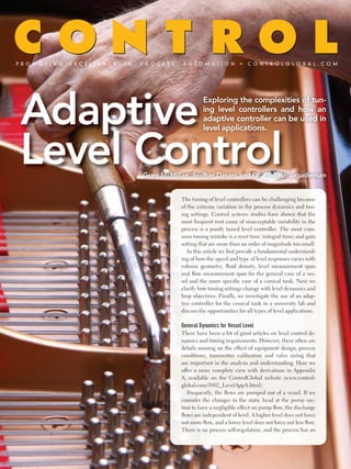
- 1. The tuning of level controllers can be challenging because of the extreme variation in the process dynamics and tun- ing settings. Control systems studies have shown that the most frequent root cause of unacceptable variability in the process is a poorly tuned level controller. The most com- mon tuning mistake is a reset time (integral time) and gain setting that are more than an order of magnitude too small. In this article we first provide a fundamental understand- ing of how the speed and type of level responses varies with volume geometry, fluid density, level measurement span and flow measurement span for the general case of a ves- sel and the more specific case of a conical tank. Next we clarify how tuning settings change with level dynamics and loop objectives. Finally, we investigate the use of an adap- tive controller for the conical tank in a university lab and discuss the opportunities for all types of level applications. General Dynamics for vessel Level There have been a lot of good articles on level control dy- namics and tuning requirements. However, there often are details missing on the effect of equipment design, process conditions, transmitter calibration and valve sizing that are important in the analysis and understanding. Here we offer a more complete view with derivations in Appendix A, available on the ControlGlobal website (www.control- global.com/1002_LevelAppA.html). Frequently, the flows are pumped out of a vessel. If we consider the changes in the static head at the pump suc- tion to have a negligible effect on pump flow, the discharge flows are independent of level. A higher level does not force out more flow, and a lower level does not force out less flow. There is no process self-regulation, and the process has an
- 2. LeveL Normally, the denominator of the integrating pro- cess gain that is the product of the density ( ), cross-sec- tional area (A) and level span (mass holdup in the control range) is so large compared to the flow rate that the rate of change of level is extremely slow. For horizontal tanks or drums and spheres, the cross-sectional area varies with level. In these vessels, the integrating process gain is low- est at the midpoint (e.g. 50% level) and highest at the op- erating constraints (e.g. low- and high-level alarm and trip points). Most people in process automation realize that a con- troller gain increased beyond the point at which oscil- lations start can cause less decay (less damping) of the oscillation amplitude. If the controller gain is further in- creased, the oscillations will grow in amplitude (the loop Figure 1. Conical Tank in MIT Anna University Lab with becomes unstable). Consequently, an oscillatory response an industrial DCS. is addressed by decreasing the controller gain. What most don’t realize is that the opposite correction is more likely integrating response. There is no steady state. Any unbal- needed for integrating processes. Most level loops are ance in flows in and out causes the level to ramp. When the tuned with a gain below a lower gain limit. We are fa- totals of the flows in and out are equal, the ramp stops. For miliar with the upper gain limit that causes relatively fast a setpoint change, the manipulated flow must drive past the oscillations growing in amplitude. We are not so cogni- balance point for the level to reach the new setpoint. If we zant of the oscillations with a slow period and slow decay are manipulating the feed flow to the volume, the feed flow caused by too low of a controller gain. The period and must be driven lower than the exit flow for a decrease in decay gets slower as the controller gain is decreased. In setpoint. The ramp rate can vary by six orders of magnitude other words, if the user sees these oscillations and thinks from extremely slow rates (0.000001%/sec) to exceptionally they are due to too high a controller gain, he or she may fast rates (1%/sec). The ramp rate of level in percent per sec- decrease the controller gain, making the oscillations ond for a 1% change in flow is the integrating process gain worse (more persistent). In the section on controller tun- (%/sec/% = 1/sec). The integrating process gain (Ki ) for this ing, we will see that the product of the controller gain general case of level control, as derived in Appendix A, is: and reset time must be greater than a limit determined by Ki = Fmax / [( * A) L max ] Eq. 1 Since the PID algorithm in nearly all industrial con- Conical tank trol systems works on input and output signals in percent, the tuning settings depend upon maximums. The flow maximum (Fmax) and level maximum (Lmax) in Equation r 1 must be in consistent engineering units (e.g. meters for level and kg/sec for flow). The maximums are the mea- h Variable- ow pump surement spans for level and flow ranges that start at zero. Fmax Most of the published information on process gains does not take into account the effect of measurement scales and valve capacities. The equation for the integrating Hand valve process gain assumes that there is a linear relationship between the controller output and feed flow that can be achieved by a cascade of level to flow control or a linear installed flow characteristic. If the controller output goes directly to position a nonlinear valve, the equation should Reservoir be multiplied by the slope at the operating point on the installed characteristic plotted as percent maximum ca- pacity (Fmax) versus percent stroke. Figure 2. Conical tank detail.
- 3. LeveL standards, interfaces and tools. The DCS allows graduate students and professors to explore the use of indus- try’s state-of-the-art advanced control tools. Less recognized is the oppor- tunity to use the DCS for rapid pro- totyping and deployment of leading edge advances developed from uni- versity research. The conical tank with gravity f low introduces a severe nonlinearity from the extreme changes in area. The de- pendence of discharge f low on the square root of the static head cre- ates another nonlinearity and nega- tive feedback. The process no longer Figure 3. Performance of linear PID level controller for a conical tank. has a true integrating response. In Appendix A online ( www.control- global.com/1002_LevelAppA.html), the process gain to prevent these slow must be increased to prevent slow os- the equations for the process time oscillations. cillations. constant ( p) and process gain (K p) In some applications, exception- Adaptive level controllers can not are developed from a material bal- ally tight level control, through en- only account for the effect of ves- ance applicable to liquids or solids. forcement of a residence time or a sel geometry, but also deal with The equations are approximations material balance for a unit operation, the changes in process gain from because the head term (h) was not is needed for best product quality. changes in f luid density and non- isolated. Since the radius (r) of the The quantity and quality of product linear valves. Even if these nonlin- cross-sectional area at the surface for continuous reactors and crystal- earities are not significant, the adap- is proportional to the height of the lizers depend on residence times. tive level control with proper tuning level as depicted in Figure 2, it is ex- For fed-batch operations, there may rules removes the confusion of the pected that the decrease in process be an optimum batch level. The allowable gain window, and prevents time constant is much larger than variability in column temperature the situation of level loops being the decrease in process gain with a that is an inference of product con- tuned with not enough gain and too decrease in level. centration in a direct material bal- much reset action. ance control scheme depends on the * r2 tightness of the overhead receiver Specific Dynamics for Conical Tank Level p = * h1/2 3*C level control. Since these overhead Conical tanks with gravity discharge Eq. 2 receivers are often horizontal tanks, flow are used as an inexpensive way to a small change in level can represent feed slurries and solids such as lime, h1/2 * Fmax Kp = a huge change in inventory and ma- bark and coal to unit operations. The C * L max nipulated ref lux f low. conical shape prevents the accumu- Eq. 3 In other applications, level control lation of solids on the bottom of the can be challenging due to shrink and tank. The Madras Institute of Tech- Controller Tuning Rules swell (e.g. boiler drums and column nology (MIT) at Anna University in The lambda controller tuning rules sumps) or because of the need for Chennai, India, has a liquid conical allow the user to provide a closed- the level to float to avoid upsetting tank controlled by a distributed con- loop time constant or arrest time the feed to downstream units (e.g. trol system (DCS) per the latest inter- from a lambda factor ( f) for self-reg- surge tanks). If the level controller national standards for the process in- ulating and integrating processes, re- gain is decreased to reduce the reac- dustry as shown in Figure 1. The use spectively. The upper and lower con- tion to inverse response from shrink of a DCS in a university lab offers the troller gain limits are a simple fall out and swell or to allow the level to float opportunity for students to become of the equations and can be readily within alarm limits, the reset time proficient in industrial terminology, enforced as part of the tuning rules
- 4. LeveL in an adaptive controller. An adaptive controller integrated into the DCS was used to For a self-regulating process the controller gain (Kc) and automatically identify the process dynamics (process model) for reset time (Ti) are computed as follows from the process gain the setpoint changes seen in Figure 3. The adaptive controller (K ), process time constant and process dead time ( p): employs an optimal search method with re-centering that finds the process dead time, process time constant, and process gain Ti that best fits the observed response. The trigger for process iden- Kc = tification can be a setpoint change or periodic perturbation au- Kp * ( * + ) f p p Eq. 4 tomatically introduced into the controller output or any manual change in the controller output made by the operator. Ti = p The process models are categorized into five regions as Eq. 5 indicated in Figure 4. The controller gain and reset settings computed from the lambda tuning rules are then automati- The upper gain limit to prevent fast oscillations occurs cally used as the level moves from one region to another. when the closed loop time constant equals to the dead time. This scheduling of the identified dynamics and calculated tuning settings eliminates the need for the adaptive control- p Kc < Kp * 2 * p Eq. 6 For an integrating process the controller gain (Kc) and reset time (Ti) are computed as follows from the integrating process gain (Ki) and process deadtime ( p): Ti Kc = Ki * [( f /Ki) + p ]2 Eq. 7 Ti = 2 * ( f /Ki ) + p Eq. 8 The upper gain limit to prevent fast oscillations occurs when the closed loop arrest time equals the dead time: Figure 4. Process models automatically identi ed for operat- ing regions. 3 Kc < Ki * 4 * p Eq. 9 The lower gain limit to prevent slow oscillations occurs when the product of the controller gain and reset time is too small. 4 Kc * Ti > Ki Eq. 10 Opportunities for Adaptive Control of Conical Tank Level A linear PID controller with the ISA standard structure was tuned for tight level control at 50% level for a detailed dy- namic simulation of the conical tank. Figure 3 shows that for setpoints ranging from 10% to 90%, a decrease in process time constant greater than the decrease in process gain at Figure 5. Performance of adaptive PID level controller for low levels causes excessive oscillations. conical tank.
- 5. LeveL ler to re-identify the process nonlinearity and tuning for dif- user from getting into the confusing situations of upper ferent level setpoints. It was found that the use of lambda and lower gain limits and the associated fast and slow os- time, rather than lambda factors, with protection against go- cillations. The smoother and more consistent response al- ing outside the controller gain limits helps provide a more lows the user to optimize the speed of the level loop from consistent tuning criterion. As seen in Figure 5, the adaptive fast manipulation of column reflux and reactor or crystal- level controller eliminates the oscillations at low levels, and lizer feed to slow manipulation of surge tank discharge provides a more consistent level response across the whole flow control. level range. Adaptive level controllers can eliminate tuning prob- Greg McMillan is a consultant and ControlTalk columnist. Sridhar Dasani is a graduate of Madras Institute of Technology (MIT ) Anna lems from the extreme changes in level control dynamics Universit y in Chennai India. associated with different equipment designs and operat- Dr. Prakash Jagadeesan is an assistant professor at Madras Institute of ing conditions. The integrated tuning rules prevent the Technology (MIT ) Anna Universit y in Chennai India. Reprinted with permission from Control Magazine, February 2010. On the Web at www.controlglobal.com. © PUTMAN. All Rights Reserved. Foster Printing Service: 866-879-9144, www.marketingreprints.com. ER-000131-Feb10