1. Wireless Machine Monitoring System
Introduction
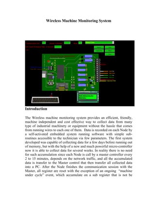
The Wireless machine monitoring system provides an efficient, friendly,
machine independent and cost effective way to collect data from many
type of industrial machinery or equipment without the hassle that comes
from running wires to each one of them. Data is recorded on each Node by
a self-activated embedded system running software with simple sub-
routines accessible to the technician via few parameters. The first system
developed was capable of collecting data for a few days before running out
of memory, but with the help of a new and much powerful micro-controller
now it is able to collect data for several weeks. In reality there is no need
for such accumulation since each Node is call by a master controller every
2 to 15 minutes, depends on the network traffic, and all the accumulated
data is transfer to the Master control that then transfer all collected data
into a PC. After the Node finishes the communication session with the
Master, all register are reset with the exception of an ongoing “machine
under cycle” event, which accumulate on a sub register that is not be
2. affected by the reset call. Accumulation then starts all over again on all
other registers.
At the moment we obtain different types of data that include: (Time in
seconds):
1- Cycle time = time it takes to completely machine a part or a full
process.
2- Idle time = the amount of time the machine is not under a cycle with
no alarm condition present.
3- Alarm Time = the amount of time the machine has been under an
alarm condition.
4- Machine Status = the actual status in which the machine is at the time
of transmission session.
5-Temperature = up to two temperature probe can be connected to the
module or one temperature sensor and one pressure transducer.
Possibilities of expansion are real. Since the Nodes or modules are fully
programmable, new functions are possible including extension to the
machine functions. With just this five data types mentioned above, the PC
software can trigger events as wanted, and logs special events to a log file.
This might help in understanding the capacity of each machine or in other
cases find why the equipment is not performing like it is supposed to.
Some of actual decision making capabilities those are available currently in
the system:
• Alarms are saved into a log file array which in turn entered to an
Access database table on a record that corresponds to the machine
under supervision.
• Excessive idle time is, part count per hour and other parameters are
also the log to the files. Each log entry is a time-stamp of the event
occurred; and the user will be able to determine the amount of time
the machine was under a particular status.
• The log file is nothing more than a column on the database table
with a memo type format. The reports are yet to be automated that
will allow the user to create new events to be logged dynamically, or
select the ones which are of interest.
3. Software Overview:
The software is made out of many different function and subroutines.
Some of the features like event-loggers and dynamic updates are already
discussed above.
The system is managed using five different types of software. Some of the
software suffered significant changes especially in the End/Device or Slave
module. We have numbered these changes but since this is totally different
module than the first one we name the version as follow:
• The Slave or End/Device module which runs the Slave Wireless
Monitoring System as Version 1.0.
• The Master which runs the Master Wireless Monitoring System as
Version 1.0
• The version of the PC software went through 3 version changes.
The PC also runs an .ASP 2.0 (ASP DOT NET) applications that
provide the means for users on the intranet to view the Database
tables under a friendly web site.
4. • User can view the data but can’t make changes to the database,
since the tables are connected through a virtual XML copy of the
original database in which we had made updates as impossible.
• When a user requests to enter the web site, the server runs the script
and sends the user a compiled version of the page. This prevent user
from viewing the source code (For data security purposes). It also
eliminates the need of installing software in each user machine
since the results are view in any web browser like Internet Explorer.
The last and the fifth software is used to configure and load
parameters into the End/Device module, eliminating the need of
going into the source code to make changes. The module is
configured by the selection of few parameters. More on this under
the slave configuration process section.
The PC software running in Amtec Elgin Plant #2 is capable to detecting
the machines under an alarm status and sends a text message to the
responsible personnel in a hierarchal way, based on the alarm rules set on
database. The persons to be contacted, the amount of time the machine is
allowed under an alarm status and the interval between the hierarchies
(people hierarchy) are dynamically obtained from this Microsoft Access
table. Rules for directing the phone calls are established by the authorized
persons. We just equipped the software with the means to make these a
dynamic function. Shift change summary reports had also been tested and
they works. A separated table is used by the software to get the email
address of each person that is authorized to get this report.
The XBEEPROO
5. The Master controller has unique software that allows the module to act as a
Master on a PAN system. The wireless system use the XBEEPRO sub-
module which is a ZigBee/IEEE 802.15.4
(http://www.maxstream.net/wireless/zigbee.php) compliant operating on a
Non/Beacon mode under a specific PAN (Personal Area Network) RF
protocol. Mesh routing is needed depending on the amount of machines
connected to the system, 14 machines and 6 routers for the master module
and each router can again have the same amount. This configuration allows
the master to connect to modules that in other situation will be out of range.
The 60 mill watt of transmission power allows this module to reach other
modules directly by up to 100 meters away inside a warehouse type building
and over 1000 meter open field. The routing feature makes possible the
creation of a mesh topology network, extending the communication range to
greater distances. All the modules are FCC approved in the United States,
and the technology has worldwide acceptances. Data is transfer wirelessly at
a rate up to 250 kbps in a 2.4 GHz carrier frequency. Each communication
session travels in preformatted packets carrying the address ID of the
End/Device Node, the source module ID address, join with any user data up
to 100 bytes per packet.
At the power up condition, the X-BEE runs it’s built on a Boot loader.
The Basic Micro handshakes with the XBEE loading the needed
parameters that in turn configure the X-BEE Node as a Coordinator that
resides on the Master module. Any error on the configuration process
causes a recall to the function until the XBEE agrees to accept the
parameters. Once the agreement is Ok by the XBEE the Master sends an
op-code to the PC requesting the address of the Nodes the Master would be
talking (communicating) to. The PC does not inform the user about this
process since it repeats every communication Cycle, but if an error
occurred inside this function the PC results in an error message displayed
on the Message Box area. This informs the user of communication
problems and any other abnormally. Complete disconnection between the
PC and the Master is sensed and displayed with a windows message box. I
wish to bring the software to the point where it will display the Error,
possible cause and the remedy.
6. The Basic Micro Atom Pro 28
Communication betweens the PC and the Master is done via an RS232
connection with a 57600 Baud rate, non inverted, 8 bit, and 1 stop bit
protocol using a DB9 to DB9 Serial communication cable. Operating
voltages for the module ranges from 6 to 24 volts DC. Two built-in voltage
regulators provide the Basic Micro with the +5 volts TTL level necessary
for Micro Controller and the IO operations. A secondary voltage regulator
provides around +3.125 volts CMOS level for the XBEEPROO module.
The Atom Pro 28 module executes around 100,000 instructions per second
and used a Basic type language to program it. It has 8 analogs to Digital 10
bit resolution inputs that can be used also as simple digital inputs/output,
plus 12 more 0 to +5 volts TTL logical level IO for a total of 20. A built-in
EPROM allows the programmer to save data to the non-volatile registers
and have this data ready for use in the event of power failure. Analog data
capture is possible at a rate of 6,000 samples per second. Even this is a 16
bit micro-controller is possible to allocate variables up to a 32 bit
resolution. The controller also supports floating-point math. Each pin can
be use to produce PWM signals, serial communication routines and a
regular TTL voltage of +5 volts digital level output. Pin 14 and 15 provide
7. access to a build in UART with a one byte long buffer size. The UART is
shared with the chip the TX and RX lines used to load the programs and
talk to the PC. We use most of this feature on this chip with the exception
of the PWM.
Master Module Overview:
The Master save any incoming data from a Node and it can either send a
request for more or drop the session. Each communication session results
are reported to the PC thought the serial port in an RS232 protocol. After
the Node session is terminated the Master move on and open a new session
with another Node.
With the array of Nodes address ID’s in the Basic Micro RAM the Basic
Micro start to call the Nodes in the order received from the PC. The Master
tries to engage a conversation with the End/Device if the End/Device
“respond timeout” parameter is overcome then the Master retries to
establish the connection and keeps on trying until the “Number of Retries”
parameter is overcome. If the “Number of Retries finish” event is trigger
8. the Master informs the PC with a Node address ID unreachable message.
The PC saves the event into the “Fail to connect” array with a Node ID
index. If the “Fail to Connect Count (NodeID)” array is overcome the
Node is flagged, the PC do not requests a connection to this module until
the “Time to try the Flagged Node” parameter is overcome by the
“Accumulation for Flagged Nodes” array with a Node ID Index. If it fail to
connect at the first time, after the PC granted the permission by “ try to
reach the Node again” event, the Node remains flag until the next
permission is obtain and the process continues forever unless the Node is
permanent flag on the PC by the use of the Node select check box. Taking
“not reachable Nodes” out of the communication cycle speeds the system.
The retrying to communicate routine with a dead Node can cost several
second on each communication cycle. If there are more than one Node
down, maybe the machine is down and has been locked/tagged out, or any
other reason, this seconds can add up to several minutes.
The Master pings the Node with a “AA” up code and then sits and wait
for a response from the Node until the “respond timeout” parameter is
overcome like we talked above, but if the Node is reach the Master is
granted with a packet from the Node having a double copy of the
accumulated values of the register on the End/Devices. The double copy of
the accumulated values is then passed to the PC. The PC splits the two
copies and compares them for data integrity analysis purpose. If the copies
do not match then an event is recorded to the log file and the “Data
Corrupted “array index flag is set to a true condition. The “Data Corrupted
counter” array is incremented also. If a “Data Corrupted” = true is present,
future data corrupted events are not log to the file but the “Data Corrupted
Counter” array continue to increment, the “Data Corrupted” flag remains
in the true condition. If new data packet from the Node comes with exact
copies and the “Data corrupted” flag for the node is true then the “Data
corrupted Counter (NodeID)” accumulated value is send to the log file, the
“Data Corrupted Counter (NodeID)” is reset to zero. This helps on
troubleshooting communication problems, which might require a channel
change or the need of new router installation to boost the signal, ensure
data integrity and prevent data lost. A Data corrupted session will be
analyzed by the PC anyway and the algorithm try to recover any possible
data from the packet, this prevent completely data lose and at least provide
the user with an approximation of the Node registers values. This is not the
ideal situation, since we don’t want uncompleted reports from the
machines, we are looking instead for reliable data, but since the system still
9. on the developing process I’m arming the software with any possible tool
that can be used on future analysis and debugging process. Is hard to fix a
problem if the problem can be see, and to me the best way to find it is to go
back and look at the data to determine what went wrong. So far the system
has been put under test very few times and turns out to be correct. Few of
the data discrepancies were found to be overlaid on the operator side and
not the Node computing calculations, but there is definitely a room for
improvements.
After the Node Address ID array index has been incremented enough to
overcome the “NodesCount” parameter, the Basic Micro calls a sleep
Routine that last for a period of time result of to the amount of Nodes
minus “Minimum Cycle Delay” parameter with a normal value around 90
seconds. The Purpose of this delay is mostly used on Networks with a
small amount of Nodes. The time each Node invests in sending packets to
the Master affects the ability of the Slave to provide exact values
accumulated on the registers. Having the Slave spending most of the time
on communication routines deprives the main task of monitoring the IO to
execute. The application does not require a constant data stream from each
Node and on the contrary we want the End/Devices to take care of
accumulating the data most of the time. We need to inform the reader that
this is not real multitasking system. Multitasking is done virtually because
of the hardware limitation, so we need to use the micro-controller
execution time mostly on calculating rather than talking.
When the Master comes back from the sleep period it sends a “Starting”
op-code message to the PC. The PC catches this message and triggers a
“start loading sequence” event. When the event is latch it calls a data
loader subroutine. The Master also jumps to a loading subroutine
sequence. After a handshake, the PC starts loading the Nodes addresses
together with any extra information wanted to pass into the Master. Each
Node ID address is passed to the Master and the Master responds with a
Data Acknowledge. The amount of Node ID Addresses to load into the
Master is specified by the first data value coming from the PC, after that
the Master makes sure the amount of data addresses received match this
value. If something goes wrong on this process the function watchdog
catch this event and forces a request to start over again call. The process
continues until data integrity is acknowledged by the Master. This loading
process is essential to ensure that changes to the network topology are pass
dynamically which can be cause by the addition of new Nodes or the
10. subtraction of Nodes no longer in use. Once the Master have the Nodes
addresses saved on the “AddressID” array it goes and start requesting the
attention of each Node again. Each communication session between the
two modules takes around 1 to 2 seconds.
The Master module and the Slave module are electrically identical. Most of
the electronics components are not use by the Master and they are intended
for the Slave operation. See the installation section for more information.
Slave Module Overview:
The XBEEPROO and Basic Micro Atom Pro 28 section applied in the
most to the slave module, with a difference that the Slave module runs the
Slave software. I explain the Slave configuration software together with
the Slave module explanation since it is a very small application.
Slave Configuration Process:
When the Slave module power up it goes into a 5 seconds waiting period
which is used to allow the module to accept a connection to a PC running the
configuration software. If the Slave is running when the PC connects via the
RS232 port with a Baud Rate of 9600 kbps, non-inverted, 8 bit, 1 stop bit
protocol, the event cause a hardware interrupt into the micro-controller. The
5 seconds delay now provide more than enough time for the micro-controller
to handshake with the PC and start loading the parameters. Every parameter
been loaded by the PC is granted with the acknowledge feedback from the
11. module. If for any reason this process is interrupted a communication error
is display on the PC message window. The module responds with a
parameter loading error as well. The algorithm does not provide ways to
recover from this error and will not attempt to figure out where is the
problem even though some of the problems can come from the PC, so the
user have to locate the problem and try to load the parameters again. There
are only few reason for this situation to happen which can be: no power
going into the Slave module, the RS232 serial cable is not connected
properly, wrong cable (a null modem cable maybe), wrong PC port
configuration, port on the PC in use by another application, Slave module
might be running the Master software, bad module board. Each module
board has an onboard green LED that provides a visual confirmation of the
power status going to the module. If power is present, we know we are using
the right cable, and the cable is connected properly, and then try to used any
communication terminal or the one provided by slave configuration
software. A common terminal that comes with windows is the hyper
terminal. Open the communication port on the PC and then cycle the power
to the module. The module should feedback the booting process which
include software version on the module and XBEE module. Having this data
on the display helps to determine if the right software is installed on the
module. If communication is not possible try to reboot the PC, or try a
different port if available.
Each Parameter is acknowledged by the modules is saved to the on board
EPROM. Saving this setting to EPROM as you might know, allow the
module to load the right setting after a power failure occurrence. After
loading the settings to the RAM the module used the values on the RAM
entries to configure the XBEEPRO and set the module into a Slave operating
condition. There are very few parameters to be loaded since I don’t see the
need to provide access to the user with all of them and most the parameters
are defaulted to constants values at this moment.
The slave configuration software is equipped with a communication terminal
that allows the used to see incoming data from the Slave and also send
commands to the module. This is a useful tool in my case for debugging
purpose. To used this terminal just click on the “Capture Now” button. If the
“trigger a reset when connecting” is check, which is check by default,
clicking the “Capture Now” button causes a hardware interrupt to the
module and the module goes into the boot up process. If the “Trigger a
12. Reset When Connecting” check box is un-check when button is click, then
no reset is performed but the terminal is ready to receive and send data.
The communication protocol is set by the two entries on the main form. An
example of the entry format is display when the tool tip appears over the
text box. The communication ports available on the PC are automatically
acquired by the program and ready for selection through the pull down
combo box. Access to the parameter is obtained by clicking on the “Show
Parameters” button. Every time the program is close the current settings are
save into a file. The next time the program opens it will look for this file and
load these values into the corresponding entry.
Parameters Explanation:
Actual parameters inside the module can be view by clicking the
“Retrieve” command button. This will cause a reset to the modules and after
the PC and Basic Micro handshake, the PC puts an up code requesting the
actual parameters values. The parameters are automatically display in the
corresponding data entries.
13. To set new parameters, set all the values as desire and then click the “Send”
command button. A reset to the modules is forces and after the hand shake
the parameters are load as explained on the above paragraphs.
The following are the list of few parameters.
Parameters Form
A-Module ID Number: Set a unique address number from the module.
Range from 1 to 1000.
B-Mode: There are only 8 modes available, 3 of which the user don’t
need we use them for debugging purpose. The other 5 are in use
in Plant #2 in Elgin. There is enough programs space to add
more. Every time a mode is selected the picture on the form
displays the proper IO connection. The parameter sets which
program will run during normal operation. The differences on
this programs is on the way the module looks at the IO and make
an analysis of machine process. The registers will be fill with the
results of this analysis.
14. Modes available:
1-Program Error Only use for debugging the abstract involve
make it impossible for me to explain this parameter in this
publication.
2-Semi-Auto Mode: Set the running program to monitor a semi
automatic operated machines. Two inputs are needed; “Alarm” and
“Cycle is running” conditions.
3-Automatic Mode: Set the running program to monitor an
Automatic operated Machine. Three inputs are needed; “Alarm”,
“Cycle is running” and “Cycle Start” conditions.
4-Counter Mode: Set the program to monitor the equipment
where the cycle time and any other data is not need by the
exception of the part out put count. One input is needed; “Count”
condition.
5-Air Compressor Mode: Set the program to monitor an air
compressor type of equipment. Since Cycle time does not apply to
this machine, I wrote a separate routine, which spend most of the
type calculating Temperature and Pressure reading. Four inputs are
needed; “Alarm”, “Running”, “Temperature probe” and “Air
pressure transducer” conditions.
6-Virtual Switch: Set the program to monitor a machine with a
very difficult to monitor IO. I encounter this situation on some of
the Chiron we have in Plant #2 where there is no interfaces
possible with the machine status. I used instead an M code from
the machine and in the case of the Chiron the pallet change event
to calculate the data. With only one M code free on these machines
it was very hard to come with a reliable interfaces. So far it has
shown to be very close to the real behavior of the machine. The
machine does not have the light tower option so I’m want to have
the Module generate this signal for the machine, using the two
option M codes provided by the module.
15. 7-IO test Mode: Set the program to monitor each Digital Input on
the board and send the status through the UART port to the PC.
This mode is used only for troubleshooting the module IO.
8-Analog Input test Mode: Set the program to monitor the two
analog inputs on the module and send the values through the
UART port to the PC. This mode is used for troubleshooting the
module analog to digital inputs.
C- De-bounce Time: Sets the minimum cycle time expected before the
part count is accepted as an ongoing true cycle.
This prevents the part count register from
incrementing when the machine is under a setup
issue or the tool replacement processes.
D- Timing Factor: Sets the multiplier value on the PC and the divided
value on the Basic Micro from with the calculation
will measure a one second period. The actual
programs on the Slave module takes around 110
milliseconds to executed, this will require a
division by 9 to provide a one second count.
E- PAN ID: Sets the PAN ID number. The Slaves and Master needs to
agree on the PAN ID number in order to communicate. If
the PAN ID is different on a Node then that Node will not be
able to be reach or not be able to reach others. Since the
ZigBee standard has world wide acceptances the
possibilities of a near by building running a similar protocol
are possible. Forcing the modules to talk on a specific PAN
number will provide the technician with a way to avoid
other networks interferences.
F- Communication Channel: Sets the communication channel where
the Nodes and Master will be exchanging there
conversations. This is another way to avoid
16. interferences from other networks since the Nodes
need to be on the same channel in order to engage
on a conversation. Another used is to find the
channel with the most effective decibels of
reception and transmission power.
G- A1 or A2 Register: This will be rarely used by the technician I put
just for debugging purpose. Leave it at 0 please.
How the programs on the Slave module collect the data?
I will explain the Semi-Auto mode and Automatic mode sub-routines. The
virtual switch mode is one of the more abstract one. One I which to try is
give the Slave module the ability to request machine programs from the
server and have them ready to be downloaded into the machine.
Semi-Auto mode:
There are two registers to handle cycle time timings, one register for alarm
status, one for idle status timings and one for part-count purpose. The semi-
auto mode sequences looks at input number two for an alarm status if no
alarm is present then it looks at input number one for a cycle running
condition. If no cycle is running then the program declares the machine
status as idling. Every condition starts the corresponding timer register
increment. If a cycle is running then like said before the cycle time first
register will start accumulating. If the signal is dropped before a minimum
cycle time parameter is bigger than the accumulated cycle time the
accumulated time is reset to zero, no part is count. If the signal is dropped
and the accumulated time is more than the minimum cycle time the register
one is copied onto the register two, register one is set to zero, and a part
count is saved on the parts counter register. If the master module engages a
conversation with the slave module under an ongoing cycle running period
the cycle running time register one is not affected, but the register two is
transferred and the other register are also transferred to the master module,
this register transferred are reset to zero. Before handling the values to the
17. master module the values are divided by the proper timing factor. The actual
status of the IO is also sent with the packet. There are algorithms in between
these sequences to filter incoming noise on the IO, and prevent false trigger
of the status events.