
Empfohlen
Weitere ähnliche Inhalte
Was ist angesagt?
Was ist angesagt? (20)
Andere mochten auch
Ähnlich wie 2917143 plywood-scooter
Ähnlich wie 2917143 plywood-scooter (20)
Kürzlich hochgeladen
Kürzlich hochgeladen (20)
2917143 plywood-scooter
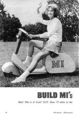
- 1. Man! This is it! Cost? $125. Does 75 miles to the 96 Mechanix Illustrated
- 2. By R. J. Capotosto DESIGNED and built just like a com-mercial model, the MI Scooter fea-tures an all metal frame covered with a wood body. The metal chassis provides the necessary strength. Angle iron was used because it is inexpensive and readily available at large hardware stores. Powered by a Clinton A 490 en-gine, the scooter has bicycle type hand controls for both the gas and brakes. Construction starts with the frame. Notch the angle, then bend cold. To pre-vent buckling at the bottom of the V, drill a 1/8-in. hole at the bottom of each notch. Make a test cut on a scrap piece first to determine exactly where to drill the hole and also to check the bend al-lowance. If you find after bending that the frame is warped, straighten it by bending the legs in the opposite direc-tion. Check for levelness on a flat sur-face. After cutting and bending all pieces, remove all burrs and bevel the edges slightly for a better weld. To weld, clamp the sections together as a unit and check against the drawing. If okay, weld all joints. The front fork bushing must be perfectly aligned when welded to the frame. Tack weld at sev-eral points, check and continue the weld. After finishing all welding, clean the joints with a chipping hammer to remove all slag and scale, then give the entire frame a coat of aluminum paint to prevent rust. The front fork is made by heating a 1/4x2-in. bar at two places and bending as shown. Align both legs of the fork then drill 3/4in. holes for the axle. Start with a small hole gradually increasing the size to % in. The steering post is in-serted into a hole drilled at the top of the fork. Let it protrude about 1/8 in. then weld securely. Alignment is impor-tant as steering efficiency originates at this point. Cut the post to the length indicated then grind a flat to act as a seat for the handle bar. Position the flat so that it is parallel to the axis of the wheel. Bend the handle bar from a piece of rigid con-duit and braze a shaft collar exactly in the center. The setscrew hole should face the rear so that it lines up with the flat on the steering post. The kick stand is fashioned from a piece of 3/8-in. bar stock. To obtain the small bends, it will be necessary to heat the rod to a dull red and bend in a vise. Drill the three small holes in the rod after bending. Two of these are for cot-ter pins to prevent side movement and the other hole is for the return spring. To keep the drill from "walking," grind a small flat spot, then center punch. At-tach the stand to the frame by means of small brackets cut from waste pieces of angle. Be sure to use lock washers or locking nuts when fastening the brackets. This applies to all other nuts where cotter pins are not used. The rear axle supports are made of 3/4-in. steel cut as illustrated. The blocks may be left "square" if you like, but rounding them off will look much neater. To shape the piece without diffi-culty, drill a series of small holes around the perimeter, overlapping the holes slightly. If any "ties" are left, cut these with a hack saw. A hole is drilled and tapped at the bottom of both blocks to take a hex head setscrew. A correspond-ing flat must be ground into the axle end to keep it from turning. The mounting holes for the brackets may be drilled at this time but the matching holes in the PLYWOOD SCOOTER gallon and has a cruising speed of 30 miles per hour. 97
- 3. frame are not put in until later. Tempo-rarily attach the wheel to the axle, then space with shaft collars. The wheel should be centered over the frame and the bracket temporarily held with small clamps. Adjust so that the wheel is parallel to the frame, then transfer the hole location from the block to the frame and drill. Mark the blocks to identify them so they will not be switched later. The sprocket and brake assembly are attached to the rear wheel as shown 1. Kick stand is formed from cold rolled rod. Brackets are angles bolted to frame. 2. Partially assembled scooter showing the angle iron chassis. Note the kick stand. 3. Rear axle supports are shaped by drilling series of holes. Hack saw for final cut. 98 4. Hole for steering rod should be cut before bending and gluing the mud guard. Mechanix Illustrated
- 4. in the diagram. The brake shoe bracket is welded to a shaft collar which in turn is welded to the axle support. If you use the Clinton A 490 engine as we did, drill the holes in the frame and mount as shown. If other engines are used some changes may be necessary. With the en-gine in place, install the clutch with sprocket side in and connect the roller chain. Allow a little play in the chain. If the linkage is such that it is too loose, place shims under the engine mounting plate to take up the slack. Adjust the position of the clutch on the shaft by leaving the clutch setscrew loose. Rotate the rear wheel several times by hand and the chain will automatically slide the clutch assembly to the proper posi-tion. Now tighten the setscrew. Since the engine is mounted in a "downhill" position, it will be necessary to mount the gas tank so that it will be in a horizontal plane. To do this, remove the bolt holding the front gas tank lug,
- 5. then carefully bend the tank upward. Add the flat bracket to hold the tank in this new position. The only other change on the engine is to direct the exhaust fumes out through the rear. The stock muffler which comes with the engine will dissi-pate the exhaust fumes into the body area and naturally this is objectionable. A length of flexible gas pipe (the type used for gas ranges) is ideal for this purpose. Connect one end to the present muffler and run the other end out through the rear. Drill a hole in the side of the muffler to take the pipe and plug up the original holes. The ridges in the pipe will help deaden the engine noise. The control lines are added at this time. The transmission for hand brakes and the three-speed hub is used for this purpose. Run both cables along the chassis and attach the left one to the brakes and the other to the throttle. A simple bracket is used to attach the cable assembly to the engine. Attach the cable to the swivel clamp on the throttle linkage. The engine may be stopped by the shorting clip or by use of a toggle switch connected to the low voltage side of the magneto and ground. To actuate the clip from outside the body, attach a short length of throttle control cable to the clip. When the control is pushed in the plug will be shorted out. The toggle switch method is neater. Run one lead from the switch to the low volt-age side of the magneto and the other lead to ground. Do not attempt to run a switch from the plug and ground as the spark will jump the gap and you'll get a shock to boot. 100 Mechanix Illustrated
- 6. 5. Front mud guard fits snugly over the fork. Check clearance of wheel and guard. 6. Handle bar cover is made ol laminated sections patterned in the manner shown. 7. Here it is—the completed scooter. A thrill to ride and a beauty to behold. Start the woodwork by cutting and and attaching the floor board. This is made of 1/2-in. plywood in two sections as shown. Notch the front end to fit around the fork bushing support. Drill and attach the boards with 1/4x20xl-in. bolts. The body is made next. This is made by laminating two thicknesses of 3/4-in. pine, gluing the sections as shown for rigidity. Pine is used because it can easily be shaped. The inner section must be set back 1/8-in. to allow for the thickness of the plywood covering. Lay-out the outer piece first and cut on the band saw. Sand smooth to remove all bumps then transfer the outline to the inner section. Now with a small divider, set with the legs 1/8-in. apart, strike off points around the perimeter about an inch apart, then connect the lines with the aid of a curve. This piece is also cut on the band saw. Line up the outer and inner sections carefully and glue securely. When the glue has set connect the sides by means of the cross members. Use glue and screws for added strength. With the body thus far completed, place it on the frame and check to make sure it fits properly. The 1/8-in. "bending" ply-wood is next prepared. The width to fit between the shoulders should be ex-act. Temporarily clamp the piece along the bottom edge and, pulling the wood tightly, mark off the length needed. Cut and glue into place. Be sure the grain runs across so that the wood will bend around the body. Use plenty of clamps and leave them on until the glue has set. If you think you will have difficulty bending the wood, you can pre-bend it by wetting and rolling into a cylinder and tying the roll till dry. If you use this method, be sure to cut the wood first as it would be rather difficult to cut afterward. Naturally the wood will not be the exact shape you need, but it will be easy to clamp into place. Use a waterproof glue. The front mudguard is made in a similar manner except that the sides are solid pine instead of built up sections. Drill the hole for the steer-ing post after the piece has been cut to size but before gluing. The 1/8-in. [Continued on page 128] 101
- 7. Mi's Plywood Scooter [Continued from page 101] plywood sides are glued to the body last of all. Cut the panels undersize so that you will have less wood to trim when rounding the edges. This also applies to the contoured floor section and steering post cover. When assembling the floor sec-tion, cut and fit the pieces directly on the part being covered. This will simplify construction as it eliminates guesswork. Allowance must be made to pass the con-trol cables which are fastened directly to the floor board. Also allow for the short sections of angle braces. The front of this part is made to fit over the steering post and enough clearance must be provided to pass the control cables. They must not bind on turns. The same applies for the steering post cover. Cut away inside and give cables plenty of room for turning. The handle bar cover is shaped to con-form to the bars as well as the steering post. The bottom of the cover is left flat so that it rests on the steering post cover. When the woodwork has been com-pleted, round off all edges with a router or with a rasp and plenty of elbow grease. Follow the rasping with sandpaper, first rough them medium followed by fine. The wood should be finished with a good undercoating and then at least two coats of exterior grade enamel. The cushion is made to fit into the tapered opening in the body so that it may be removed easily for starting and serv-icing the engine. Blue Boltaflex over foam rubber makes a very comfortable and good-looking seat. Make a one piece gusset and staple it to the bottom side. To keep the engine heat from damaging woodwork, interior of body is lined with Fiberglas insulation. It is available at most auto supply shops and it serves the purpose well. Use the one-inch material and at-tach it with staples. Be careful not to ob-struct the air intake at the front. Laws vary from state to state so check with the local authorities regarding lights, horn, signals, etc. For lights, use dry cells which can be stored in the engine compart-ment. The switch can be placed on the control panel. If stop lights are required, use an automobile replacement switch at-tached to the frame so it will be actuated by the brake rod linkage. The head light is from a six-volt lantern housing with a clear white fog lamp. Be sure to use an oil and gas mixture for fuel. Do not use ethyl or low grade white premium gas. White marine gas is ac-ceptable. Be sure fuel is fresh and mix well prior to filling tank. Now, fill 'er up— and away we go! (MI has made arrangements with the Finecraft Products Company, Box 7031, Jersey City 7, N. J. to supply readers with the parts for this scooter. Write to them for a price list.) 128 February, 1963