
Empfohlen
Weitere ähnliche Inhalte
Was ist angesagt?
Was ist angesagt? (12)
Andere mochten auch
Andere mochten auch (20)
Ähnlich wie 650 Series AC Drives from 0.3 to 150 Hp with Simple Setup and Operation
Ähnlich wie 650 Series AC Drives from 0.3 to 150 Hp with Simple Setup and Operation (20)
Mehr von youri59490
Mehr von youri59490 (20)
Kürzlich hochgeladen
Kürzlich hochgeladen (20)
650 Series AC Drives from 0.3 to 150 Hp with Simple Setup and Operation
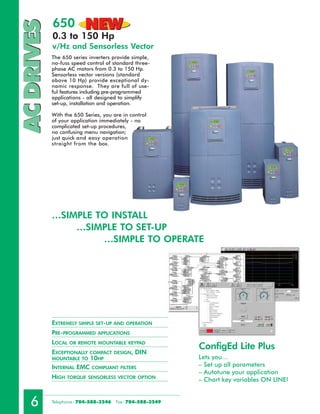
- 1. 650 NEW AC DRIVES 0.3 to 150 Hp v/Hz and Sensorless Vector The 650 series inverters provide simple, no-fuss speed control of standard three- phase AC motors from 0.3 to 150 Hp. Sensorless vector versions (standard above 10 Hp) provide exceptional dy- namic response. They are full of use- ful features including pre-programmed applications - all designed to simplify set-up, installation and operation. With the 650 Series, you are in control of your application immediately - no complicated set-up procedures, no confusing menu navigation; just quick and easy operation straight from the box. …SIMPLE TO INSTALL …SIMPLE TO SET-UP …SIMPLE TO OPERATE EXTREMELY SIMPLE SET-UP AND OPERATION PRE-PROGRAMMED APPLICATIONS LOCAL OR REMOTE MOUNTABLE KEYPAD ConfigEd Lite Plus EXCEPTIONALLY COMPACT DESIGN, DIN MOUNTABLE TO 10HP Lets you… INTERNAL EMC COMPLIANT FILTERS – Set up all parameters – Autotune your application HIGH TORQUE SENSORLESS VECTOR OPTION – Chart key variables ON LINE! 6 Telephone : 704-588-3246 Fax: 704-588-3249
- 2. AC DRIVES AC DRIVES 220-240V Single and Three-Phase Controllers Type Heavy Duty Standard Duty Frame Built-in Built-in Nominal Output Nominal Output Size Choke Brake Switch Power Current Power Current KW/Hp (A) KW/Hp (A) 650**/00F3/230/SNN* 0.25/0.3 1.5 650**/00F5/230/SNN* 0.3/0.5 2.2 1 650**/00F7/230/SNN* 0.55/0.75 3 – 650**/0001/230/SNN* 0.75/1 4 – – – 650**/0002/230/SNN* 1.5/2 7 2 650**/0003/230/SBN 2.2/3 9.6 3 650**/0005/230/SBN 4.0/5 16.4 YES 650V/0007/230/1BN 5.5/7.5 22 7.5/10 28 C 650V/0010/230/1BN 7.5/10 28 11/15 42 650V/0015/230/1BN 11/15 42 15/20 54 650V/0020/230/1BN 15/20 54 18/25 68 D DC 650V/0025/230/1BN 18/25 68 - - 650V/0030/230/1BN 22/30 80 30/40 104 E Optional 650V/0040/230/CBN 30/40 104 37/50 130 650V/0050/230/CBN 37/50 130 45/60 154 F AC 650V/0060/230/CBN 45/60 154 55/75 192 *Single-phase supply only. **Replace the 650 with 650V to select the sensorless vector option. 380-460V Three-Phase Controllers Type Heavy Duty Standard Duty Frame Built-in Built-in Nominal Output Nominal Output Size Choke Brake Switch Power Current Power Current KW/Hp (A) KW/Hp (A) 650**/00F5/460/SBN 0.3/0.5 1.5 650**/00F7/460/SBN 0.55/0.75 2 650**/0001/460/SBN 0.75/1 2.5 2 650**/0002/460/SBN 1.5/2 4.5 – – – YES 650**/0003/460/SBN 2.2/3 5.5 650**/0005/460/SBN 3.7/5 9 650**/0007/460/SBN 5.5/7.5 12 3 650**/0010/460/SBN 7.5/10 16 650V/0015/460/1BN 11/15 21 15/20 27 C 650V/0020C/460/1BN 15/20 27 18/25 34 650V/0025/460/1BN 18/25 38 22/30 45 DC 650V/0030/460/1BN 22/30 45 30/40 52 D 650V/0040D/460/1BN 30/40 52 37/50 65 650V/0050/460/1BN 37/50 73 45/60 87 E 650V/0060/460/1BN 45/60 87 55/75 105 Optional 650V/0075/460/CBN 55/75 105 75/100 125 AC 650V/0100/460/CBN 75/100 125 90/125 156 650V/0125/460/CBN 90/125 156 91/150 180 F 650V/0150/460/CBN 91/150 180 – – **Replace the 650 with 650V to select the sensorless vector option. Options Remote mount keypad and Serial port standard on all 650V model drives (for frames 1, 2, and 3, select 650V and replace the ‘S’ in the part number with a ‘R’ to select this option) For example, change 650/0010/460/SBN to 650V/0010/460/RBN for a standard, 10 Hp, 650 sensorless vector controller with a remote mountable keypad. Brake Switch (optional above 15 Hp) (replace the ‘B’ in the part number with a ‘N’ to omit this option) For example, change 650V/0040/460/SBN to 650V/0040/460/SNN for a standard, 40 Hp, 650 sensorless vector controller with a brake switch. Internal EMC filter (up to 10 Hp) (replace the ‘N’ in the part number with a ‘F’ to select this option) For example, change 650/0010/460/SBN to 650V/0010/460/SBF for a 10 Hp, 650 sensorless vector con- troller with an internally mounted EMC filter. For external footprint style EMC filters (15 to 150 Hp), see page 26. Telephone : 704-588-3246 Fax: 704-588-3249 7
- 3. 650 POWER SUPPLIES AC DRIVES 0.3 to 150 Hp Digital I/O supply - 24 VDC (50 mA) Analog reference supply - 10 VDC (10 mA) TECHNICAL SPECIFICATION Power Supply - Single phase units; 220-240 VAC ±10%; 50-60 Hz ±5% Three phase units; 380-460 VAC ±10%; 50-60 Hz ±5% STOP Ambient - 0-40°C (32-104°F); derate 2% per °C to 50°C JOG (122°F) maximum REV DIR Altitude - 1000m (3280 ft.) ASL; derate 1% per 100m START (328 ft.) above 1000m (3280 ft.) to 5000m (16400 ft.) max. SPEED Overload - 150% for 30 seconds (heavy duty) REFERENCE 115% for 30 seconds (standard duty) Output Frequency - 0-240 Hz Environmental Protection - IP20 FRAME 1,2,3 Analog Inputs - 2; Speed control (0-10V, 4-20mA) Analog Output - 1; User configurable for DEMAND / CURRENT / PID ERROR / RAISE-LOWER OUTPUT (0-10V) Digital Inputs - 2; User configurable start/stop/direction/ pre-set speeds (8) START REV DIR JOG STOP Digital Input/Outputs - 2; User configurable as inputs or outputs SPEED REFERENCE Digital Relay Outputs - 1; User configurable relay out- puts (1A @ 240V) FRAME C-F All digital outputs configurable for AT SPEED / AT ZERO SPEED / RUNNING / HEALTHY / TRIPPED. Motor Thermistor Input Dimensions Frame Size Mounting Weight Size (Kg/Lbs) H W D H1 H2 W1 1 142/5.6 74/2.9 142/5.6 132/5.2 0.9/1.9 2 200/7.9 74/2.9 173/6.8 188/7.4 – 1.4/3.1 3 259/10.2 97/3.8 200/7.9 242/9.5 2.7/5.9 – C 348/13.7 201/7.9 208/8.1 335/13.2 2 9.3/20 D 453/17.8 252/9.9 245/9.6 471/17.3 17.4/38 150/5.9 E 668/26.3 257/10.1 312/12.12 630/24.8 8 22.5/50 F 720/28.9 257/10.1 349/13.7 700/27.5 29/64 All dimensions in millimeters/inches. STANDARDS W The 650 series meets European and D North American standards when installed in accordance with relevant product manual. H FRAME 1,2 & 3 FRAME C & D FRAME E & F 8 Telephone : 704-588-3246 Fax: 704-588-3249
- 4. SIMPLE TO USE SIMPLE TO SETUP AC DRIVES AC DRIVES – No languages to learn – Reduced menus show only key parameters Select from five internal programs to control your ap- – Software programmable with remote keypad option plication or manually configure the drive as required. The programs configure the drive’s inputs, outputs and pa- rameter list automatically. The applications include: – Basic Speed Control - voltage or current speed de- mand with digital start/stop and direction. – Manual/Auto Control - switch between a local and remote speed demand signal. – Preset Speeds - select up to 8 pre-programmed speeds using digital inputs. SIMPLE TO OPERATE The 6511 keypad is used for configuring and controlling the drive. Its design includes a back-lit LCD, 4-digit readout – Raise/Lower - increase and decrease speed from raise with indicators for motor rotating and direction, local/ and lower digital inputs. remote operation, parameter type (diagnostic or setup), and units. The standard keypad is drive mounted and removable. The remote keypad option lets the keypad mount up to three meters from the drive. It also includes a P3 port that can be used to program the drive with CELite+ software. Parameter Type Units Rotation Local Remote – PID Control - control pressure, flow, temperature or other variable by monitor transducer feedback. Start Stop Raise / Lower Speed ProgramMenu Telephone : 704-588-3246 Fax: 704-588-3249 9