Workshop - Best of Both Worlds_ Combine KG and Vector search for enhanced R...
Unit i edited
1. UNIT – I
ILLUMINATION AND ELECTRICAL SERVICES
1.1. Basics of electrical system
As consumers, we use electricity for various purposes such as lighting, heating, cooling, used in street
lightning, flood lighting, sporting arena, agriculture, locomotives and to various electrical appliances.
1.1.1 Let us know what actually Electricity is:
All matter such as solids, liquids, and gases, is composed of atoms. Therefore, the atom is considered to be
the basic building block of matter. However, atoms are almost always grouped together with other atoms to
form what is called a molecule. Only a few gases such as helium are composed of individual atoms as the
structural unit.
Electrons are the smallest and lightest of the particles in an atom. Electrons are in constant motion as they
circle around the nucleus of that atom. Electrons are said to have a negative charge, which means that they
seem to be surrounded by a kind of invisible force field. This is called an electrostatic field. Protons are much
larger and heavier than electrons. Protons have a positive electrical charge. This positively charged electrostatic
field is exactly the same strength as the electrostatic field in an electron, but it is opposite in polarity. The
proton is exactly as positive as the electron is negative.
Since the electron is much smaller and lighter than a proton, when they are attracted to each other due to
their unlike charges, the electron usually does most of the moving. This is because the protons have more mass
and are harder to get moving. Although electrons are very small, their negative electrical charges are still quite
strong. Remember, the negative charge of an electron is the same as the positive electrical charge of the much
larger in size proton. This way the atom stays electrically balanced. Each basic element has a certain number of
electrons and protons, which distinguishes each element from all other basic elements. In most elements, the
number of electrons is equal to the number of protons. This maintains an electrical balance in the structure of
atoms since protons and electrons have equal, but opposite electrostatic fields.
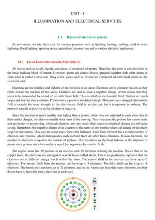
The copper atom has 29 protons in its nucleus with 29 electrons orbiting the nucleus. Notice that in the
copper atom, the electrons are arranged in several layers called shells. This is to graphically represent that the
electrons are at different energy levels within the atom. The closest shell to the nucleus can have up to 2
electrons. The second shell from the nucleus can have up to 8 electrons. The third shell can have up to 18
electrons. The fourth shell can have up to 32 electrons, and so on. Atoms can have this many electrons, but they
do not have to have this many electrons in each shell.
2. The greater distance between the electrons in the outer shells and the protons in the nucleus mean the outer
shell electrons experience less of a force of attraction to the nucleus than do the electron in the inner shells.
Notice that in the copper atom pictured above that the outside shell has only one electron. This represents that
the copper atom has one electron that is near the outer portion of the atom. The outer shell of any atom is called
the valence shell. When the valence electron in any atom gains sufficient energy from some outside force, it can
break away from the parent atom and become what is called a free electron. Atoms with few electrons in their
valence shell tend to have more free electrons since these valence electrons are more loosely bound to the
nucleus. So in materials like copper, the electrons are so loosely held by the atom and so close to the
neighbouring atoms that it is difficult to determine which electron belong to which atom.
Under these conditions, the valence or free electrons tend to drift randomly from one atom to its
neighbouring atoms. Under normal conditions the movement of the electrons is truly random, meaning they are
moving in all directions by the same amount. However, if some outside force acts upon the material, this flow
of electrons can be directed through materials and this flow is called electrical current. Materials that have free
electrons and allow electrical current to flow easily are called conductors. Many materials do not have any free
electrons. Because of this fact, they do not tend to share their electrons very easily and do not make good
conductors of electrical currents. These materials are called insulators.
Electricity is a term used to describe the energy produced (usually to perform work) when electrons are
caused to directional (not randomly) flow from atom to atom. In fact, the day-to-day products that we all benefit
from rely on the movement of electrons. This movement of electrons between atoms is called electrical current.
It is very important to have a way to measure and quantify the flow of electrical current. When current flow is
controlled it can be used to do useful work. Electricity can be very dangerous and it is important to know
something about it in order to work with it safely. The flow of electrons is measured in units called amperes.
An ammeter is this instrument and it is used to indicate how many amps of current are flowing in an electrical
circuit.
There is another important property that can be measured in electrical systems. This is resistance, which is
measured in units called ohms. Resistance is a term that describes the forces that oppose the flow of electron
current in a conductor. All materials naturally contain some resistance to the flow of electron current. Also due
to electrical signals produced in human body allows occurring heartbeat, brain to react and human body offers
resistance, the resistance offered by human body varies from person to person depending on factors such that
dry or wet, length of arm, path of current etc.,
1.1.2. Generation of Electricity
The fundamental principles of electricity generation were discovered during the 1820s and early 1830s by
the British scientist Michael Faraday. His basic method is still used today: electricity is generated by the
movement of a loop of wire, or disc of copper between the poles of a magnet.” Whenever there is change in the
flux linking the coil an emf will be induced across the coil” the induced emf will be ac in nature.
3.
4. 1.2 Single phase and three phase
Electricity flows in two ways; either in alternating current (AC) or in direct current (DC). Electricity or
'current' is nothing more than moving electrons along a conductor. Therefore, the difference between AC and
DC has to do with the direction in which the electrons flow. In DC, the electrons flow steadily in a single
direction, In AC, electrons keep switching directions, sometimes going positive and then going negative.
Direct current may be obtained from an alternating current supply by use of a current-switching
arrangement called a rectifier, which contains electronic that allow current to flow only in one direction.
Because of the significant advantages of alternating current over direct current in transforming and
transmission, electric power distribution is nearly all alternating current today. In the mid-1950s,
HVDC transmission was developed, and is now an option instead of long-distance high voltage alternating
current systems. Direct current is used to charge batteries, and in nearly all electronic systems, as the power
supply. Very large quantities of direct-current power are used in production of aluminium and
other electrochemical processes. Direct current is used for some railway propulsion, especially in urban
areas. High-voltage direct current is used to transmit large amounts of power from remote generation sites or to
interconnect alternating current power grids.
AC stands for alternating current, which is an electrical current that frequently reverses direction. AC
electricity is measured according to its cycles, with one complete cycle being counted each time a given current
travels in one direction and then doubles back on itself. An electrical current is able to complete many cycles
per second, and is then given its frequency rating based on that number; for example, the typical frequency in
India is 50 hertz (Hz), which indicates that the current is performing 50 cycles per second. AC power is the type
of electricity most commonly used in homes and offices, and is extremely versatile because its voltage can be
changed through a transformer to suit a variety of transmission needs. Any appliance that "plugs into the wall"
uses alternating current (note, however, that many of those same appliances may convert the AC into DC
internally). Anything household item that uses a battery runs on Direct Current (DC).
Advantages of DC
1. It can be stored, where a.c. cannot be stored directly
2. It gives a repelling shock to a person.
3. The resistance offered is less therefore the losses are minimized.
4. There will be no electromagnetic interference
5. Skin effect and proximity effect are absent in D.C.
6. D.C transmission is economical for long distances.
Advantages of AC
1. The generation of A.C is cheaper and simple than that of D.C generation.
2. A.C machine are simple and robust and do not require much attention for their repairs and
maintenance.
3. Wide range of voltages can be obtained by using transformers.
4. There will not be any commutation problem in generation.
5. No limitations for using circuit breakers.
5. 6. Most of the consumers require a.c supply.
Again in A.C power can be used as a single phase or as a balanced poly phase system. A phase is
nothing but a winding having two ends. Three-phase electric power is a common method
of alternating-current electric power generation, transmission, and distribution. It is a type
of polyphase system and is the most common method used by electrical grids worldwide to transfer
power. It is also used to power large motors and other heavy loads. A three-phase system is usually
more economical than an equivalent single-phase or two-phase system at the same voltage because it
uses less conductor material to transmit electrical power.
Three-phase has properties that make it very desirable in electric power systems:
• The phase currents tend to cancel out one another, summing to zero in the case of a linear balanced load.
This makes it possible to reduce the size of the neutral conductor; all the phase conductors carry the
same current and so can be the same size, for a balanced load.
• Power transfer into a linear balanced load is constant, which helps to reduce generator and motor
vibrations.
• Three-phase systems can produce a magnetic field that rotates in a specified direction, which simplifies
the design of electric motors.
Most household loads are single-phase. In India single-family dwellings, three-phase power
generally does not enter the home; multiple-unit apartment blocks may have three-phase power but
three-phase power is not used for household appliances. Utilities that supply three-phase power for
lower-load-density area homes typically distribute only one phase to individual loads. Some large
European appliances may be powered by three-phase power, such as electric stoves and clothes
dryers.
Note: Always for any phase system it has to be provided with neutral wire, such that if the
system is unbalanced, the current takes the return path via neutral wire.
1.2.1 Different wiring system
(a) Single phase two wire system: Comprises a line conductor and a neutral conductor. The
line conductor will be at nominal potential of 230V with respect to neutral line. Best suited
for residential supply.
(b) Single phase three wire system: It describes a standard American residential supply, in
which secondary winding of supply transformer is centre tapped and earthed proviging the
neutral, while opposite ends of secondary winding provide the two line conductors. Loads
connected between the line conductors are at 230V, whereas loads connected between either
of line conductor and neutral are at 120V.
6. Single phase two wire system
Single phase three wire system
(c) Three phase three wire systems: It may be star or delta connected. If it is star connected,
then its neutral is grounded. The large consumers like factories which need bulk power are
directly supplied from the substations.
(d) Three phase four wire systems: The fourth wire in this system is neutral and hence
transformer secondary in such system is always star connected. This system is generally
preferred for secondary distribution. The single phase loads are connected between one of
the three lines and neutral line, while three phase loads can be given to three phase supply
directly along with neutral for internal distribution.
Three phase three wire systems
8. 1.3 Protective Devices in Electrical Installation
When speaking about the protection of electrical installation, the most often meant is the overcurrent
protection. This is the protection that must be activated in case of exceedingly high currents in an installation It
can be achieved using safety fuses, or (automatic) circuit breakers; there are two other names: LS and MCB
switches. The task of that protection is to switch out faulty circuits, and thereby protect the loads that are
connected to those circuits, thus preventing the.
1.3.1 Fuses:
The fuse consists of a short length of thin wire. When the current flow is greater than the fusing current
of the fuse, it will get hot and burn (melt), thus interrupting the fault current before damage could be caused.
A fuse interrupts excessive current (blows) so that further damage by overheating or fire is prevented.
Wiring regulations often define a maximum fuse current rating for particular circuits. Over current protection
devices are essential in electrical systems to limit threats to human life and property damage. The time and
current operating characteristics of fuses are used to provide adequate protection without needless interruption.
Slow blow fuses are designed to allow harmless short term higher currents but still clear on a sustained
overload. Fuses are manufactured in a wide range of current and voltage ratings to protect wiring systems and
electrical equipment. Self-resetting fuses automatically restore the circuit after the overload has cleared; these
are useful, for example, in aerospace or nuclear applications where fuse replacement is impossible.
There are 3 general types of fuses.
1) Re-wirable (semi-enclosed) fuse
2) Cartridge fuse
3) High-rupturing capacity (HRC) fuse – a development of the cartridge fuse
1.3.1.1 Semi-enclosed (re-wirable) fuse is a simple device. It consists of a short length of wire, generally of
tinned copper. The current at which the wire melts depends on the length of the wire and its cross sectional area
(R=ρl/A).
Re-wirable fuse holders
Advantages
• The re-wirable fuse is cheap,
Disadvantages
Deterioration with time due to oxidation - may operate at lower currents than expected due to the
reduction in cross sectional area and hence increase in resistance.
9. Very easy for an inexperienced person to replace a blown fuse-element with a wire of incorrect size or
type.
Calibration of re-wirable fuse can never be accurate
The time taken for the fuse to blow may be enough to bring damage to circuit conductors and the
equipment being protected
1.3.1.2 Fully enclosed (cartridge) fuse: Fuse wire is enclosed in an evacuated glass tube with metal end
caps
Advantages
• Non-deterioration of the fuse element
• Usually more accurate
Disadvantages
• More expensive to replace
1.3.1.3 The HRC fuse is usually a high-grade ceramic barrel containing the fuse element. The barrel is usually
filled with sand, which helps to quench the resultant arc produced when the element melts.
1.3.2 Circuit breakers:
In new buildings are in dwelling electrical installations almost exclusively used circuit breakers owing
to their numerous advantages:
• simple use,
• multiple use (no replacement is needed after operation),
• smaller size, increased safety.
10. There is a large choice of circuit breakers by various manufacturers on the market. Their basic technical
characteristics are:
• rated current,
• breaking characteristic,
• short-circuit capacity, etc.
When choosing the breaking characteristics, usually are available B, C and (sometimes) also D –
complying with the IEC 60898 standard. For a residential installation the most often used is B characteristic. A
circuit breaker (according to requirements of the standard) must be strong enough to break a circuit three times,
and still preserve specific technical characteristics required.
In circuit breakers the automatic operation is done by using magnetic or thermal mechanism.
Advantages of mcb s over fuses are
Non destructive determination of tripping characteristics
Shorter tripping times under moderate over currents than with fuses
Immediate indication of faulty circuit
Reclosing can be effected at once after the fault has been cleared
No stock of fuses are required
Can be easily used as a circuit control switch when needed
1.3.2 Lightning arrestors
The role of the building protection system is to protect it against direct lightning strokes.
The system consists of:
The capture device: the lightning protection system
Down-conductors designed to convey the lightning current to earth
"crow's foot" earth leads connected together
Links between all metallic frames (equipotential bonding) and the earth leads.
When the lightning current flows in a conductor, if potential differences appear between it and the frames
connected to earth that are located in the vicinity, the latter can cause destructive flashovers.
11. 1.3.3 Earthing
The main reason for doing earthing in electrical network is for the safety. Earthing is a safety device used to
prevent a shock due to leakages arising from weak insulation, breaking of the element or otherwise. The metal
bodies of appliances handled like the electric iron, kettle or refrigerator must be earthed, that is, connected to a pipe
leading deep into the earth on to a metal plate. In case the metal body becomes live, the circuit is completed through
the live wire and the earth, resulting in a high current. The fuse on the live-wire side should blow out immediately,
and the matter should be investigated and the fault rectified. In case the fuse does not blow out, and a person
touches it, a severe shock is still prevented. This is because most of the current flows directly to the earth via the
earth connection which has negligible resistance. An extremely small current, if at all, may pass through the person’s
body which offers a resistance, resulting in only a mild shock.
For an earth connection, a three-pin socket and plug are required. Due to the high current it draws, the earth
pin is made thicker and larger than the other two pins. This ensures that the plug fits firmly into the socket,
reducing the chances of sparking. The heat caused by sparking causes the terminals to wear off and damages the
socket and the plug. Because it is larger, the earth connection is made first acting as a safety device.
Purpose of Earthing:
(1) Safety for Human life/ Building/Equipments
(2) Over voltage protection
(3) Voltage stabilization
Method for Construction of Earthing Pit (Indian Electricity Board):
a. Excavation on earth for a normal earth Pit size is 1.5M X 1.5M X 3.0 M.
b. Use 500 mm X 500 mm X 10 mm GI Plate or Bigger Size for more Contact of Earth and reduce Earth
Resistance.
c. Make a mixture of Wood Coal Powder Salt & Sand all in equal part
12. d. Wood Coal Powder use as good conductor of electricity, anti corrosive, rust proves for GI Plate for long
life.
e. The purpose of coal and salt is to keep wet the soil permanently.
f. The salt percolates and coal absorbs water keeping the soil wet.
g. Care should always be taken by watering the earth pits in summer so that the pit soil will be wet.
h. Coal is made of carbon which is good conductor minimizing the earth resistant.
i. Salt use as electrolyte to form conductivity between GI Plate Coal and Earth with humidity.
j. Sand has used to form porosity to cycle water & humidity around the mixture.
k. Put GI Plate (EARTH PLATE) of size 500 mm X 500 mm X 10 mm in the mid of mixture.
l. Use Double GI Strip size 30 mm X 10 mm to connect GI Plate to System Earthling.
m. It will be better to use GI Pipe of size 2.5″ diameter with a Flange on the top of GI Pipe to cover GI Strip
from EARTH PLATE to Top Flange.
n. Cover Top of GI pipe with a T joint to avoid jamming of pipe with dust & mud and also use water time
to time through this pipe to bottom of earth plate.
o. Maintain less than one Ohm Resistance from EARTH PIT conductor to a distance of 15 Meters around
the EARTH PIT with another conductor dip on the Earth at least 500 mm deep.
p. Check Voltage between Earth Pit conductors to Neutral of Mains Supply 220V AC 50 Hz it should be
less than 2.0 Volts.
Conventional methods of earthing:
(1) Plate type Earthing:
Generally for plate type earthing normal Practice is to use
Cast iron plate of size 600 mm x600 mm x12 mm. OR
Galvanized iron plate of size 600 mm x600 mm x6 mm. OR
Copper plate of size 600 mm * 600 mm * 3.15 mm
Plate burred at the depth of 8 feet in the vertical position and GI strip of size 50 mmx6 mm bolted with
the plate is brought up to the ground level.
These types of earth pit are generally filled with alternate layer of charcoal & salt up to 4 feet from the
bottom of the pit.
(2) Pipe type Earthing:
For Pipe type earthing normal practice is to use
GI pipe [C-class] of 75 mm diameter, 10 feet long welded with 75 mm diameter GI flange having 6
numbers of holes for the connection of earth wires and inserted in ground by auger method.
These types of earth pit are generally filled with alternate layer of charcoal & salt or earth reactivation
compound.
Pipe Earthing Vs Plate Earthing:
Suppose Copper Plate having of size 1.2m x 1.2m x 3.15mm thick. soil resistivity of 100 ohm-m,
The resistance of Plate electrode to earth (R)=( r/A)X under root(π/A) =
(100/2.88)X(3.14/2.88)=36.27 ohm
Now, consider a GI Pipe Electrode of 50 mm Diameter and 3 m Long. soil resistivity of 100 Ohm-m,
The resistance of Pipe electrode to earth (R) = (100r/2πL) X loge (4L/d) = (100X100/2X3.14X300) X
loge (4X300/5) =29.09 Ohm.
From the above calculation the GI Pipe electrode offers a much lesser resistance than even a copper
plate electrode.
As per IS 3043 Pipe, rod or strip has a much lower resistance than a plate of equal surface area.
13. 1.4 Electrical installations in buildings
Major components in building
1 Residential circuits
2 Improving power consumption
3 Sockets
4 Switches
5 Cables
6 Protection devices
7 Service panel
8 Distribution panels
9 Electrical symbols
1.4.1. Residential Circuits
Residential loads are connected in parallel, since the voltage remains the same through the loads and if a circuit
fails it does not affect the others
Purely resistor load (e.g. lights, toaster)
Demand P = VIcosΦ ,cosΦ is the power factor
If a motor is added (e.g. celing fan, refrigerator)
Demand Q = VIsin Φ as well as P, sin Φ is the reactive factor
1.4.2. Improving Power Consumption
Add a capacitor/capacitor block in parallel to the load which is reactive in nature.
1.4.3 Sockets
AC power plugs and sockets are devices that allow electrically operated equipment to be connected to
the primary alternating current (AC) power supply in a building. Electrical plugs and sockets differ
in voltage and current rating, shape, size and type of connectors
Examples
115V @ 15A
115V @ 20A
230V @ 30A
14. 1.4.4 Switches
In electrical engineering, a switch is an electrical component that can break an electrical circuit, interrupting
the current or diverting it from one conductor to another.
The most familiar form of switch is a manually operated electromechanical device with one or more sets
of electrical contacts, which are connected to external circuits. Each set of contacts can be in one of two states:
either "closed" meaning the contacts are touching and electricity can flow between them, or "open", meaning
the contacts are separated and the switch is non conducting.
Electrically, a "3-way" switch is a Single-Pole, Double-Throw (SPDT) switch. By correctly connecting two of
these switches together, toggling either switch changes the state of the light from off to on, or on to off. The
switches may be arranged so that they are in the same orientation for off, and contrasting orientations for on.
A "4-way" switch is a Double-Pole, Double-Throw (DPDT) switch, internally wired to reverse connections
between the input and output. It can be purpose-built, or can be implemented by adding appropriate external
wires to an ordinary DPDT switch. It has two pairs of "traveller" terminals that it connects either straight
through, or crossed over (transposed, or swapped).
By connecting one or more 4-way switches in-line, with 3-way switches at either end, the light can be
controlled from three or more locations. Toggling any switch changes the state of the light from off to on, or
from on to off.
Three way switches
16. Electrical wiring in general refers to insulated conductors used to carry electricity, and associated devices.
Red – hot, connection from the AC source to switch typically
Black – return, connection from switch to load
Green – ground, protects people from electrically charged metal parts
TYPES OF WIRES
1. Triplex wire
Triplex is an aerial cable that the utility company uses to feed the power pole. This wire ties to the wires sticking out of
the weather head.
2. Main Feeder Wires
These wires are usually type THHN wire and are rated for 125% of the load required. These are usually black
insulated wires coming out of the service weather head.
3. Panel Feed Wires
17. These wires are also type THHN, like the main feeders. They would be rated at 125 amps. This would protect
the wires if the amperage was a full 100 amps.
4. Single Strand Wire
When your home is piped, you’ll have to have another type of wire. Single strand wire is insulated and many of
these can be pulled into the same pipe. Normally, you’ll be using THHN wire for this installation.
5. Non-Metallic Sheathed Wire
18. This wire, commonly called Romex, is a plastic coated wire that has either two or three conductors and a bare
ground wire. This is the typical wiring used in most homes. The rating for this wire is either 15 amps, 20 amps,
or 30 amps, depending on the installation. This type is mostly used in residential purpose.
1.4.6 Distribution panel
A distribution board is a panel or enclosure that houses the fuses, circuit breakers, and ground leakage
protection units used to distribute electrical power to numerous individual circuits or consumer points. The board
typically has a single incoming power source and includes a main circuit breaker and a residual current or earth
leakage protection device. Older distribution boards may include a series of fuses which supply the individual
circuits; newer installations typically feature mini circuit breakers. A distribution board may be used to distribute
either single or three phase supplies depending on the installation specifics. Although distribution board equipment,
layouts, and legislative requirements differ from country to country, the basic principles of “distributing” a single
supply to various individual points while ensuring safety and control for each remains the same.
Distribution boards are common place in most industrial installations and commercial or residential buildings. Most
consist of a panel or enclosure supplied with a single incoming electrical feed cable. The power is then split among
several small circuit breakers or, in the case of older boards, fuses which in turn feed power to different
consumption points or circuits. The core function of any distribution board is to allow individual circuits to draw
power from correctly rated circuit breakers and for those circuits to be isolated without causing a disruption to the
rest of the supply. Most importantly though, the distribution board offers protection to users and equipment from
electrical shock or fire resulting from ground fault
1.4.7 Service Panel
19. The service box and distribution panel contain the main disconnect and fuse or main circuit breaker, the fuses
or circuit breakers which protect each individual circuit in the building, and the grounding connection for the
system. They make up the main electrical control centre for home or cottage wiring. The service conductors
from the load side of the meter socket are connected to the line side terminals inside the service box. The
distribution panel may be part of the main service box or may be a separate panel. However, when the
distribution panel and the main service box are combined, it is called a combination panel.
1.4.8 Substation
A substation is a part of an electrical generation, transmission, and distribution system. Substations
transform voltage from high to low, or the reverse, or perform any of several other important functions.
Between the generating station and consumer, electric power may flow through several substations at different
voltage levels.
Substations generally have switching, protection and control equipment, and transformers. In a large
substation, circuit breakers are used to interrupt any short circuits or overload currents that may occur on the
network. Smaller distribution stations may use recloser circuit breakers or fuses for protection of distribution
circuits. Substations themselves do not usually have generators, although a power plant may have a substation
nearby. Other devices such as capacitors and voltage regulators may also be located at a substation.
Substations may be on the surface in fenced enclosures, underground, or located in special-purpose buildings.
High-rise buildings may have several indoor substations. Indoor substations are usually found in urban areas to
reduce the noise from the transformers, for reasons of appearance, or to protect switchgear from extreme
climate or pollution conditions.
Where a substation has a metallic fence, it must be properly grounded to protect people from high voltages that
may occur during a fault in the network. Earth faults at a substation can cause a ground potential rise. Currents
flowing in the Earth's surface during a fault can cause metal objects to have a significantly different voltage
than the ground under a person's feet; this touch potential presents a hazard of electrocution.
20. 1.5. WIRING SYSTEM
The type of wiring to be adopted is dependent on various factors like durability, safety, appearance, cost and
consumer’s budget. Different types of wiring are:
1. Cleat wiring
2. Wooden casing capping
3. Conduit wiring
1.5.1 Cleat wiring
In this system the conductors are supposed in porcelain cleats ( vulcanised Indian rubber wire in
porcelain cleats)
21. 1.5.2 Wooden casing
This type of wiring is most commonly adopted in residential buildings in earlier days. It consists of
rectangular wooden blocks called casing made from first class seasoned teak or wood or any other wood
free from any defect. It is usually two grooves into which the wires are laid. The casing at the top is
covered by means of capping which is rectangular strip of wood of the same width as that of casing and is
screwed to it. Two or three wires of same polarity may be run in one groove. But wires of opposite
polarity need not be run in one groove.
1.5.3 Conduit wiring
In this system of wiring the conductors are run in metallic tubes called conduits. It is the best system of
wiring which mechanical protection safety against fire and shock if bonding and earthing are well done.
This is most desirable for workshops and public buildings.