Malegaon Call Girls Service ☎ ️82500–77686 ☎️ Enjoy 24/7 Escort Service
Fx2 n spec
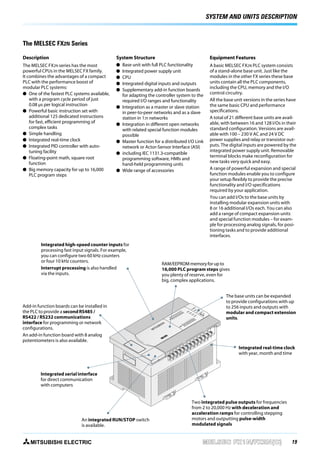
1. SYSTEM AND UNITS DESCRIPTION
The MELSEC FX2N Series
Description
System Structure
The MELSEC FX2N series has the most
powerful CPUs in the MELSEC FX family.
It combines the advantages of a compact
PLC with the performance boost of
modular PLC systems:
Ȝ One of the fastest PLC systems available,
with a program cycle period of just
0.08 µs per logical instruction
Ȝ Powerful basic instruction set with
additional 125 dedicated instructions
for fast, efficient programming of
complex tasks
Ȝ Simple handling
Ȝ Integrated real-time clock
Ȝ Integrated PID controller with autotuning facility
Ȝ Floating-point math, square root
function
Ȝ Big memory capacity for up to 16,000
PLC program steps
Ȝ
Ȝ
Ȝ
Ȝ
Ȝ
Ȝ
Integrated high-speed counter inputs for
processing fast input signals. For example,
you can configure two 60 kHz counters
or four 10 kHz counters.
Interrupt processing is also handled
via the inputs.
PO
W
ER
6
X1
4
X1
2
X1
0
X1
X6
IN
X4
X2
M
IT
SU
BI
SH
I
Add-in function boards can be installed in
the PLC to provide a second RS485 /
RS422 / RS232 communications
interface for programming or network
configurations.
An add-in function board with 8 analog
potentiometers is also available.
A basic MELSEC FX2N PLC system consists
of a stand-alone base unit. Just like the
modules in the other FX series these base
units contain all the PLC components,
including the CPU, memory and the I/O
control circuitry.
All the base unit versions in the series have
the same basic CPU and performance
specifications.
A total of 21 different base units are available, with between 16 and 128 I/Os in their
standard configuration. Versions are available with 100 – 230 V AC and 24 V DC
power supplies and relay or transistor outputs. The digital inputs are powered by the
integrated power supply unit. Removable
terminal blocks make reconfiguration for
new tasks very quick and easy.
A range of powerful expansion and special
function modules enable you to configure
your setup flexibly to provide the precise
functionality and I/O specifications
required by your application.
You can add I/Os to the base units by
installing modular expansion units with
8 or 16 additional I/Os each. You can also
add a range of compact expansion units
and special function modules – for example for processing analog signals, for positioning tasks and to provide additional
interfaces.
RAM/EEPROM memory for up to
16,000 PLC program steps gives
you plenty of reserve, even for
big, complex applications.
R
U
N
Ȝ
BA
T
PR T.V
O
CP G
U E
E
Ȝ
0
10 1
11 2
12 3
13 4
14 5
15 6
16 7
17
Ȝ
0
10 1
11 2
12 3
13 4
14 5
15 6
16 7
17
Ȝ
Equipment Features
Base unit with full PLC functionality
Integrated power supply unit
CPU
Integrated digital inputs and outputs
Supplementary add-in function boards
for adapting the controller system to the
required I/O ranges and functionality
Integration as a master or slave station
in peer-to-peer networks and as a slave
station in 1:n networks
Integration in different open networks
with related special function modules
possible
Master function for a distributed I/O Link
network or Actor-Sensor Interface (ASI)
including IEC 1131.3-compatible
programming software, HMIs and
hand-held programming units
Wide range of accessories
X0
M
CO
T
OU
0
Y1
M3
CO
Y2
1
YO Y
M1
CO
Y3
Y6
Y5
Y4
M2
CO
2
Y1
1
Y1
3
Y1
6
Y1
5
4
Y1
Y1
M4
CO
The base units can be expanded
to provide configurations with up
to 256 inputs and outputs with
modular and compact extension
units.
7
Y1
Y7
Integrated real-time clock
with year, month and time
Integrated serial interface
for direct communication
with computers
An integrated RUN/STOP switch
is available.
MITSUBISHI ELECTRIC
Two integrated pulse outputs for frequencies
from 2 to 20,000 Hz with deceleration and
acceleration ramps for controlling stepping
motors and outputting pulse-width
modulated signals
MELSEC FX1N/FX2N(C)
19
2. SYSTEM AND UNITS DESCRIPTION
Description of Units
˾ FX1N Series
Protective cover
Terminals for
digital inputs
Finger protection
Connection of the
power supply
Fixing hole
Extension bus
RUN/STOP switch
Slot for memory
cassettes
2 analog potentiometers
Connection for
programming units
Terminals for
service voltage source
Terminals for
digital outputs
100-240
VAC
S/S
L
N
X1
X0
X3
X2
X5
X4
X6
X15
X7 X11 X13
X10 X12 X14
LEDs for indicating
the input status
0 1 2 3
4 5 6 7
8 9 10 11
12 13 14 15
IN
POWER
RUN
ERROR
LEDs for indicating the
operating status
FX1N-24MR
OUT
0 1 2 3
4 5 6 7
10 11
Y6 Y10
Y5
Y3
Y2
Y1
Y11
Y0
0V
COM4 Y7
COM2 COM3 Y4
24+ COM0 COM1
24MR
-ES/UL
MITSUBISHI
LEDs for indicating
the output status
Housing cover
Lid
Finger protection
Protective cover
˾ FX2N Series
Connection of the
power supply
Fixing hole
Extension connector
for adapter units
Back-up battery
Connection for
programming units
RUN/STOP switch
Detachable terminal strip
for digital outputs
Slot for memory
cassettes
Detachable terminal strip
for digital inputs
LEDs for indicating
the input status
LEDs for indicating the
operating status
Connection for extensions
Protective cover for the
extension bus
LEDs for indicating
the output status
Protective cover
Housing cover
MITSUBISHI ELECTRIC
MELSEC FX1N/FX2N(C)
21
3. SYSTEM DATA
Environmental Specifications
General specifications
Data
Ambient temperature
þ FX1N þ FX2N þ FX2NC
0 – 55 °C
Operating temperature
0 – 55 °C
Storage temperature
-20 – +70 °C
Service power supply
24 V DC, 400 mA (FX1N); 250/460 mA (FX2N/FX2NC) ripple ratio at maximum load: ≤ ±5 %
Protection
IP 20
Noise durability
1000 Vpp with noise generator; 1 ms at 30 – 100 Hz
Dielectric withstand voltage
1,500 V AC, 1 min.
Ambient relative humidity
35 – 85 % (non-condensing)
Shock resistance
FX1N: 15 G (3 times in 3 directions) for 11 ms; FX2N: 10 G (3 times in 3 directions)
Vibration resistance
FX1N: 1 G (resistance to vibrations from 57–150 Hz for 80 minutes along all 3 axes); 0.5 G for DIN rail mounting
FX2N/FX2NC: 2 G (resistance to vibrations from 10 – 55 Hz for 2 hours along all 3 axes; 0.5 G for DIN rail mounting
Insulation resistance
500 V DC, 5 MΩ
Ground
Class 3
Fuse
Up to FX1N-24˿˿: 1 A; from FX1N-40˿˿: 3 A; from FX2N-32˿˿: 3.15 A; from FX2N-48˿˿: 5 A; FX2NC-16MR-T-DS: 2.5 A; FX2NC-˿˿MT-DSS: 3.15 A
Environment
Avoid environments containing corrosive gases, install in a dust-free location.
Certifications
FX1N: UL/CSA/CE/DNV/LR (summer 2003: RINA/BV/GL/ECE); FX2N: UL/CSA/CE/DNV/LR/GL/RINA (summer 2003: ECE); FX2NC: UL/CSA/CE (summer 2003: ECE)
General Specifications
System specifications
þ FX1N þ FX2N þ FX2NC
FX1N
FX2N/FX2NC
I/O points (addresses)
128 (+4 optional)
256
Address range
Max. 84 inputs X0–X123, max. 64 outputs Y0–Y77
Max. 248 inputs X0–X367, max. 248 outputs Y0–Y367
Program memory
8,000 steps EEPROM (internal),
exchangeble EEPROM for easy program exchange
8,000 steps RAM (internal),
4,000 steps EPROM/EEPROM cassettes (optional),
16,000 steps RAM cassettes (optional),
16,000 steps EEPROM cassettes (optional)
Cycle period
0.55 – 1.0 µs /logical instruction
0.08 µs / logical instruction
Number of instructions
29 sequence instructions, 2 step ladder instructions,
89 applied instructions
27 sequence instructions, 2 step ladder instructions, 18 verify instructions,
107 applied instructions
Programming language
Step ladder, instruction list, SFC
Step ladder, instruction list, SFC
Program execution
Cyclical execution, refresh mode processing
Cyclical execution, refresh mode processing
Program protection
Password protection with 3 protection levels
Password protection with 3 protection levels
Internal relays
1,536
3,072
Special relays
256
256
Step ladder
1,000
1,000
Timer
256
256
Ext. preset value via potentiometer
2
—
Counter
235
235
High-speed counter
6 single phase inputs (max. 60 kHz), 2 double phase inputs (max. 30 kHz)
6 single phase inputs (max. 60 kHz), 2 double phase inputs (max. 30 kHz)
Real-time clock
Year, month, day, hour, minut, second, weekday
Year, month, day, hour, minut, second, weekday (FX2NC optionally)
Data register
8,000
8.000
File register
Max. 7,000 (parameter editable), Total registers = 8,000
Max . 7,000 (parameter editable), Total registers = 8,000
Index register
16
16
Special register
256
256
Pointer
128
128
Nestings
8
8
Program data
for further details refer to p. 72
Operands
Interrupt inputs
6
6
Constants
16 bits: K: -32768 to +32767, hex: 0–FFFF
32 bits: K: 2147483648 to +2147483647, hex: 0–FFFF FFFF
16 bits: K: -32768 to +32767, hex: 0–FFFF
32 bits: K: 2147483648 to +2147483647, hex: 0–FFFF FFFF
32 bits floating point: 0, ±1.175 x 10-38 to ±3.403 x 10-38
MITSUBISHI ELECTRIC
MELSEC FX1N/FX2N(C)
27
4. SPECIFICATIONS
˾ Base Units
¨ FX1N þ FX2N ¨ FX2NC
Base Units FX2N
BASICS
The FX2N series base units are available with 16, 32, 48, 64, 80 or
128 input/output points.
It is possible to choose between relay and transistor output type.
Special Features:
Ȝ Exchangeable interface modules for direct mounting into
Ȝ
Ȝ
Ȝ
Ȝ
Ȝ
FX2N-16
MR-DS
FX2N-16
MR-ES/UL
FX2N-16
MT-DSS
FX2N-16
MT-ESS/UL
FX2N-32
MR-DS
FX2N-32
MR-ES/UL
FX2N-32
MT-DSS
FX2N-32
MT-ESS/UL
16
—
Hz —
24 V
25 W
—
—
ms 5
16
100–240 V
50/60 (±10 %)
—
30 VA
40 A < 5 ms
60 A < 5 ms
10
16
—
—
24 V
25 W
—
—
5
16
100–240 V
50/60 (±10 %)
—
30 VA
40 A < 5 ms
60 A < 5 ms
10
32
—
—
24 V
25 W
—
—
5
32
100–240 V
50/60 (±10 %)
—
40 VA
40 A < 5 ms
60 A < 5 ms
10
32
—
—
24 V
25 W
—
—
5
32
100–240 V
50/60 (±10 %)
—
40 VA
40 A < 5 ms
60 A < 5 ms
10
mA —
250
—
250
—
250
—
250
mA 290
290
290
290
290
290
290
290
8
mA 7 / 5
8
7/5
8
7/5
8
7/5
16
7/5
16
7/5
16
7/5
16
7/5
mA 4.5 / 3.5
4.5 /3.5
4.5 /3.5
4.5 / 3.5
4.5 / 3.5
4.5 / 3.5
4.5 / 3.5
4.5 / 3.5
Specifications
Electrical data
Integrated inputs/outputs
AC range (+10%,-15%)
Power
Frequency at AC
supply
DC range (+20 %, -30 %)
Max. input apparent power
AC 100 V
Inrush
current at ON AC 200 V
Allowable momentary power failure time
External service power supply
(24 V DC)
Power supply int. bus (5 V DC)
Inputs
Integrated inputs
Input current X0→X7 / X10→∞
Min. current for logical 1
X0→X7 / X10→∞
Max. current for logical 0
Isolation
Response time
Outputs
Integrated outputs
Output type
ON voltage (max.)
Max. output - per output
current
- per group*
Max. switching - inductive load
power
- lamp load
Response time
Life of contacts (switching times)
Mechanical data
Weight
Dimensions (W x H x D)
Order information
ቢ for Y0 and Y1 = 0.3 A; all others 0.5 A
a base unit
Standard programming unit interface
LEDs for indicating the input and output status
Detachable terminal blocks
Slot for memory cassettes for up to 16 k steps PLC program
Integrated real-time clock
mA 1.5
1.5
1.5
1.5
1.5
1.5
1.5
1.5
Photocoupler isolation between input terminals and PC power for all base units.
For all base units of the MELSEC FX2N series: 10 ms (at time of shipment), partly adjustable between 0 and 15 ms (REFF, FNC51 = 0 – 60 ms)
A
A
W
W
ms
8
8
8
8
16
16
Relay
Relay
Transitor
Transistor
Relay
Relay
Generally for relay version: < 250 V AC, < 30 V DC; for transistor version: 5 – 30 V DC
2
2
0.5 / 0.3ቢ
0.5 / 0.3ቢ
2
2
ባ
8
8
0.8 / 1.6
0.8 / 1.6ባ
8
8
80
80
12
12
80
80
100
100
1.5
1.5
100
100
10
10
< 0.2
< 0.2
10
< 0.2
For all base units of the MELSEC FX2N series: 3,000,000 at 20 VA; 1,000,000 at 35 VA; 200,000 at 80 VA
kg 0.6
mm 130 x 90 x 87
Art. no. 141270
16
Transistor
16
Transistor
0.5 / 0.3ቢ
0.8 / 1.6ባ
12
1.5
< 0.2
0.5 / 0.3ቢ
0.8 / 1.6ባ
12
1.5
< 0.2
0.6
130 x 90 x 87
0,6
130 x 90 x 87
0.6
130 x 90 x 87
0.65
150 x 90 x 87
0.65
150 x 90 x 87
0.65
150 x 90 x 87
0.65
150 x 90 x 87
141271
103689
141272
141273
141274
141275
141276
ባ 0.8 for 4 per group and 1.6 for 8 per group
* This limitation applies only per reference terminal for each group, 4 and 8 outputs for relays and 2 and 4 outputs for transistors. Please observe the terminal assignments for the group identification.
30
MELSEC FX1N/FX2N
MITSUBISHI ELECTRIC