Weitere ähnliche Inhalte
Ähnlich wie 0071549226 ar012 (20)
Mehr von Zakee Kazmee (20)
0071549226 ar012
- 1. Source: GEOTECHNICAL ENGINEERING
12 Soil Consistency
and Engineering
Classification
12.1 CLASSIFICATION AND SOIL BEHAVIOR
12.1.1 Classification and Engineering Properties
Soil properties that are of most concern in engineering are strength and volume
change under existing and future anticipated loading conditions. Various tests
have been devised to determine these behaviors, but the tests can be costly and
time-consuming, and often a soil can be accepted or rejected for a particular use
on the basis of its classification alone.
For example, an earth dam constructed entirely of sand would not only leak, it
would wash away. Classification can reveal if a soil may merit further
investigation for founding a highway or building foundation, or if it should be
rejected and either replaced, modified, or a different site selected. Important clues
can come from the geological and pedological origin, discussed in preceding
chapters. Another clue is the engineering classification, which can be useful even if
the origin is obscure or mixed, as in the case of random fill soil.
12.1.2 Classification Tests
Engineering classifications differ from scientific classifications because they focus
on physical properties and potential uses. Two tests devised in the early 1900s by a
Swedish soil scientist, Albert Atterberg, are at the heart of engineering
classifications. The tests are the liquid limit or LL, which is the moisture
content at which a soil become liquid, and the plastic limit or PL, which is
the moisture content at which the soil ceases to become plastic and crumbles in
the hand.
Both limits are strongly influenced by the clay content and clay mineralogy,
and generally as the liquid limit increases, the plastic limit tends to decrease.
246 Downloaded from Digital Engineering Library @ McGraw-Hill (www.digitalengineeringlibrary.com)
Copyright © 2007 The McGraw-Hill Companies. All rights reserved.
Any use is subject to the Terms of Use as given at the website.
- 2. Soil Consistency and Engineering Classification
Soil Consistency and Engineering Classification 247
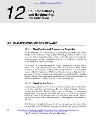
Figure 12.1
Schematic
representation of
transitions between
solid, plastic, and
viscous liquid
behaviors defined
by liquid and
plastic limits. These
tests are basic to
engineering
classifications and
emphasize
influences of clay
mineralogy and
capillarity.
The numerical difference between the two limits therefore represents a range in
moisture contents over which the soil is plastic, and is referred to as the plasticity
index or PI. By definition,
PI ¼ LL À PL ð12:1Þ
where PI is the plasticity index and LL and PL the liquid limit and plastic limit,
respectively. This relationship is shown in Fig. 12.1. Because the plasticity index
is a difference in percentages and not in itself a percentage, it is expressed as a
number and not a percent. Also shown in the figure is the shrinkage limit, which is
discussed later in the chapter.
12.1.3 Preparation of Soil for Testing
As discussed in relation to clay mineralogy, drying a soil can change its
adsorptive capacity for water and therefore can change the liquid and plastic
limits. If the soil contains the clay mineral halloysite, dehydration from
air-drying is permanent, so to obtain realistic data the soil must not be dried
prior to testing. A similar change can occur in soils that have a high content of
organic matter.
Air-drying nevertheless is still an approved method because it is more convenient
for storing soil samples and for dry sieving, because only the portion of a soil
passing the No. 40 (425 mm) sieve is tested. Also, many existing correlations were
made on the basis of tests of air-dried samples. If a soil has been air-dried it should
be mixed with water for 15 to 30 minutes, sealed and stored overnight, and
re-mixed prior to testing. Details are in ASTM D-4318.
Downloaded from Digital Engineering Library @ McGraw-Hill (www.digitalengineeringlibrary.com)
Copyright © 2007 The McGraw-Hill Companies. All rights reserved.
Any use is subject to the Terms of Use as given at the website.
- 3. Soil Consistency and Engineering Classification
248 Geotechnical Engineering
12.1.4 Liquidity Index
The liquidity index indicates how far the natural soil moisture content has
progressed between the plastic and liquid limits. If the soil moisture content is at
the plastic limit, the liquidity index is 0; if it is at the liquid limit, it is 1.0.
The formula for the liquidity index is
w À PL
LI ¼ ð12:2Þ
LL À PL
where LI is the liquidity index, w is the soil moisture content, PL is the plastic limit,
and LL is the liquid limit. The liquidity index also is called the relative consistency.
12.2 MEASURING THE LIQUID LIMIT
12.2.1 Concept
The concept of the liquid limit is simple: keep adding water to a soil until it flows,
and measure the moisture content at that point by oven-drying a representative
sample. Two difficulties in application of this concept are (1) the change from
plastic to liquid behavior is transitional, and (2) flow can be prevented by
thixotropic setting.
In order to overcome these limitations, Atterberg suggested that wet soil be placed
in a shallow dish, a groove cut through the soil with a finger, and the dish
jarred 10 times to determine if the groove closes. While this met the challenge
of thixotropy, it also introduced a personal factor. Professor A. Casagrande
of Harvard University therefore adapted a cog arrangement invented by
Leonardo da Vinci, such that turning a crank drops a shallow brass cup
containing wet soil 10 mm onto a hard rubber block, shown in Fig. 12.2.
The crank is turned at 2 revolutions per second, and the groove is standardized.
Casagrande defined the liquid limit as the moisture content at which the groove
would close after 25 blows, which increased the precision of the blow count
determination. Different amounts of water are added to a soil sample and stirred
in, and the test repeated so that the blow counts bracket the required 25. As it is
unlikely that the exact number will be achieved at any particular moisture content,
a graph is made of the logarithm of the number of blows versus the moisture
content, a straight line is drawn, and the liquid limit read from the graph where
the line intersects 25 blows (Fig. 12.3).
12.2.2 Procedure for the Liquid Limit Test
A quantity of soil passing the No. 40 sieve is mixed with water to a paste
consistency and stored overnight. It is then re-mixed and placed in a standardized
Downloaded from Digital Engineering Library @ McGraw-Hill (www.digitalengineeringlibrary.com)
Copyright © 2007 The McGraw-Hill Companies. All rights reserved.
Any use is subject to the Terms of Use as given at the website.
- 4. Soil Consistency and Engineering Classification
Soil Consistency and Engineering Classification 249
Figure 12.2
Casagrande-da
Vinci liquid limit
device.
Figure 12.3
Semilogarithmic
plot for
determining a soil
liquid limit.
round-bottomed brass cup, and the surface is struck off with a spatula so
that the maximum thickness is 10 mm. The soil pat then is divided into two
segments by means of a grooving tool of standard shape and dimensions.
The brass cup is mounted in such a way that, by turning a crank, it can be
raised and allowed to fall sharply onto a hard rubber block or base. The shock
produced by this fall causes the adjacent sides of the divided soil pat to flow
together. The wetter the mixture, the fewer shocks or blows will be required
to cause the groove to close, and the drier the mixture, the greater will be the
number of blows.
The number of blows required to close the groove in the soil pat is determined
at three or more moisture contents, some above the liquid limit and some
below it. The logarithm of the number of blows is plotted versus the moisture
content and a straight line is drawn through the points, as shown in Fig. 12.3.
The moisture content at which 25 blows cause the groove to close is defined
Downloaded from Digital Engineering Library @ McGraw-Hill (www.digitalengineeringlibrary.com)
Copyright © 2007 The McGraw-Hill Companies. All rights reserved.
Any use is subject to the Terms of Use as given at the website.
- 5. Soil Consistency and Engineering Classification
250 Geotechnical Engineering
as the liquid limit. Tests usually are performed in duplicate and average results
reported.
A ‘‘one-point’’ test may be used for routine analyses, in which the number of
blows is between 20 and 30 and a correction that depends on the departure
from 25 is applied to the moisture content. See AASHTO Specification T-89 or
ASTM Specification D-423 for details of the liquid limit test.
12.3 MEASURING THE PLASTIC LIMIT
12.3.1 Concept
Soil with a moisture content lower than the liquid limit is plastic, meaning that
it can be remolded in the hand. An exception is clean sand, which falls apart on
remolding and is referred to as ‘‘nonplastic.’’ It is the plasticity of clays that allows
molding of ceramics into statues or dishes. At a certain point during drying,
the clay can no longer be remolded, and if manipulated, it breaks or crumbles;
it is a solid. The moisture content at which a soil no longer can be remolded
is the plastic limit, or PL.
The standard procedure used to determine the plastic limit of a soil is deceptively
simple. The soil is rolled out into a thread, and if it does not crumble it is then
balled up and rolled out again, and again, and again . . . until the thread falls apart
during remolding. It would appear that a machine might be devised to perform
this chore, but several factors make the results difficult to duplicate. First, the soil
is continuously being remolded, and second, it gradually is being dried while being
remolded. A third factor is even more difficult—the effort required to remold the
soil varies greatly depending on the clay content and clay mineralogy. Despite
these difficulties and the lack of sophistication, the precision is comparable to or
better than that of the liquid limit test.
12.3.2 Details of the Plastic Limit Test
The plastic limit of a soil is determined in the laboratory by a standardized
procedure, as follows. A small quantity of the soil-water mixture is rolled out with
the palm of the hand on a frosted glass plate or on a mildly absorbent surface such
as paper until a thread or worm of soil is formed. When the thread is rolled to a
diameter of 3 mm (1 in.), it is balled up and rolled out again, the mixture gradually
8
losing moisture in the process. Finally the sample dries out to the extent that it
becomes brittle and will no longer hold together in a continuous thread. The
moisture content at which the thread breaks up into short pieces in this rolling
process is considered to be the plastic limit (Fig. 12.4). The pieces or crumbs
therefore are placed in a small container for weighing, oven-drying, and
re-weighing. Generally at least two determinations are made and the results
Downloaded from Digital Engineering Library @ McGraw-Hill (www.digitalengineeringlibrary.com)
Copyright © 2007 The McGraw-Hill Companies. All rights reserved.
Any use is subject to the Terms of Use as given at the website.
- 6. Soil Consistency and Engineering Classification
Soil Consistency and Engineering Classification 251
Figure 12.4
The plastic limit
test. As the soil
thread crumbs,
pieces are
collected in a metal
container for oven-
drying to determine
the moisture
content.
averaged. See AASHTO Specification T-90 or ASTM Specification D-424 for
details of the plastic limit test.
12.4 DIRECT APPLICATIONS OF LL AND PL TO FIELD SITUATIONS
12.4.1 When a Soil Moisture Content Exceeds
the Plastic Limit
The liquid limit and plastic limit tests are more diagnostic than descriptive of
soil behavior in the field because the tests involve continual remolding. However,
there are some important situations where remolding occurs more or less con-
tinuously in the field. One example is soil in the basal zone of a landslide. As a
landslide moves, it shears and mixes the soil. This mixing action can occur if the
soil moisture exceeds the plastic limit. If through chemical treatment such as with
drilled lime (quicklime) the plastic limit is increased, the landslide stops.
12.4.2 When a Soil Moisture Content Exceeds the
Liquid Limit
Exceeding the soil liquid limit in the field can generate harmful and potentially
devastating results, as the soil may appear to be stable and then when disturbed
can suddenly break away, losing its thixotropic strength and becoming
transformed into a rapid churning, flowing mudslide that takes everything in its
way. The rate of sliding depends on the slope angle and viscosity of the mud; the
lower the viscosity and steeper the slope, the faster the slide. The most devastating
mudslides in terms of loss of life therefore occur in mountainous terrain where the
mud moves faster than people can get out of the way and escape almost certain
Downloaded from Digital Engineering Library @ McGraw-Hill (www.digitalengineeringlibrary.com)
Copyright © 2007 The McGraw-Hill Companies. All rights reserved.
Any use is subject to the Terms of Use as given at the website.
- 7. Soil Consistency and Engineering Classification
252 Geotechnical Engineering
death. Quick clays that appear stable can turn into a soup that can be poured
like pancake batter.
12.4.3 Liquefaction
Another example where a liquid limit may be exceeded is when a saturated sand
or silt suddenly densifies during an earthquake so that all of its weight goes to
pore water pressure. This is liquefaction, which can cause a sudden and complete
loss of shear strength so that landslides develop and buildings may topple. The
consequences, diagnosis, and prevention of liquefaction are discussed in more
detail in a later chapter.
12.5 THE PLASTICITY INDEX
12.5.1 Concept
The plasticity index, or PI, is the numerical difference between the liquid and
plastic limit moisture contents. Whereas the two limits that are used to define a PI
are directly applicable to certain field conditions, the plasticity index is mainly
used to characterize a soil, where it is a measure of cohesive properties. The
plasticity index indicates the degree of surface chemical activity and hence the
bonding properties of clay minerals in a soil. The plasticity index is used along
with the liquid limit and particle size gradation to classify soils according to their
engineering behavior.
An example of a direct application of the plasticity index is as an indicator of the
suitability of the clay binder in a soil mixture used for pavement subgrades, base
courses, or unpaved road surfaces. If the PI of the clay fraction of a sand-clay or
clay-gravel mixture is too high, the exposed soil tends to soften and become
slippery in wet weather, and the road may rut under traffic. On the other hand,
if the plasticity index is too low, the unpaved road will tend to ‘‘washboard’’ in
response to resonate bouncing of wheels of vehicular traffic. Such a road will
abrade under traffic and antagonize the public by producing air-borne dust in
amounts that have been measured as high as one ton per vehicle mile per day per
year. That is, a rural unpaved road carrying an average of 40 vehicles per day can
generate up to 40 tons of dust per mile per year. Most collects in roadside ditches
that periodically must be cleaned out.
12.5.2 A PI of Zero
Measurements of the LL and PL may indicate that a soil has a plasticity
index equal to zero; that is, the numerical values of the plastic limit and the
liquid limit may be the same within the limits of accuracy of measurement.
Soil with a plasticity index of zero therefore still exhibits a slight plasticity, but
Downloaded from Digital Engineering Library @ McGraw-Hill (www.digitalengineeringlibrary.com)
Copyright © 2007 The McGraw-Hill Companies. All rights reserved.
Any use is subject to the Terms of Use as given at the website.
- 8. Soil Consistency and Engineering Classification
Soil Consistency and Engineering Classification 253
the range of moisture content within which it exhibits the properties of a plastic
solid is not measured by the standard laboratory tests.
12.5.3 Nonplastic Soils
Drying and manipulating a truly nonplastic soil such as a clean sand will cause it
to abruptly change from a liquid state to an incoherent granular material that
cannot be molded. If it is not possible to roll soil into a thread as small as 3 mm in
diameter, a plastic limit cannot be determined and the soil is said to be nonplastic,
designated as NP in test reports.
12.6 ACTIVITY INDEX AND CLAY MINERALOGY
12.6.1 Definition of Activity Index
The activity index was defined by Skempton to relate the PI to the amount of clay
in a soil, as an indication of the activity of the clay and therefore the clay mineral-
ogy: the higher the activity index, or AI, the more active the clay. The activity index
was defined as the PI divided by the percent 0.002 mm (or 2 mm) clay:
PI
AI ¼ ð12:3Þ
C002
where AI is the activity index, PI the plasticity index, and C002 the percent 2 mm
clay determined from a particle size analsysis. The basis for this relationship
is shown in Fig. 12.5.
12.6.2 Relation to Clay Mineralogy
The relationship between activity index and clay mineralogy is shown in
Table 12.1. Clay mineral mixtures and interlayers have intermediate activities.
Data in the table also show how the activity of smectite is strongly influenced by
the adsorbed cation on the plasticity index.
12.6.3 Modified Activity Index
The linear relationships in Fig. 12.5 do not necessarily pass through the origin.
This is shown in Fig. 12.6, where about 10 percent clay is required to generate
plastic behavior. This also has been found in other investigations (Chen, 1988).
It therefore is recommended that for silty soils eq. (12.3) be modified as follows:
PI
A¼ ð12:4Þ
C002 À k
where A is the activity, C is the percent of the soil finer than 0.002 mm, and
k is a constant that depends on the soil type. For silty soils k ¼ 10. If this equation
Downloaded from Digital Engineering Library @ McGraw-Hill (www.digitalengineeringlibrary.com)
Copyright © 2007 The McGraw-Hill Companies. All rights reserved.
Any use is subject to the Terms of Use as given at the website.
- 9. Soil Consistency and Engineering Classification
254 Geotechnical Engineering
Figure 12.5
Linear relations
between PI and
percent clay.
Ratios were
defined by
Skempton (1953)
as activity indices,
which are shown
in parentheses.
The Shellhaven
soil clay probably
is smectite.
Table 12.1 Naþ smectite (montmorillonite) 3–7
Activity indices of Ca2þ smectite (montmorillonite) 1.2–1.3
selected clay Illite 0.3–0.6
minerals (after Grim, Kaolinite, poorly crystallized 0.3–0.4
1968) Kaolinite, well crystallized 50.1
is applied to the data in Fig. 12.6 with k ¼ 10, then A ¼ 1.23 Æ 0.04 where
the Æ value is the standard error for a number of determinations n ¼ 81.
This identifies the clay mineral as calcium smectite, which is confirmed by X-ray
diffraction.
12.7 LIQUID LIMIT AND COLLAPSIBILITY
12.7.1 Concept
A simple but effective idea was proposed in 1953 by a Russian geotechnical
engineer, A. Y. Denisov, and later introduced into the U.S. by Gibbs and Bara of
Downloaded from Digital Engineering Library @ McGraw-Hill (www.digitalengineeringlibrary.com)
Copyright © 2007 The McGraw-Hill Companies. All rights reserved.
Any use is subject to the Terms of Use as given at the website.
- 10. Soil Consistency and Engineering Classification
Soil Consistency and Engineering Classification 255
Figure 12.6
Data suggesting a
modification to
eq. (12.3) for silty
soil.
the U.S. Bureau of Reclamation. Denisov argued that if the moisture content
upon saturation exceeds the liquid limit, the soil should be collapsible—that is,
it should collapse and densify under its own weight if it ever becomes saturated.
The most common collapsible soil is loess, which is a widespread surficial deposit
in the U.S., Europe, and Asia. Because loess increases in density with depth
and with distance from a source, only the upper material close to a source may be
collapsible, so this is a valuable test.
12.7.2 Moisture Content Upon Saturation
The soil unit weight and specific gravity of the soil mineral grains are required
to calculate the moisture content upon saturation, which are entered into the
following equations:
SI: ws ¼ 100ð9:807=d À 1=GÞ ð12:5Þ
English: ws ¼ 100ð62:4=d À 1=GÞ ð12:5aÞ
where ws is the percent moisture at saturation, d is the dry unit weight in kN/m3
or lb/ft3, and G is the specific gravity of the soil minerals. Solutions of this
equation with G ¼ 2.70 are shown in Fig. 12.7.
12.8 CONSISTENCY LIMITS AND EXPANSIVE SOILS
12.8.1 Measuring Expandability
Expandability can be determined with a consolidometer, which is a device that was
developed to measure compression of soil but also can be used to measure
expansion under different applied loads. Samples are confined between porous
ceramic plates, loaded vertically, wet with water, and the amount of expansion
measured. An abbreviated test measures expansion under only applied pressures
that can simulate a floor or a foundation load.
Downloaded from Digital Engineering Library @ McGraw-Hill (www.digitalengineeringlibrary.com)
Copyright © 2007 The McGraw-Hill Companies. All rights reserved.
Any use is subject to the Terms of Use as given at the website.
- 11. Soil Consistency and Engineering Classification
256 Geotechnical Engineering
Figure 12.7
Denisov criterion
for collapsibility
with G ¼ 2.70.
Data are for loess
at 3, 40, and 55 ft
(1, 12, and 16.8 m)
depths in Harrison
County, Iowa. The
deepest soil was
mottled gray,
suggesting a
history of wet
conditions, and is
indicated to be
noncollapsible.
Many investigations have been made relating expansion to various para-
meters, including activity, percent finer than 0.002 mm, percent finer than
0.001 mm, plasticity index, and liquid limit. For the most part the studies
have used artificially prepared soil mixtures with varying amounts of different
clay minerals.
12.8.2 Influence of Surcharge Pressure
Generally the higher the vertical surcharge pressure, the lower the amount of
expansion. This leads to a common observation in buildings founded on
expansive clay: floors in contact with the soil are lifted more than foundations
that are supporting bearing walls and columns and therefore are more heavily
loaded. Partition walls that are not load-bearing are lifted with the floor.
12.8.3 Lambe’s PVC Meter
A rapid method for measuring clay expandability was developed by T. W. Lambe
and his coworkers at MIT. In this device, soil expands against a spring-loaded
plate and the expansion is measured. Because the vertical stress increases as the
soil expands, results are useful for classification but do not directly translate into
expansion amounts that may be expected in the field.
12.8.4 Influence of Remolding
Chen (1988) emphasizes that expansion is much lower for undisturbed than
for disturbed soil samples subjected to the same treatment, indicating an impor-
tant restraining influence from soil fabric. Therefore the expansive clay that
is inadvertently used for fill soil, as sometimes happens, may expand much
Downloaded from Digital Engineering Library @ McGraw-Hill (www.digitalengineeringlibrary.com)
Copyright © 2007 The McGraw-Hill Companies. All rights reserved.
Any use is subject to the Terms of Use as given at the website.
- 12. Soil Consistency and Engineering Classification
Soil Consistency and Engineering Classification 257
more than if the clay were not disturbed. The reason for this has not been
investigated, but an argument may be made for a time-related cementation effect
of edge-to-face clay particle bonding, which would prevent water from entering
and separating the clay layers.
12.8.5 Relation to PI
Figure 12.8 shows the conclusions of several researchers who related clay expand-
ability to the plasticity index or PI. Curves A and B show results for remolded
samples, and curves C and D are from undisturbed samples where surcharges were
applied to more or less simulate floor and foundation loads, respectively. It will be
seen that the lowest expandability is shown by curve D, which is for undisturbed
soil under the foundation load.
12.8.6 Relation to Moisture Content
Generally expansion pressure decreases as the soil moisture content increases,
and expansion stops when the smectite clay is fully expanded. This depends on the
relative humidity of the soil air and occurs well below the point of saturation of
the soil itself. This is illustrated in Fig. 12.9, where seasonal volume change
occurs between 30 and 70 percent saturation. Expansion will not occur in a clay
that already is wet, which is not particularly reassuring because damaging
shrinkage still can occur if and when the clay dries out.
Figure 12.8
Data indicating that
remolding and a
loss of structure
greatly increase
swelling pressures.
All but curve D,
which has a
surcharge pressure
of 1000 lb/ft2
(44 kPa) have a
surcharge
pressure of 1 lb/in.2
(6.9 kPa).
(Modified from
Chen, 1988.)
Downloaded from Digital Engineering Library @ McGraw-Hill (www.digitalengineeringlibrary.com)
Copyright © 2007 The McGraw-Hill Companies. All rights reserved.
Any use is subject to the Terms of Use as given at the website.
- 13. Soil Consistency and Engineering Classification
258 Geotechnical Engineering
Figure 12.9
Seasonal volume
changes in Poona
clay, India. Left
graph shows that
expandability is
limited to the upper
meter despite
deeper variations
in moisture
content. (From
Katti and Katti,
1994.)
12.8.7 Summary of Factors Influencing Expandability
The amount of expansion that can be anticipated depends on at least seven
variables: (1) clay mineralogy, and (2) clay content, both of which are reflected in
the consistency limits; (3) existing field moisture content; (4) surcharge pressure;
(5) whether or not the soil is remolded; (6) thickness of the expanding layer; and
(7) availability of water.
12.8.8 Thickness of the Active Layer
One of the most extensive expansive clay areas in the world is in India, but
detailed field investigations indicate that only about the upper 90 cm (3 ft) of the
expansive soil actually experiences seasonal volume changes. Below that depth
the clay is volumetrically stable, even though, as seen in the second graph
of Fig. 12.9, the moisture content is not. As previously indicated, saturation is
not required for full expansion of Ca-smectite, which is the most common
expansive clay.
The surficial layer involved in seasonal volume change is called the active layer,
and determines the depth of shrinkage cracking and vertical mixing, which by
disrupting the soil structure tends to increase its expandability.
Example 12.1
Calculate the seasonal ground heave from data in Fig. 12.9.
Answer: If the soil is divided into three layers, 0–30, 30–60, and 60–90 cm, average increases
in density from the left-hand graph are approximately 0.5/1.22 ¼ 41%; 0.2/1.3 ¼ 15%; and
0.1/1.3 ¼ 8%, respectively. Multiplying these percentages by the layer thicknesses gives total
volume changes from the dry to the wet seasons of (0.41 þ 0.15 þ 0.08) Â 30 ¼ 19 cm
(7.5 in.). However, part of this will go toward closing open ground cracks, in which case
one-third of the volume change will be directed vertically, about 6 cm or 2.5 in. The answer
Downloaded from Digital Engineering Library @ McGraw-Hill (www.digitalengineeringlibrary.com)
Copyright © 2007 The McGraw-Hill Companies. All rights reserved.
Any use is subject to the Terms of Use as given at the website.
- 14. Soil Consistency and Engineering Classification
Soil Consistency and Engineering Classification 259
therefore is between 6 and 19 cm, depending on filling of the shrinkage cracks and
amount of lateral elastic compression of the soil.
12.8.9 Controlling Volume Change with a
Nonexpansive Clay (n.e.c.) Layer
One of the most significant discoveries for controlling expansive clay was by
Dr. R. K. Katti and his co-workers at the Indian Institute of Technology, Mumbai.
Katti’s group conducted extensive full-scale laboratory tests to confirm field
measurements, such as shown in Fig. 12.9, and found that expansion can be
controlled by a surficial layer of compacted non-expansive clay. A particularly
severe test for the design was the canal shown in Fig. 12.10. The most common
application of Katti’s method is to stabilize the upper meter (3 ft) of expansive
clay by mixing in hydrated lime, Ca(OH)2. If only the upper one-third, 30 cm
(1 ft), is stabilized, volume change will be (0.15 þ 0.08) Â 30 ¼ 7 cm (3 in.), a
reduction of about 60 percent. If the upper 60 cm (2 ft) is stabilized, the volume
change will be 0.08 Â 30 ¼ 2.4 cm (1 in.), a reduction of over 85 percent.
Stabilization to the full depth has been shown to eliminate volume change
altogether. The next question is, why?
An answer may be in the curves in Fig. 12.8, as a loss of clay structure greatly
increases clay expandability. As a result of shrink-swell cycling and an increase in
horizontal stress, expansive clays are visibly sheared, mixed, and remolded, so by
destroying soil structure expansion probably begets more expansion. According to
this hypothesis, substituting a layer of nonexpansive clay for the upper highly
expansive layer may help to preserve the structure and integrity of the underlying
layer. It was found that using a sand layer or a foundation load instead of densely
Figure 12.10
The Malaprabha
Canal in India was
successfully built
on highly
expansive clay
using Katti’s
method, by
replacing the upper
1 m of soil with
compacted
nonexpansive clay
(n.e.c.) to
replicate the
conditions shown
in Fig. 12.9 for the
underlying soil.
Downloaded from Digital Engineering Library @ McGraw-Hill (www.digitalengineeringlibrary.com)
Copyright © 2007 The McGraw-Hill Companies. All rights reserved.
Any use is subject to the Terms of Use as given at the website.
- 15. Soil Consistency and Engineering Classification
260 Geotechnical Engineering
compacted clay is less effective, perhaps because it interrupts the continuum (Katti
and Katti, 2005).
12.9 PLASTICITY INDEX VS. LIQUID LIMIT
12.9.1 Concept
The relationship between PI and LL reflects clay mineralogy and has an advan-
tage over the activity index because a particle size analysis is not required. Because
the liquid limit appears on both sides of the relationship, data can plot only within
a triangular area defined by the PL ¼ 0 line shown in Fig. 12.11.
12.9.2 The A-Line
A line that approximately parallels the PI versus LL plot for particular soil groups
is called the A-line, which was proposed by A. Casagrande and for the most part
separates soils with and without smectite clay minerals. However, the separation is
not always consistent, as can be seen in Fig. 12.11 where loess crosses the line.
At low clay contents loessial soils also are more likely to show collapse behavior
instead of expanding.
12.10 A SOIL CLASSIFICATION BASED ON THE A-LINE
12.10.1 Background
During World War II, Arthur Casagrande devised a simplified soil classification
system for use by the armed forces. The objective was a system that could be used
to classify soils from visual examination and liquid/plastic behavior. In 1952
Figure 12.11
Representative
relationships
between PI and
LL. (Adapted from
U.S. Dept. of
Interior Bureau of
Reclamation,
1974.)
Downloaded from Digital Engineering Library @ McGraw-Hill (www.digitalengineeringlibrary.com)
Copyright © 2007 The McGraw-Hill Companies. All rights reserved.
Any use is subject to the Terms of Use as given at the website.
- 16. Soil Consistency and Engineering Classification
Soil Consistency and Engineering Classification 261
the system was adopted for civilian uses by the U.S. Bureau of Reclamation and
the U.S. Army Corps of Engineers and became known as the Unified
Classification. The ASTM Designation is D-2487. The system applies not only
to fine-grained soils but also to sands and gravels, and is the most widely used
system for soil investigations for building foundations and tunneling.
12.10.2 ‘‘S’’ Is for Sand
One advantage of the Unified Classification system is its simplicity, as it uses
capital letters to represent particular soil properties: S stands for sand, G for
gravel, and C for clay. Because S already is used for sand, another letter, M, was
selected for silt, from the German word Moh.
A sand or gravel can either be well graded, W, or for poorly graded, designated by
P, respectively indicating broad or narrow ranges of particle sizes. Thus, SP is a
poorly graded sand, GW a well-graded gravel.
Fine-grained soils are characterized on the basis of liquid limit and the PI and
LL relationships to the A-line. A silt or clay with a liquid limit higher than
50 percent is designated by H, meaning high liquid limit, and if the data plot above
the A-line the soil is CH, clay with a high liquid limit. If the liquid limit is higher
than 50 percent and the data plot below the A-line, the designation is MH, silt
with a high liquid limit.
The Unified Classification system therefore distinguishes between silt and clay not
on the basis of particle size, but on relationships to the liquid limit and plasticity
index. In order to avoid confusion, clay and silt that are defined on the basis of
size now usually are referred to as ‘‘clay-size’’ or ‘‘silt-size’’ material.
If the silt or clay liquid limit is lower than 50, the respective designations are
ML and CL, silt with a low liquid limit or clay with a low liquid limit. However, if
the plasticity index is less than 4, silt dominates the soil behavior and the soil is
designated ML. This is shown in the graph in Table 12.2. Soils with a plasticity
index between 4 and 7 show properties that are intermediate and are designated
CL-ML.
12.10.3 Details of the Unified Classification System
Letter abbreviations for the various soil characteristics are as follows:
G ¼ Gravel O ¼ Organic
S ¼ Sand W ¼ Well graded
M ¼ Nonplastic or low plasticity P ¼ Poorly graded
C ¼ Plastic fines L ¼ Low liquid limit
Pt ¼ Peat, humus, swamp soils H ¼ High liquid limit
Downloaded from Digital Engineering Library @ McGraw-Hill (www.digitalengineeringlibrary.com)
Copyright © 2007 The McGraw-Hill Companies. All rights reserved.
Any use is subject to the Terms of Use as given at the website.
- 17. Soil Consistency and Engineering Classification
262 Geotechnical Engineering
Table 12.2
Unified soil classification system
Downloaded from Digital Engineering Library @ McGraw-Hill (www.digitalengineeringlibrary.com)
Copyright © 2007 The McGraw-Hill Companies. All rights reserved.
Any use is subject to the Terms of Use as given at the website.
- 18. Soil Consistency and Engineering Classification
Soil Consistency and Engineering Classification 263
Downloaded from Digital Engineering Library @ McGraw-Hill (www.digitalengineeringlibrary.com)
Copyright © 2007 The McGraw-Hill Companies. All rights reserved.
Any use is subject to the Terms of Use as given at the website.
- 19. Soil Consistency and Engineering Classification
264 Geotechnical Engineering
These letters are combined to define various groups as shown in Table 12.2.
This table is used to classify a soil by going from left to right and satisfying the
several levels of criteria.
12.10.4 Equivalent Names
Some equivalent names for various combined symbols are as follows. These
names are appropriate and should be used in reports that may be read by people
who are not familiar with the soil classification symbols. For example, describing
a soil as an ‘‘SC clayey sand’’ will be more meaningful than to only refer to it as
‘‘SC,’’ and illustrates the logic in the terminology. The meanings of the symbols
for coarse-grained soils are fairly obvious. Names used for fine-grained soils are as
follows:
CL ¼ lean clay CH ¼ fat clay
ML ¼ silt MH ¼ elastic silt
OL ¼ organic silt OH ¼ organic clay
If a fine-grained soil contains over 15 percent sand or gravel, it is referred to as
‘‘with sand or with gravel;’’ if over 30 percent, it is ‘‘sandy’’ or ‘‘gravelly.’’ If over
50 percent it goes into a coarse-grained classification. If a soil contains any
cobbles or boulders it is referred to as ‘‘with cobbles’’ or ‘‘with boulders.’’ Other
more detailed descriptors will be found in ASTM D-2487.
12.10.5 Detailed Descriptions
Descriptions of the various groups that may be helpful in classification are as
follows:
GW and SW
Soils in these groups are well-graded gravelly and sandy soils that contain less
than 5 percent nonplastic fines passing the No. 200 sieve. The fines that are
present do not noticeably affect the strength characteristics of the coarse-grained
fraction and must not interfere with its free-draining characteristic. In areas
subject to frost action, GW and SW soils should not contain more than about
3 percent of soil grains smaller than 0.02 mm in size.
GP and SP
GP and SP soils are poorly graded gravels and sands containing less than
5 percent of nonplastic fines. The soils may consist of uniform gravels, uniform
sands, or nonuniform mixtures of very coarse material and very fine sand with
intermediate sizes lacking, referred to as skip-graded, gap-graded, or step-graded.
GM and SM
In general, GM and SM soils are gravels or sands that contain more than
12 percent fines having little or no plasticity. In order to qualify as M, the
Downloaded from Digital Engineering Library @ McGraw-Hill (www.digitalengineeringlibrary.com)
Copyright © 2007 The McGraw-Hill Companies. All rights reserved.
Any use is subject to the Terms of Use as given at the website.
- 20. Soil Consistency and Engineering Classification
Soil Consistency and Engineering Classification 265
plasticity index and liquid limit plot below the A-line on the plasticity chart.
Because of separation of coarse particles gradation is less important, and both
well-graded and poorly graded materials are included in these groups. Some sands
and gravels in these groups may have a binder composed of natural cementing
agents, so proportioned that the mixture shows negligible swelling or shrinkage.
Thus, the dry strength is provided either by a small amount of soil binder or by
cementation of calcareous materials or iron oxide. The fine fraction of
noncemented materials may be composed of silts or rock-flour types having
little or no plasticity, and the mixture will exhibit no dry strength.
GC and SC
These groups consist of gravelly or sandy soils with more than 12 percent fines that
can exhibit low to high plasticity. The plasticity index and liquid limit plot above
the A-line on the plasticity chart. Gradation of these materials is not important, as
the plasticity of the binder fraction has more influence on the behavior of the soils
than does variation in gradation. The fine fraction is generally composed of clays.
Borderline G and S Classifications
It will be seen that a gap exists between the GW, SW, GP, and SP groups, which
have less than 5 percent passing the No. 200 sieve, and GM, SM, GC, and SC
soils, which have more than 12 percent passing the No. 200 sieve. Soils containing
between 5 and 12 percent fines are considered as borderline and are designated by
a dual symbol such as GW-GM if the soil is a well-graded gravel with a silt
component, or GW-GC if well-graded with a clay component. Many other dual
symbols are possible, and the meaning should be evident from the symbol. For
example, SP-SC is a poorly graded sand with a clay component, too much clay to
be SP and not enough to be SC.
ML and MH
ML and MH soils include soils that are predominantly silts, and also include
micaceous or diatomaceous soils. An arbitrary division between ML and MH is
established where the liquid limit is 50. Soils in these groups are sandy silts, clayey
silts, or inorganic silts with relatively low plasticity. Also included are loessial soils
and rock flours.
Micaceous and diatomaceous soils generally fall within the MH group but may
extend into the ML group when their liquid limit is less than 50. The same is true
for certain types of kaolin clays and some illitic clays having relatively low
plasticity.
CL and CH
The CL and CH groups embrace clays with low and high liquid limits,
respectively. These are mainly inorganic clays. Low-plasticity clays are classified
as CL and are usually lean clays, sandy clays, or silty clays. The medium-plasticity
and high-plasticity clays are classified as CH. These include the fat clays, gumbo
Downloaded from Digital Engineering Library @ McGraw-Hill (www.digitalengineeringlibrary.com)
Copyright © 2007 The McGraw-Hill Companies. All rights reserved.
Any use is subject to the Terms of Use as given at the website.
- 21. Soil Consistency and Engineering Classification
266 Geotechnical Engineering
clays, certain volcanic clays, and bentonite. The glacial clays of the northern U.S.
cover a wide band in the CL and CH groups.
ML-CL
Another type of borderline classification that already has been commented on is
when the liquid limit of a fine-grained soil is less than 29 and the plasticity index
lies in the range from 4 to 7. These limits are indicated by the shaded area on the
plasticity chart in Fig. 12.11, in which case the double symbol, ML-CL, is used to
describe the soil.
OL and OH
OL and OH soils are characterized by the presence of organic matter and include
organic silts and clays. They have plasticity ranges that correspond to those of the
ML and MH groups.
Pt
Highly organic soils that are very compressible and have very undesirable
construction characteristics are classified in one group with the symbol Pt. Peat,
humus, and swamp soils with a highly organic texture are typical of the group.
Particles of leaves, grass, branches of bushes, or other fibrous vegetable matter are
common components of these soils.
12.11 FIELD USE OF THE UNIFIED SOIL CLASSIFICATION SYSTEM
12.11.1 Importance of Field Identitication
A detailed classification such as indicated in Table 12.2 requires both a gradation
and plasticity analysis. Even after this information is available from laboratory
tests of soil samples, it is important to be able to identify the same soils in the
field. For example, if a specification is written based on the assumption that a soil
is an SC, and the borrow excavation proceeds to cut into ML, it can be very
important that somebody serves notice and if necessary issues a stop order. This is
a reason why all major construction jobs include on-site inspection. Suggestions
for conduct of a field identification using the Unified Classification system are in
ASTM D-2488.
12.11.2 Granular Soils
A dry sample of coarse-grained material is spread on a flat surface to determine
gradation, grain size and shape, and mineral composition. Considerable skill is
required to visually differentiate between a well-graded soil and a poorly graded
soil, and is based on visual comparisons with results from laboratory tests.
The durability of coarse aggregate is determined from discoloration of weathered
materials and the ease with which the grains can be crushed. Fragments of shale or
Downloaded from Digital Engineering Library @ McGraw-Hill (www.digitalengineeringlibrary.com)
Copyright © 2007 The McGraw-Hill Companies. All rights reserved.
Any use is subject to the Terms of Use as given at the website.
- 22. Soil Consistency and Engineering Classification
Soil Consistency and Engineering Classification 267
other rock that readily breaks into layers may render a coarse-grained soil
unsuitable for certain purposes, since alternate wetting and drying may cause it to
disintegrate partially or completely. This characteristic can be determined by
submerging thoroughly dried particles in water for at least 24 hours and observing
slaking or testing to determine a loss of strength.
12.11.3 Fine-Grained vs. Coarse-Grained Soils
As shown in Table 12.2, fine-grained soils are defined as having over 50 percent
passing the No. 200 sieve. The percentage finer can be estimated without the use
of a sieve and weighing device, by repeatedly mixing a soil sample with water and
decanting until the water is clear, and then estimating the proportion of material
that has been removed. Another method is to place a sample of soil in a large
test tube, fill the tube with water and shake the contents thoroughly, and then
allow the material to settle. Particles retained on a No. 200 sieve will settle out of
suspension in about 20 to 30 seconds, whereas finer particles will take a longer
time. An estimate of the relative amounts of coarse and fine material can be made
on the basis of the relative volumes of the coarse and fine portions of the
sediment.
12.11.4 Fine-Grained Soils
Field identification procedures for fine-grained soils involve testing for dilatancy,
or expansion on shaking, plasticity, and dry strength. These tests are performed
on the fraction of soil finer than the No. 40 sieve. In addition, observations of
color and odor can be important. If a No. 40 sieve is not available, removal of the
fraction retained on this sieve may be partially accomplished by hand picking.
Some particles larger than this sieve opening (0.425 mm, or nominally 0.5 mm)
may remain in the soil after hand separation, but they probably will have only a
minor effect on the field tests.
DiIatancy
For the dilatancy test, enough water is added to about 2 cm3 (1 in.3) of the
2
minus-40 fraction of soil to make it soft but not sticky. The pat of soil is shaken
horizontally in the open palm of one hand, which is struck vigorously against the
other hand several times. A fine-grained soil that is nonplastic or has very low
plasticity will show free water on the surface while being shaken, and then
squeezing the pat with the fingers will cause the soil structure to dilate or expand
so that the soil appears to dry up. The soil then will stiffen and finally crumble
under increasing pressure. Shaking the pat again will cause it to flow together and
water to again appear on the surface.
A distinction should be made between a rapid reaction, a slow reaction, or no
reaction to the shaking test, the rating depending on the speed with which the pat
changes its consistency and the water on the surface appears or disappears. Rapid
Downloaded from Digital Engineering Library @ McGraw-Hill (www.digitalengineeringlibrary.com)
Copyright © 2007 The McGraw-Hill Companies. All rights reserved.
Any use is subject to the Terms of Use as given at the website.
- 23. Soil Consistency and Engineering Classification
268 Geotechnical Engineering
reaction is typical of nonplastic, uniform fine sand, of silty sand (SP or SM), of
inorganic silt (ML), particularly the rock-flour type, and of diatomaceous earth
(MH). The reaction becomes more sluggish as the uniformity of gradation
decreases and the plasticity increases, up to a certain degree. Even a small amount
of colloidal clay will impart some plasticity to the soil and will materially slow
the reaction to the shaking test. Soils that react in this manner are somewhat
plastic inorganic and organic silts (ML or OL), very lean clays (CL), and some
kaolin-type clays (ML or MH). Extremely slow reaction or no reaction to the
shaking test is characteristic of typical clays (CL or CH) and of highly plastic
organic clays (OH).
Field Estimate of Plasticity
The plasticity of a fine-grained soil or the binder fraction of a coarse-grained soil
may be estimated by rolling a small sample of minus-40 material between the
palms of the hand in a manner similar to the standard plastic limit test.
The sample should be fairly wet, but not sticky. As it is rolled into 1-inch threads,
8
folded and re-rolled, the stiffness of the threads should be observed. The higher
the soil above the A-line on the plasticity chart (CL or CH), the stiffer the threads.
Then as the water content approaches the plastic limit, the tougher are the lumps
after crumbling and remolding. Soils slightly above the A-line (CL or CH) form a
medium-tough thread that can be rolled easily as the plastic limit is approached,
but when the soil is kneaded below the plastic limit, it crumbles.
Soils below the A-line (ML, NH, OL, or OH) form a weak thread and with the
exception of an OH soil, such a soil cannot be lumped into a coherent mass below
the plastic limit. Plastic soils containing organic material or much mica form
threads that are very soft and spongy near the plastic limit.
In general, the binder fraction of a coarse-grained soil with silty fines (GM or SM)
will exhibit plasticity characteristics similar to those of ML soils. The binder fraction
of a coarse-grained soil with clayey fines (GC or SC) will be similar to CL soils.
Field Estimate of Dry Strength
Dry strength is determined from a pat of minus-40 soil that is moistened and
molded to the consistency of putty, and allowed to dry in an oven or in the sun
and air. When dry the pat should be crumbled between the fingers. ML or MH
soils have a low dry strength and crumble with very little finger pressure. Also,
organic siIts and lean organic clays of low plasticity (OL) and very fine sandy soils
(SM) also have low dry strength.
Most clays of the CL group and some OH soils, as well as the binder fraction of
gravelly and sandy clays (GC or SC), have medium dry strength and require
considerable finger pressure to crumble the sample. Most CH clays and some
organic clays (OH) having high liquid limits and located near the A-line have high
dry strength, and the test pat can be broken with the fingers but cannot be
crumbled.
Downloaded from Digital Engineering Library @ McGraw-Hill (www.digitalengineeringlibrary.com)
Copyright © 2007 The McGraw-Hill Companies. All rights reserved.
Any use is subject to the Terms of Use as given at the website.
- 24. Soil Consistency and Engineering Classification
Soil Consistency and Engineering Classification 269
Color and Odor
Dark or drab shades of gray or brown to nearly black indicate fine-grained soils
containing organic colloidal matter (OL or OH), whereas brighter colors,
including medium and light gray, olive green, brown, red, yellow, and white, are
generally associated with inorganic soils.
An organic soil (OL or OH) usually has a distinctive odor that can be helpful for
field identification. This odor is most obvious in a fresh sample and diminishes on
exposure to air, but can be revived by heating a wet sample.
The details of field identification are less imposing and more easily remembered if
they are reviewed in relation to each particular requirement. For example, if a
specification is for SC, the criteria for an SC soil should be reviewed and
understood and compared with those for closely related soils, SM and SP and
respective borderline classifications.
12.12 THE AASHTO SYSTEM OF SOIL CLASSIFICATION
12.12.1 History
A system of soil classification was devised by Terzaghi and Hogentogler for the
U.S. Bureau of Public Roads in the late 1920s, predating the Unified Classification
system by about 20 years. The Public Roads system was subsequently modified
and adopted by the American Association of State Highway Officials (now
Highway and Transportation Officials) and is known as the AASHTO system
(AASHTO Method M14S; ASTM Designation D-3282).
As in the Unified Classification system, the number of physical properties of a soil
upon which the classification is based is reduced to three—gradation, liquid limit,
and plasticity index. Soil groups are identified as A-1 through A-8 for soils
ranging from gravel to peat. Generally, the higher the number, the less desirable
the soil for highway uses.
12.12.2 Using the AASHTO Chart
The process of determining the group or subgroup to which a soil belongs is
simplified by use of the tabular chart shown in Table 12.3. The procedure is as
follows. Begin at the left-hand column of the chart and see if all these known
properties of the soil comply with the limiting values specified in the column. If
they do not, move to the next column to the right, and continue across the chart
until the proper column is reached. The first column in which the soil properties fit
the specified limits indicates the group or subgroup to which the soil belongs.
Group A-3 is placed before group A-2 in the table to permit its use in this manner
even though A-3 soils normally are considered less desirable than A-2 soils.
Downloaded from Digital Engineering Library @ McGraw-Hill (www.digitalengineeringlibrary.com)
Copyright © 2007 The McGraw-Hill Companies. All rights reserved.
Any use is subject to the Terms of Use as given at the website.
- 25. Soil Consistency and Engineering Classification
270 Geotechnical Engineering
Figure 12.12
Chart for
classifying
fine-grained soils
by the AASHTO
system.
The ranges of the liquid limit and the plasticity index for fine-grained soils in
groups A-4, A-5, A-6, and A-7 are shown in Fig. 12.12, which has been arranged
to be comparable to the Unified chart.
Example 12.2
Classify a soil containing 65% of material passing a No. 200 sieve and having a liquid limit
of 48 and a plasticity index of 17.
Answer: Since more than 35% of the soil material passes the No. 200 sieve, it is a
silt-clay material and the process of determining its classification can begin by examining
the specified limits for group A-4, where the maximum is 40. Since the liquid limit of
the soil being classified is 48%, it cannot be an A-4 soil so we proceed to the columns to
the right, where it will be seen that it meets the liquid limit requirement of A-6 and A-7,
but meets the plasticity index requirements of A-7. The soil therefore is A-7. This procedure
is simplified by reference to Fig. 12.12, which also is used to separate A-7 soils into two
subgroups, A-7-5 and A-7-6.
12.12.3 Size Grade Definitions
AASHTO definitions of gravel, sand, and silt-cIay are as follows:
Gravel
Material passing a sieve with 75 mm (3 in.) square openings and retained on a
No. 10 (2 mm) sieve.
Coarse Sand
Material passing the No. 10 sieve and retained on the No. 40 (425 mm) sieve.
Fine Sand
Material passing the No. 40 sieve and retained on the No. 200 (75 mm) sieve.
Downloaded from Digital Engineering Library @ McGraw-Hill (www.digitalengineeringlibrary.com)
Copyright © 2007 The McGraw-Hill Companies. All rights reserved.
Any use is subject to the Terms of Use as given at the website.
- 26. Table 12.3
Soil classification by the AASHTO system
General Silt-Clay Materials
Classification Granular Materials (35% or less passing No. 200) (More than 35% passing No. 200)
A-7
A-1 A-2 A-7-5
Group Classification A-1-a A-1-b A-3 A-2-4 A-2-5 A-2-6 A-2-7 A-4 A-5 A-6 A-7-6
Sieve analysis, percent passing:
No. 10 50 max.
No. 40 30 max. 50 max. 51 min.
No. 200 15 max. 25 max. 10 max. 35 max. 35 max. 35 max. 35 max. 36 min. 36 min. 36 min. 36 min.
Characteristics of fraction passing
No. 40:
Liquid limit 40 max. 41 min. 40 max. 41 min. 40 max. 41 min. 40 max. 41 min.b
Plasticity index 6 max. NP 10 max. 10 max. 11 min. 11 min. 10 max. 10 max. 11 min. 11 min.
Usual types of Stone fragments, Fine sand Silty or clayey gravel and sand Silty soils Clayey soils
significant gravel and sand
constituent
materials
General rating Excellent to good Fair to poor
as subgrade
Soil Consistency and Engineering Classification
a
Classification procedure: With required test data available, proceed from left to right on above chart and correct group will be found by the process of
Any use is subject to the Terms of Use as given at the website.
Copyright © 2007 The McGraw-Hill Companies. All rights reserved.
elimination. The first group from the left into which the test data will fit is the correct classification.
b
Plasticity index of A-7-5 subgroup is equal to or less than LL minus 30. Plasticity index of A-7-6 subgroup is greater than LL minus 30 (see Fig. 12.12)
Downloaded from Digital Engineering Library @ McGraw-Hill (www.digitalengineeringlibrary.com)
Soil Consistency and Engineering Classification
271
- 27. Soil Consistency and Engineering Classification
272 Geotechnical Engineering
Silt-Clay or Combined Silt þ Clay
Material passing the No. 200 sieve.
Boulders
Boulders retained on the 75 mm (3 in.) sieve are excluded from the portion of the
sample being classified, but the percentage of such material is recorded.
The term ‘‘silty’’ is applied to fine material having a plasticity index of 10 or less,
and the term ‘‘clayey’’ is applied to fine material having a plasticity index of 11 or
more after rounding to the nearest whole percent.
12.12.4 Descriptions of Groups
The following generalized observations may be applied to the various AASHTO
soil groups:
A-1
Typical of this group are well-graded mixtures of stone fragments or gravel,
volcanic cinders, or coarse sand. They do not contain a soil binder or have a
nonplastic or feebly plastic binder. Subgroup A-1-a is mainly stone fragments or
gravel, and A-1-b is mainly coarse sand.
A-3
Typical of this group is fine beach sand or fine desert blow sand without silty or
clayey fines, or with a very small amount of nonplastic silt. The group also
includes stream-deposited mixtures of poorly graded fine sand with limited
amounts of coarse sand and gravel.
A-2
This group includes a wide variety of granular materials that are at the borderline
between A-1 and A-3 and silt-clay materials of groups A-4 through A-7. A-2
includes materials with less than 35 percent passing a No. 200 sieve that do not
classify as A-1 or A-3, because either the fines content or plasticity, or both, are in
excess of the amounts allowed in those groups.
Subgroups A-2-4 and A-2-5 include various granular materials with not more
than 35 percent passing a No. 200 sieve and containing a minus No. 40 portion
that has characteristics of the A-4 and A-5 groups, respectively. These subgroups
include such materials as gravel and coarse sand with silt content or plasticity
index in excess of those allowed in A-1, and fine sand with nonplastic silt content
in excess of the limitations of group A-3.
Subgroups A-2-6 and A-2-7 include materials similar to those described under
subgroups A-2-4 and A-2-5, except that the fine portion contains plastic clay
Downloaded from Digital Engineering Library @ McGraw-Hill (www.digitalengineeringlibrary.com)
Copyright © 2007 The McGraw-Hill Companies. All rights reserved.
Any use is subject to the Terms of Use as given at the website.
- 28. Soil Consistency and Engineering Classification
Soil Consistency and Engineering Classification 273
having the characteristics of the A-6 or the A-7 group. The group index, described
below, is 0 to 4.
A-4
The typical material of this group is a nonplastic or moderately plastic silty soil,
75 percent or more of which passes the No. 200 sieve. However, the group also can
include mixtures of fine silty soil with up to 64 percent retained on the No. 200 sieve.
A5
Typical of this group is soil that is similar to that described under group A-4, but
has a diatomaceous or micaceous content that makes it highly elastic, indicated by
a high liquid limit. These soils are ‘‘springy’’ and may be difficult to compact.
A-6
The material of this group typically is plastic clay soil with 75 percent or more
passing the No. 200 sieve, but can include fine clayey soil mixtures with up to
64 percent retained on the No. 200 sieve. Materials of this group usually have high
volume change between wet and dry states.
A-7
A-7 soils are similar to A-6 but have higher liquid limits. Subgroup A-7-5
materials have moderate plasticity indexes in relation to liquid limit, and which
may be highly elastic as well as subject to considerable volume change on wetting
or drying. Subgroup A-7-6 materials have high plasticity indexes in relation to
liquid limit, and are subject to very high volume changes.
A-8
A-8 soil is peat or muck soil in obviously unstable, swampy areas. A-8 soil is
characterized by low density, high compressibility, high water content, and high
organic matter content. Attention is directed to the fact that the classification of
soils in this group is based largely upon the character and environment of their
field occurrence, rather than upon laboratory tests of the material. As a matter of
fact, A-8 soils usually show laboratory-determined properties of an A-7 soil, but
are properly classified as group A-8 because of the manner of their occurrence.
12.12.5 Group Index
The group index gives a means for further rating a soil within its group
or subgroup. The index depends on the percent passing the No. 200 sieve, the
liquid limit, and the plasticity index. It is computed by the following empirical
formula:
Group index ¼ ðF À 35Þ½0:2 þ 0:005ðLL À 40ÞŠ þ 0:01ðF À 15ÞðPI À 10Þ ð12:6Þ
in which F is the percent passing the No. 200 sieve, expressed as a whole number
and based only on the material passing the 75 mm (3 in.) sieve, LL is the liquid
Downloaded from Digital Engineering Library @ McGraw-Hill (www.digitalengineeringlibrary.com)
Copyright © 2007 The McGraw-Hill Companies. All rights reserved.
Any use is subject to the Terms of Use as given at the website.
- 29. Soil Consistency and Engineering Classification
274 Geotechnical Engineering
limit, and PI is the plasticity index. When the calculated group index is negative it
is reported as zero (0).
The group index is expressed to the nearest whole number and is written in
parentheses after the group or subgroup designation. A group index should be
given for each soil even if the numerical value is zero, in order to indicate that the
classification has been determined by the AASHTO system instead of the original
Public Roads system. A nomograph has been devised to solve eq. (12.6), but it
now is more conveniently solved with a computer spreadsheet.
12.13 LIMITATIONS AND COMPARISONS OF
SOIL CLASSIFICATION SYSTEMS
The classification systems described above use disturbed soil properties and
therefore do not take into account factors such as geological origin, fabric,
density, or position of a groundwater table. The classifications nevertheless do
provide important information relative to soil behavior so long as the limitations
are recognized. Classification is no substitute for measurements of important soil
properties such as compressibility, shear strength, expandability, permeability,
saturation, pore water pressure, etc.
Boundary lines for fine soils in the Unified and AASHTO classification systems
do not precisely coincide, but the systems are close enough that there is
considerable overlapping of designations, so a familiarity with one system will
present at least a working acquaintance with the other.
Some approximate equivalents that will include most but not all soils are as
follows:
A-1-a or GW
Well-graded free-draining gravel suitable for road bases or foundation support.
A-1-b or SW
Similar to A-1-a except that it is primarily sand.
A-2 or SM or SC
Sand with appreciable fines content. May be moderately frost-susceptible.
A-3 or SP
Sand that is mainly one size.
A-4 or ML
Silt that combines capillarity and permeability so that it is susceptible to frost
heave. Low-density eolian deposits often collapse when wet.
Downloaded from Digital Engineering Library @ McGraw-Hill (www.digitalengineeringlibrary.com)
Copyright © 2007 The McGraw-Hill Companies. All rights reserved.
Any use is subject to the Terms of Use as given at the website.
- 30. Soil Consistency and Engineering Classification
Soil Consistency and Engineering Classification 275
A-5 or Low-Plasticity MH
Includes micaceous silts that are difficult to compact.
A-6 or CL
Moderately plastic clay that has a moderate susceptibility to frost heave and is
likely to be moderately expansive. All A-6 is CL but not all CL is A-6.
A-7-5 or Most MH
Silty clay soils with a high liquid limit, often from a high mica content.
A-7-6 or CH
Highly plastic clay that is likely to be expansive. Low permeability reduces frost
heave. All A-7-6 soils also classify as CH.
A-8 and Pt
Peat and muck.
12.14 OTHER DESCRIPTIVE LIMITS
Other tests and descriptive terms have been devised or defined that are not as
widely used or have fallen into disuse. Some are as follows:
12.14.1 Toughness
Toughness is defined as the flow index from the liquid limit test, which is the
change in moisture content required to change the blow count by a factor of 10,
divided by the plasticity index.
12.14.2 Shrinkage Limit
The shrinkage limit test was suggested by Atterberg and has been used as a
criterion for identifying expansive clay soils. However, the test involves complete
destruction of the soil structure and drying from a wet mud, which makes
correlations less reliable. The shrinkage limit generally is lower than the plastic
limit, and the transition from the intermediate semisolid state to a solid is
accompanied by a noticeably lighter shade of color due to the entry of air.
The shrinkage limit test also fell into disfavor because it used a mercury
displacement method to measure the volume of the dried soil pat. An alternative
method now coats the soil pat with wax for immersion in water (ASTM D-4943).
In order to perform a shrinkage limit test a soil-water mixture is prepared as for
the liquid limit but with a moisture content that is considerably above the liquid
limit, and the moisture content is measured. A sample is placed in a shallow dish
Downloaded from Digital Engineering Library @ McGraw-Hill (www.digitalengineeringlibrary.com)
Copyright © 2007 The McGraw-Hill Companies. All rights reserved.
Any use is subject to the Terms of Use as given at the website.
- 31. Soil Consistency and Engineering Classification
276 Geotechnical Engineering
that is lightly greased on the inside and struck off even with the top of the dish,
which has a known weight and volume. The soil then is oven-dried at 1108C and
the weight recorded. The soil pat then is removed and suspended by a thread in
melted wax, drained and allowed to cool, and re-weighed.
During oven-drying the volumetric shrinkage equals the volume of water lost until
the soil grains come into contact, which is defined as the shrinkage limit. Then,
!
V À Vd
SL ¼ w À Â 100 ð12:7Þ
ms
where w and V are the soil moisture content and volume prior to drying, Vd is the
volume of the pat after oven-drying, and ms is the mass of the dry soil in grams.
The determination assumes that the density of water that is lost during drying is
1.0 g/cm3.
A so-called ‘‘shrinkage ratio’’ equals the dry density of the soil at the shrinkage
limit:
SR ¼ ms =Vd ð12:8Þ
where SR is the shrinkage ratio and other symbols are as indicated above.
12.14.3 COLE
The ‘‘coefficient of linear extensibility’’ (COLE) test is used by soil scientists to
characterize soil expandability, and has an advantage over the shrinkage limit test
in that the original soil structure is retained, which as previously discussed can
greatly reduce the amount of soil expandability. No external surcharge load is
applied. A soil clod is coated with plastic that acts as a waterproof membrane but
is permeable to water vapor. The clod then is subjected to a standardized moisture
tension of 1/3 bar, and after equilibration its volume is determined by weighing
when immersed in water. The volume measurement then is repeated after oven-
drying, and the volume change is reduced to a linear measurement by taking the
cube root:
p
COLE ¼ 3 ðVm =Vd Þ À 1 ð12:9Þ
Where Vm is the volume moist and Vd is the volume dry. Volumes are obtained
from the reduction in weight when submerged in water, which equals the weight of
the water displaced. For example, if the reduction in weight is 100 g (weight), the
volume is 100 cm3. A COLE of 53 percent is considered low, 3 to 6 percent
moderate, and 46 percent high for residential construction (Hallberg, 1977).
12.14.4 Slaking
Shale may be subjected to a slaking test that involves measuring the weight loss
after wetting and tumbling in a rotating drum (ASTM D-4644). Dry clods of soil
also may slake when immersed in water as the adsorptive power may be so great
Downloaded from Digital Engineering Library @ McGraw-Hill (www.digitalengineeringlibrary.com)
Copyright © 2007 The McGraw-Hill Companies. All rights reserved.
Any use is subject to the Terms of Use as given at the website.
- 32. Soil Consistency and Engineering Classification
Soil Consistency and Engineering Classification 277
that air in the pores is trapped and compressed by water entering the capillaries,
causing the soil clod literally to explode and disintegrate. The same soil will not
slake when saturated. Slaking therefore can provide an immediate clue that a soil
has been compacted too dry, discussed in the next chapter.
12.15 SUMMARY
This chapter describes laboratory tests relating the plastic behavior to moisture
content, which form the basis for engineering classifications. Two classification
methods are presented, one that is more commonly used in highway soil
engineering and the other in foundation engineering. Soils may be classified by
either or both methods as part of a laboratory testing program. Classification is
useful for determining appropriate uses of soils for different applications, but is
not a substitute for engineering behavioral tests.
Results of classification tests can be influenced by air-drying, so soil samples
preferably are not air-dried prior to testing. If they are air-dried, considerable
mixing and aging are required to ensure complete hydration of the clay minerals
prior to testing. As soils used in classification tests are remolded, the results are
not directly applicable to most field situations, exceptions being soils that are
being remolded in the base of active landslides, in mudflows, and soils that have
been liquefied by vibrations such as earthquakes. Classification therefore is more
commonly a diagnostic than a performance tool.
Problems
12.1. Define liquid limit, plastic limit, plasticity index, and activity index.
12.2. Four trials in a liquid limit test give the following data. Plot a flow curve
and determine the liquid limit.
Number of blows Moisture content, %
45 29
31 35
21 41
14 48
12.3. If the plastic limit of the soil in Problem 12.2 is 13%, what is the plasticity
index?
12.4. If the soil in Problem 12.2 contains 30% 2 mm clay, what is the activity
index?
12.5. The liquid limit of a soil is 59%, the plastic limit is 23, and the natural
moisture content is 46%. What is the liquidity index? What is its
significance?
Downloaded from Digital Engineering Library @ McGraw-Hill (www.digitalengineeringlibrary.com)
Copyright © 2007 The McGraw-Hill Companies. All rights reserved.
Any use is subject to the Terms of Use as given at the website.