
Empfohlen
Weitere ähnliche Inhalte
Was ist angesagt?
Was ist angesagt? (20)
Andere mochten auch
Andere mochten auch (20)
Ähnlich wie Electromagnetic induction
Ähnlich wie Electromagnetic induction (20)
Mehr von wengsung60
Kürzlich hochgeladen
Kürzlich hochgeladen (20)
Electromagnetic induction
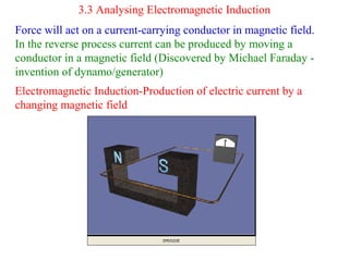
- 1. 3.3 Analysing Electromagnetic Induction Force will act on a current-carrying conductor in magnetic field. In the reverse process current can be produced by moving a conductor in a magnetic field (Discovered by Michael Faraday - invention of dynamo/generator) Electromagnetic Induction-Production of electric current by a changing magnetic field
- 2. Induced current is produced only when there is a relative motion between the conductor/coil and the magnetic field lines. The direction of induced current is influence by the direction of relative motion
- 3. Experiment to observed electromagnetic induction in a straight wire and a solenoid Action Observation Wire-downwards Current flows Wire-upwards Current flows-opposite direction Wire-horizontally No current generated Magnet-upwards Current flows Magnet & wire move together No current generated Wire-stationary No current generated
- 4. Action Observation N-pole into solenoid Current flows Magnet moved out of solenoid Current flows-opposite direction Solenoid into stationary magnet No current generated Magnet held stationary in magnet No current generated Magnet & wire move together In the same direction No current generated
- 5. Induced Current and Induced Electromotive Force When a wire moves and cuts the magnetic field lines, there is a change of magnetic flux, an e.m.f. is induced across the wire Magnetic flux is the number of magnetic lines passing through the surface of a conductor
- 7. The magnitude of the induced e.m.f. can be determined by Faraday’s Law The direction of the induced e.m.f. can be determined by Lenz’s Law and also Fleming’s right-hand rule or right hand slap rule
- 8. Laws of Electromagnetic Induction Faraday’s Law: The magnitude of the induced e.m.f. is directly proportional to the rate of change of magnetic flux or the rate of cutting of the magnetic field lines. For a solenoid, the magnitude of induced e.m.f. can be increased by (a) Increasing the relative speed of motion of wire/solenoid (b) Increasing the number of turns (c) Using a stronger magnet
- 10. For a straight wire, the magnitude of induced e.m.f. can be increased by (a) Increasing the speed of motion of wire (b) Increasing the strength of the magnetic field The magnitude of the induced current depends on (a) The magnitude of the induced e.m.f. (b) The resistance of the circuit
- 11. Lenz’s Law: The induced current always flows in such a direction so as to oppose the change (or motion) producing it.
- 13. Lenz’s Law is a form of the law of conservation of energy Electrical energy cannot be created without any form of work being done. When a magnet moves towards or away from a coil , work must be done to overcome the opposing force The work done (mechanical energy) is converted into electrical energy
- 14. Application of Electromagnetic Induction Dynamic Microphone (Moving coil microphone) Sounds waves vibrates diaphragm which is attracted to a coil. The motion of the coil relative to the magnet induces a current in the coil. The induced current has the same characteristic as the sound wave received.
- 15. Bicycle dynamo It consists of a cylindrical permanent magnet with poles on opposite sides placed within concave poles of a soft iron core where a solenoid is wound It needs no slip rings and commutators and also it doesn’t need carbon brushes
- 16. Direct Current Generator (D.C. Dynamo) Ends of coil are connected to split-ring commutator Two halves of the split-ring exchange contact with the carbon brushes every half rotation Output current flows in one direction through the load resistance, R
- 19. Alternating Current Generator (A.C. Dynamo) Ends of coil are connected to two slip rings Each slip ring is always in contact with the same carbon brush Output current flows to and fro in the opposite direction Increasing the speed of rotation of the coil also increases the frequency of the output voltage.
- 22. Direct Current (D.C.) (1) Current that flows in one direction only in a circuit (2) Magnitude may be (a) constant (b) changes with time (3) Current-time graph
- 24. (4) Current cannot flow through a capacitor (5) No effect on moving coil loudspeaker
- 25. Alternating Current (A.C.) (1) Current which flows to and fro in two opposite directions in a Circuit. It changes its direction periodically (2) Magnitude may be (a) constant (b) changes with time (3) Current-time graph A.C. with constant magnitude A.C. with varying magnitude
- 27. (4) Current can flow through a capacitor (5) Vibrating effect on moving coil loudspeaker
- 28. Comparison between d.c. and a.c. d.c. a.c. Currents flows in 1 direction Current flows to and fro in opposite direction Produces fixed magnetic poles when it passes though a solenoid Produces changing magnetic poles when it passes though a solenoid Cannot pass through a capacitor Can pass through a capacitor Cannot produce vibrating effect on moving coil loudspeaker Can produce vibrating effect on moving coil loudspeaker Magnitude cannot be step up of step down by using transformer Magnitude can be step up of step down by using transformer Can be measured by moving- coil meters, hot-wire meters or moving iron meters Can be measure by hot wire and moving –iron meters only Difficult to be converted to a.c. Can be easily converted to d.c. using rectifiers
- 29. Peak Value and Root-Mean-Square Value The root-mean-square-current Ir.m.s. of an a.c. is the effective value of that a.c. current Definition: Ir.m.s. Is the same as the steady direct current which passing through the same resistor, produces heat at the same rate as that of the a.c. current
- 30. (1) Initially switch is closed on the a.c. circuit and the brightness of the bulb is measured using light intensity meter . The display on CRO is observed and the peak voltage Vo is noted. (2) After that switch is push to the d.c. circuit. Rheostat is adjusted until the bulb gives the same brightness as before. The display on the CRO and the value of d.c. is noted. (3) The above activities is repeated using 2.5 V bulb Bulb V0 Vd.c. Vd.c.. / V0 Bulb 1 ( 3.8 V ) 4.0 2.8 0.7 Bulb 2 ( 2.5 V ) 3.0 2.1 0.7
- 31. Vd.c.. = 0.7 Vo Therefore Vr.m.s. = 0.7 Vo = Vo / √2 For a.c. source, Voltage Vr.m.s. = Vo / √2 For a.c. source, Current Ir.m.s. = Io /√2 Example:- The Voltage supply to our house is 240V. What is the maximum voltage of the power supply. Answer:- Using V r.m.s = Vo / √2 VO = √2 x 240 =339V
- 32. Example: The graph shows the output current of an alternating current Generator. Which statement is true about the graph? A.The peak current is 8A B. The root mean square current is 2 A C. The time for one cycle is 0.4 S D. The frequency of the current generated is 25 Hz Solution:- Io =4A, Ir.m.s. Io/ √2 = 2.8 A, T =0.4 s f=1/T =2.5 Hz Answer: C
- 33. Example: State two (a) similarities (b) differences Between a d.c. generator and an a.c. generator Answer:- (a) (i) Produces an e.m.f. using electromagnetic induction (ii) The output current flows out through carbon brushes (b). D.C. generator A.C. generator Ends of coil connected to split- ring commutator Ends of coil connected to two slip rings Output is a direct current Output is a alternating current
- 34. Example: The induced currents flow in the directions as shown in the diagrams below. Determine (a) The poles at P and Q (b) The pole at X. Answer: (a) P=south Q=north (b) X=south
- 35. Example: A bar magnet is placed between two coils as shown in the following diagram When the bar magnet is withdrawn, what are the poles at P and Q ? In what direction will the induced current flow along wire AB? Give an explanation. Answer: P is south pole and Q is north pole. Because the number of turns in the solenoid QW is more than the number of turns in the solenoid VP, the induced e.m.f. in QW is greater than the induced e.m.f. in VP. The resultant current flows from A to B
- 36. Meters to measure d.c and a.c.
- 37. Example of converting a milliammeter into ammeter A multiplier is connected in parallel to a milliammeter to adapt it as an ammeter. Consider the milliammeter which has a resistance of 5Ω and a full-scale deflection current of 10 mA. Calculate the shunt resistance required for the meter to be adapted to measure up to 5.0A Solution: p.d. across milliammeter= p.d. across the shunt 10 x 10-3 (5) = (5-0.01)Rs Rs =0.01 x 5/4.99 =0.01Ω
- 38. Example of converting a milliammeter into a voltmeter A multiplier is connected in series to a with a milliammeter to adapt it as a voltmeter measure up to 5V. If the coil resistance of the milliammeter is 5 Ω and the full scale deflection current is 10 mA, determine the resistance of the multiplier Solution: When a p.d. of 5 V is applied across the multiplier and the meter, current of 10 mA(0.01 A) flows 5= 0.01(R+5) R+5 =5/0.01 =500 R =495 Ω