1. CIRCUIT
IDEAS
DIGITAL DICE S.C. DW
IVEDI
SAGAR G. YADAV The circuit is divided into three sec- LED2 and LED5 always glow at the
tions: counter, logic and display. same count, as do LED1 and LED6,
T
he digital dice presented here The counter section is built around and LED3 and LED4. Using these three
acts just like a normal dice. It binary counter IC CD4060BC (IC1). pairs of LEDs and LED7, four logical
has six faces (refer Fig. 2) like The counter frequency (f) is decided combinations have been made in the
the normal dice and uses four differ- by the in-built oscillator formed by re- circuit. LED1 and LED6 glow at all
ent logic gate combinations to bring sistor R1 and capacitor C1 as follows: counts, except ‘0’ and ‘1.’ Further, it
out the six faces of the dice. f=1/2.2R1C1. can be noticed that they glow when
At the heart of the circuit is a 14- Here, the frequency is fixed at around ‘A’ or ‘B’ is high, hence a NOR gate
stage ripple-carry binary counter IC 2056 Hz. whose output is A+B according to
CD4060BC (IC1) with built-in oscilla- Only the first three outputs of the Boolean algebra will perform the job
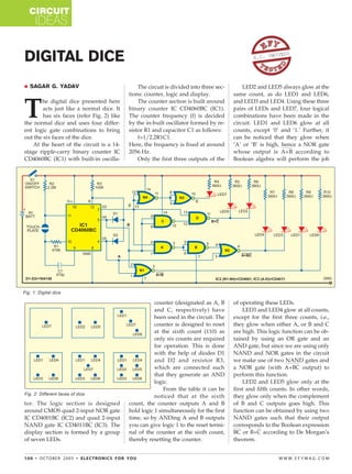
Fig. 1: Digital dice
counter (designated as A, B of operating these LEDs.
and C, respectively) have LED3 and LED4 glow at all counts,
been used in the circuit. The except for the first three counts, i.e.,
counter is designed to reset they glow when either A, or B and C
at the sixth count (110) as are high. This logic function can be ob-
only six counts are required tained by using an OR gate and an
for operation. This is done AND gate, but since we are using only
with the help of diodes D1 NAND and NOR gates in the circuit
and D2 and resistor R3, we make use of two NAND gates and
which are connected such a NOR gate (with A+BC output) to
that they generate an AND perform this function.
logic. LED2 and LED5 glow only at the
From the table it can be first and fifth counts. In other words,
Fig. 2: Different faces of dice
noticed that at the sixth they glow only when the complement
tor. The logic section is designed count, the counter outputs A and B of B and C outputs goes high. This
around CMOS quad 2-input NOR gate hold logic 1 simultaneously for the first function can be obtained by using two
IC CD4001BC (IC2) and quad 2-input time, so by ANDing A and B outputs NAND gates such that their output
NAND gate IC CD4011BC (IC3). The you can give logic 1 to the reset termi- corresponds to the Boolean expression
display section is formed by a group nal of the counter at the sixth count, BC or B+C according to De Morgan’s
of seven LEDs. thereby resetting the counter. theorem.
100 • OCTOBER 2005 • ELECTRONICS FOR YOU WWW.EFYMAG.COM
CMYK
2. CIRCUIT
IDEAS
LEDs of the display section
Dice Score and LEDs Lit at Different Counts will appear to glow simultaneously
Count Dice A B C LEDs lit due to the high counter frequency.
score
This high-frequency counting will
0 1 0 0 0 — — — LE D7 make the dice foolproof. When you
1 2 0 0 1 — — LED2 — LED5
2 3 0 1 0 LED1 — — LED7 — — LED6 remove your finger from the touch
3 4 0 1 1 LED1 LED3 — — — LED4 LED6 pad, the counter will stop counting
4 5 1 0 0 LED1 LED3 — LED7 — LED4 LED6 and the display section will show any
5 6 1 0 1 LED1 LED3 LED2 — LED5 LED4 LED6 one of the six possible faces with a
6 — 1 1 0 — — — — — — —
probability of 1/6.
The entire circuit can be powered
LED7 glows at even counts like 0, common cathodes, as do LED2 and by a 9V battery as the inbuilt oscilla-
2 and 4. In other words, it glows LED5, and LED3 and LED4. The an- tor of the counter IC will not work
when the C output is low. This func- odes of all the LEDs are tied together properly below 7V. Use of CMOS ICs
tion can be achieved easily by invert- to the positive terminal of the battery means less power consumption.
ing the C output twice using the re- via resistors R4 through R10, respec- The circuit can be constructed on a
maining two NAND gates. The out- tively. general-purpose PCB and housed in-
put will also be buffered by these two When you place your finger on side a plastic case with the LEDs array
inverter gates. the touch pad, the oscillator starts os- mounted on the top as shown in Fig.
The display section comprises cillating. The counter will start count- 2. The touch pad can be mounted be-
seven LEDs. LED1 and LED6 have ing at the rate of 2056 Hz and all the side the array.
WWW.EFYMAG.COM ELECTRONICS FOR YOU • OCTOBER 2005 • 101
CMYK