Alarm system wireless to wired adaptor
•
0 gefällt mir•27 views

Different brands wireless alarm device can not work together because they use different wireless communication protocol. How to connect them? The wireless to wired adaptor is the component to connect them. https://vedard.com/blog/linkage-of-burglar-alarm-and-video-surveillance-system/

Empfohlen
Weitere ähnliche Inhalte
Was ist angesagt?
Was ist angesagt? (20)
Ähnlich wie Alarm system wireless to wired adaptor
Ähnlich wie Alarm system wireless to wired adaptor (20)
Mehr von Vedard Security Alarm System Store
Mehr von Vedard Security Alarm System Store (20)
Kürzlich hochgeladen
Kürzlich hochgeladen (20)
Alarm system wireless to wired adaptor
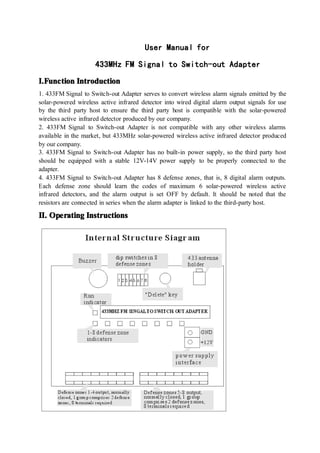
- 1. User User User User Manual Manual Manual Manual for for for for 433MHz 433MHz 433MHz 433MHz FM FM FM FM S S S Signal ignal ignal ignal to to to to Switch-out Switch-out Switch-out Switch-out Adapter Adapter Adapter Adapter I. I. I. I.Function Function Function Function Introduction Introduction Introduction Introduction 1. 433FM Signal to Switch-out Adapter serves to convert wireless alarm signals emitted by the solar-powered wireless active infrared detector into wired digital alarm output signals for use by the third party host to ensure the third party host is compatible with the solar-powered wireless active infrared detector produced by our company. 2. 433FM Signal to Switch-out Adapter is not compatible with any other wireless alarms available in the market, but 433MHz solar-powered wireless active infrared detector produced by our company. 3. 433FM Signal to Switch-out Adapter has no built-in power supply, so the third party host should be equipped with a stable 12V-14V power supply to be properly connected to the adapter. 4. 433FM Signal to Switch-out Adapter has 8 defense zones, that is, 8 digital alarm outputs. Each defense zone should learn the codes of maximum 6 solar-powered wireless active infrared detectors, and the alarm output is set OFF by default. It should be noted that the resistors are connected in series when the alarm adapter is linked to the third-party host. II. II. II. II. Operating Operating Operating Operating Instructions Instructions Instructions Instructions
- 2. 1 1 1 1、Operation Operation Operation Operation Phenomena Phenomena Phenomena Phenomena � In Run mode, the “Run” indicator of the adapter flashes about every 1 second. � In Run mode, 8-digit dip switches of the adapter are all in OFF position, and the alarm, low voltage or light disturbance signal transmitted by the detector is valid. � When the detector transmits an alarm signal, the indicator of the corresponding zone will be on continuously, and the zone’s output will be changed from normally closed to opened. Once the detector resumes its normal operation, the indicator will go out in 30 seconds, and the output will be normally closed. If the detector fails to resume its normal operation, the indicator of the corresponding defense zone will be turned on and the relay output will be opened. � If the detector fails to work (low voltage, power failure, light disturbance and other failures), the relay doesn’t work, and only the indicator lamp in the corresponding defense zone flashes. � The alarm signal prioritizes the error signal, that is, when the alarm signal and error signal are given out simultaneously in a defense zone, the alarm information will be displayed first in this defense zone, and then the error information will be displayed. 2 2 2 2、 Code Code Code Code Learning Learning Learning Learning � When the dip switch in any defense zone is set at ON position, the adapter begins to learn codes with detectors, and at the same time, the indicator lamp of the corresponding defense zone is on continuously and the Run indicator will not be turned on. At this time, no alarm can be triggered, and alarm signal is regarded as signal for learning and memorized by the adapter. Once alarm signal is memorized, the operation lamp flashes fast several times. Alarm signal from the same detector or the same defense zone can not be memorized repeatedly, but alarm signals from multiple defense zones can be learnt over again. It shall be noted that only alarm signal can be learnt. � Once the adapter has learnt codes with 6 detectors in any defense zone, the buzzer will buzz several times to indicate that learning has been completed. � Please avoid falsely triggering any detector not available so as to prevent unnecessary signals from interfering with code learning. � Only one defense zone is allowed to learn codes with detectors at a time, and multiple defense zones are not allowed to learn codes with detectors at a time. When more than one keys in an 8-digit dip switch are ON position, that is, indicators in more than 1 defense zones are on during setting, the adapter buzzer will buzz continuously. At this time, the adapter does not work normally. 3 3 3 3、 Delete Delete Delete Delete Defense Defense Defense Defense Zone Zone Zone Zone � The defense zone shall be deleted in Learn mode. When all keys of the dip switch of the defense zone to be deleted are set at ON position, the indicator lamp of the corresponding defense zone lights up. At this time, press and hold down DELETE key for about 2 seconds until the indicator lamp flashes. At this time, all information about detectors learnt by the adapter in this defense zone will be deleted. � Never avoid triggering an alarm during deletion and thus causing repeatedly learning.
- 3. III.Connection III.Connection III.Connection III.Connection Instructions Instructions Instructions Instructions Please Please Please Please follow follow follow follow the the the the steps steps steps steps below below below below to to to to install install install install the the the the adapter: adapter: adapter: adapter: 1. Please properly connect the adapter with the host as shown in the Figure (see Figure above), and insert the antenna into the interface at the upper left of the adapter. It should be specially noted that the positive and negative polarity of power supply should be correctly connected, and all other wires should lead out through holes opened at the lower of junction box of the adapter. 2. Power on 2 devices and observe if indicator lamps operate normally. If any failure occurs, please cut off power supply immediately and check if lines are properly connected to avoid device burn-out. 3. Before operation, please delete 8 defense zones of the adapter as per this User Manual to avoid any invalid alarm from invalid detectors. 4. Let the relevant defense zones enter into code learning mode, trigger a detector one time; if the operation lamp flashes several times, this detector has been memorized. It is possible to trigger a detector several times to ensure this detector is really memorized. Never trigger other detectors to avoid false learning. If the adapter has successfully learnt alarm signal of a detector, let the adapter learn alarm signal of the next detector. The adapter can learn codes of maximum 6 detectors in a defense zone until it completes learning alarm signals of detectors in all other defense zones. 5. Once the adapter has completed learning, please keep the adapter under operating state (Ensure 8-digit dip switches in all defense zones are set to OFF position). Please let all detectors learnt by the adapter attempt to trigger an alarm several times to verify if the adapter correctly outputs relevant alarm signals. If any failure occurs, please delete relevant defense zones, let the adapter learn detectors again and try to let the adapter trigger the alarm once.
- 4. 6. If no failure is found, please cover up the back panel and place the adapter in a proper place. I I I IV V V V.Technical .Technical .Technical .Technical Specifications Specifications Specifications Specifications Operating Voltage: 12V-14V Operating Current: 100mA~150mA Operating Conditions: -30℃-70℃ (This product is not waterproof, so it shall not be placed in an open area.) Wireless Distance: 100-300m(depending on power supply and operating conditions) Storage Capacity: 8x6 structure, 8 defense zones, 8 digital outputs; the adapter can learn codes with 6 detectors in each defense zone.