Manual de Recarga Samsung CLP 500 CLP 550
•
1 gefällt mir•1,072 views

Manual utilizado nos modelos Samsung para Impressoras CLP 500 | CLP 550.

Empfohlen
Weitere ähnliche Inhalte
Was ist angesagt?
Andere mochten auch
Andere mochten auch (15)
Ähnlich wie Manual de Recarga Samsung CLP 500 CLP 550
Ähnlich wie Manual de Recarga Samsung CLP 500 CLP 550 (19)
Mehr von Valejet
Mehr von Valejet (16)
Manual de Recarga Samsung CLP 500 CLP 550
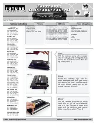
- 1. CLP500_550_510TECH Technical Instructions Printers OEM Info Tools & Supplies 1 CORPORATE CLP-500, 500N CLP-500D5C Cyan Toner Yield @ 5%: 5,000pgs Tools: CLP-500D5M Magenta Toner Yield @ 5%: 5,000pgs LOS ANGELES, USA CLP-550, 550N CLP-500D5Y Yellow Toner Yield @ 5%: 5,000pgs Needlenose Pliers US 1 800 394.9900 CLP-510, 510N CLP-500D7K Black Toner Yield @ 5%: 7,000pgs #2 Phillips head screw driver Int’l +1 818 837.8100 CLP-511, 515, 560, 560N CLP-510D5C Cyan Toner Yield @ 5%: 5,000pgs Small flat blade screw driver FAX 1 800 394.9910 CLP-510D5M Magenta Toner Yield @ 5%: 5,000pgs CLP-510D5Y Yellow Toner Yield @ 5%: 5,000pgs Int’l +1 818 838.7047 CLP-510D7K Black Toner Yield @ 5%: 7,000pgs Supplies: CLP-510D2C Cyan Toner Yield @ 5%: 2,000pgs Toner ATLANTA, USA CLP-510D2M Magenta Toner Yield @ 5%: 2,000pgs US 1 877 676.4223 CLP-510D2Y Yellow Toner Yield @ 5%: 2,000pgs Swabs Int’l +1 770 516.9488 CLP-510D2K Black Toner Yield @ 5%: 3,000pgs Lint Free Cloth FAX 1 877 337.7976 Int’l +1 770 516.7794 DALLAS, USA US 1 877 499.4989 Int’l +1 972 840.4989 FAX 1 877 774.1750 Int’l +1 972 840.1750 MIAMI, USA Photo 1 US 1 800 595.429 Step 1 Int’l +1 305 594.3396 FAX 1 800 522.8640 With the cartridge facing with developer Int’l +1 305 594.3309 roller towards you and cartridge label up, NEW YORK, USA remove the four Phillip screws from the US 1 800 431.7884 Int’l +1 631 345.0121 top cover. (Photo 1) FAX 1 800 431.8812 Int’l +1 631345.0690 SANFORD,USA US 1 800 786.9049 Int’l +1 919 775.4584 FAX 1 800 786.9049 Int’l +1 919 775.4584 TORONTO, CAN Photo 2 CAN 1 877 848.0818 Step 2 Int’l +1 905 712.9501 Rotate the cartridge right with the FAX 1 877 772.6773 Int’l +1 905 712.9502 larger developer roller drive gear facing BUENOS AIRES, ARG you. Remove the Phillip screw located in ARG 0810 444.2656 the right bottom. Gently pry up and Int’l +011 4583.5900 remove the cover. (Photo 2) FAX +011 4584.3100 MELBOURNE, AUS AUS 1 800 003. 100 Int’l +62 03 9561.8102 FAX 1 800 004.302 Int’l +62 03 9561-7751 SYDNEY, AUS Photo 3 AUS 1 800 003.100 Step 3 Int’l +62 02 9648.2630 FAX 1800 004.302 Turn the cartridge so the fill cap end is Int’l +62 02 9548.2635 facing you. Pry off the black developer MONTEVIDEO,URY gear end cap. Remove all three white URY 02 902.7206 gears and the developer gear spacer, Int’l +5982 900.8358 FAX +5982 908.3816 taking note of orientation. (Photo 3) JOHANNESBURG, S.A. S.A. +27 11 974.6155 FAX +27 11 974.3593 E-mail: info@futuregraphicsllc.com Website: www.futuregraphicsllc.com
- 2. 2 Samsung CLP500/550/510 Technical Instructions Photo 4 Step 4 Remove the “e” clip from the developer roller shaft and the bushing insert. Notes (Photo 4) Photo 5 Step 5 Optional Rotate the cartridge to the opposite side with the developer bias circuit board fac- ing you. Remove the three Phillip screws on the circuit board and remove both the contact and board. (Photo 5) Photo 6 Step 6 Optional Remove the two Phillip screws that hold the gear train plate in place. The gears are now easily removed. Only the gear on the developer roller needs to be removed in order to remove the developer roller drive gear. (Photo 6) NOTE: Mark gear order for easy reassemble. Photo 7 Step 7 Pry off the black developer roller gear end cap. Remove the small flat washer, white developer roller drive gear and developer gear spacer. (Photo 7) Step 8 Photo 8 Rotate the cartridge so that the developer roller is facing you. Carefully pull the left side of the developer roller shaft outward enough to clear the housing. Once clear, pull the developer roller towards the left and remove (be careful not to scratch the developer roller surface). Note that there are thin Mylar type washers on both sides of the developer roller shaft -- don’t lose them! (Photo 8)
- 3. Samsung CLP500/550/510 Technical Instructions Photo 9 Step 9 Rotate the cartridge so that the fill plug is facing you and remove. Clean out any remaining toner from the reservoir. Notes (Photo 9) Photo 10 Step 10 Taking the cleaned developer roller install it back into the cartridge with the longer shaft towards the gear set keeping it level. Take care that the thin Mylar washers set properly and do not get damaged. (Photo 10) Photo 11 Step 11 Turn the cartridge so that the gear train side is facing you. Reinstall the developer roller gear spacer, white developer roller drive gear and washer. Press on the black developer roller gear end cap. (Photo 11) Photo 12 Step 12 Replace the one white gear that was removed from the gear train, the gear train plate, developer bias circuit board and contact. The gear train plate requires two Phillip screws and the developer bias board and contact require three. (Photo 12) Photo 13 Step 13 Rotate the cartridge to the opposite end and reinstall the bushing, “e” clip, devel- oper roller gear spacer and the three white gears. Press on the black developer gear end cap. (Photo 13)
- 4. 4 Samsung CLP500/550/510 Technical Instructions Photo 14 Step 14 Fill the cartridge with toner and replace the fill cap. (Photo 14) Photo 16 Photo 15 Step 15 Replace the cover back onto the cartridge and reinstall the five Phillip screws. (Photo 15 & 16) The Samsung CLP-500, CLP-500N, CLP-550 and CLP-550N are color laser printers designed for businesses in the small to medium size range. The printers offer up to 5ppm color and 21ppm black and white with print resolution up to 1200 dpi. The printers include automatic built in duplexing, Hi-Speed USB connectivity and have options such as 500 sheet paper handling and network connectivity. Supplies for the printers come with starter toners, black at 2,000 pages and 1,500 for the color. Included are the waste toner container (3,000 pages), Imaging unit (50K/12K pages Black/Color) and the transfer belt (50K/12K pages Black/Color). Replacement toner cartridges are rated at black 7,000 pages and color 5,000 pages with the asterisk “usage conditions and print patterns may cause results to vary”. Future Graphics (FG) is a distributor of compatible replacement parts and products for imagining equipment. None of FG's products are genuine OEM replacement parts and no affiliation or sponsorship is to be implied between FG and any OEM. E-mail: info@futuregraphicsllc.com Website: www.futuregraphicsllc.com
- 5. CLP-500 Cartridge Reset System Installation Instructions CLP500RESET Photo 2 Attention: The following procedure requires Step 2 experience in soldering electronic components. Hold the Cartridge Contacts Assembly in a vise or similar clamping device. Tool Requirements: Small Blade Screw Driver (See Photo 2) Needle Nose Pliers Small Vise Soldering Iron – 600°F to 800°F temperature range, Conical tip recommended. Silver Solder Photo 3 PIN 3 Photo 1 PIN 1 Step 3 Remove the component soldered to the two outside contact tabs (pins 1 and 3). Step 1 Holding the wire with needlenose pliers on one side of the contact tab, apply the heated solder iron onto the other side of the tab. As Using a small blade screw driver, carefully remove the solder melts, gently pull the wire with the needle nose pliers. the Cartridge Contacts Assembly from the side of Warning: DO NOT OVER HEAT the tab because the plastic the cartridge. housing is very easily melted. (See Photo 1) Repeat above instructions on the other outside contact tab. (See Photo 3) w w w. f u t u re g r a p h i c s l l c . c o m 1 REV. 10/02/05 CLPCRSTECH_ver.2
- 6. CLP-500 Cartridge Reset System Installation Instructions Photo 4 Photo 7 Step 4 Use solder iron to smooth and minimize the remain- ing solder on the contact tabs. Step 7 Warning: DO NOT OVER HEAT the tab because (Optional) Solder connectors to the contact tabs. the plastic housing is very easily melted. Warning: DO NOT OVER HEAT the tab because (See Photo 4) the plastic housing is very easily melted. (See Photo 6) Photo 5 Photo 8 Step 5 Check tightness of connectors on the tabs. If loose, remove assembly from the tabs. Use needlenose pliers to tighten connector gap and reinstall onto the tabs. (See Photo 5) Step 8 Reinstall Cartridge Contacts Assembly onto the car- Photo 6 tridge. (See Photo 8) Need trustworthy, detailed Technical Instructions for another engine? V i s i t : w w w. f u t u re g r a p h i c s l l c . c o m Step 6 Install Cartridge Reset System onto the two out- side contact tabs. (See Photo 6) Future Graphics (FG) is a distributor of compatible replacement parts and products for imagining equipment. None of FG's products are genuine OEM replacement parts and no affiliation or sponsorship is to be implied between FG and any OEM. w w w. f u t u re g r a p h i c s l l c . c o m 2 CLPCRSTECH_ver.2
- 7. CLP-510 Chip Replacement Procedure Installation Instructions CLP-510 Chip Board Photo 2 Part Numbers: CLP510CHIPK CLP510CHIPC CLP510CHIPM CLP510CHIPY Attention: The following procedure requires experience in soldering electronic components. Step 2 Hold the Cartridge Contacts Assembly in a vise or Tool Requirements: similar clamping device. Small Blade Screw Driver Needle Nose Pliers (See Photo 2) Small Vise Soldering Iron – 600°F to 800°F temperature range, Conical tip recommended. Silver Solder Solder-Wick Photo 3 CONTACT TAB 3 Photo 1 CONTACT TAB 1 Step 3 Using the solder removal device and soldering iron, remove all solder holding the Chip Board to the con- tact tabs. Using a needle nose pliers, gently pull the Chip Board from the contact tabs. Step 1 (See Photo 3) Using a small blade screw driver, carefully remove If the Chip Board is still attached to the contact tabs, the Cartridge Contacts Assembly from the side of reheating the contact tab with soldering iron and the cartridge. gently pull with the needle nose pliers. (See Photo 4) (See Photo 1) Warning: DO NOT OVER HEAT the tab because the plastic housing is very easily melted. w w w. f u t u re g r a p h i c s l l c . c o m 1 REV. 10/31/05 CLP510CHIPTECH
- 8. CLP-510 Chip Replacement Procedure Installation Instructions Photo 4 Photo 6 Photo 5 Step 5 Reinstall Cartridge Contacts Assembly onto the cartridge. (See Photo 6) Step 4 Position CLP-510 Chip Board notched area closest to the contacts. Solder contact tabs to the Chip Board. (See Photo 5) Warning: DO NOT OVER HEAT the tab because the plastic housing is very easily melted. Need trustworthy, detailed Technical Instructions for another engine? V i s i t : w w w. f u t u re g r a p h i c s l l c . c o m Future Graphics (FG) is a distributor of compatible replacement parts and products for imagining equipment. None of FG's products are genuine OEM replacement parts and no affiliation or sponsorship is to be implied between FG and any OEM. w w w. f u t u re g r a p h i c s l l c . c o m 2 REV. 10/31/05 CLP510CHIPTECH