SlideShare ist ein Scribd-Unternehmen logo
1 von 18
Downloaden Sie, um offline zu lesen
ABC of PON: Understanding OLT, ONU, ONT and ODN
In recent years, Fiber to the Home (FTTH) has started to be taken seriously by telecommunication
companies around the world, and enabling technologies are being developed rapidly. There are two
important types of systems that make FTTH broadband connections possible. These are active optical
networks (AON) and passive optical networks (PON). By far the majority of FTTH deployments in
planning and in deployment use a PON in order to save on fiber costs. PON has recently attracted
much attention due to its low cost and high performance. In this post, we are going to introduce the
ABC of PON which mainly involves the basic components and related technology, including OLT,
ONT, ONU and ODN.
First of all, it is necessary to have a brief introduction of PON. In contrast to AON, multiple customers
are connected to a single transceiver by means of a branching tree of fibers and passive
splitter/combiner units, operating entirely in the optical domain and without power in PON. There are
two major current PON standards: Gigabit Passive Optical Network (GPON) and Ethernet Passive
Optical Network (EPON). But no matter which type of PONs, they have a same basic topology
structure. A Gigabit Ethernet Passive Optical Network (GEPON) system is generally composed of an
optical line terminal (OLT) at the service provider's central office and a number of optical network units
(ONUs) or optical network terminals (ONTs) near end users, as well as the optical splitter. In addition,
the optical distribution network (ODN) is used during the transmission between OLT and ONU/ONT.
Optical Line Terminal (OLT)
OLT a equipment integrating L2/L3 switch function in GEPON system. In general, OLT equipment
contains rack, CSM (Control and Switch Module), ELM (EPON Link Module, PON card), redundancy
protection -48V DC power supply modules or one 110/220V AC power supply module, and fans. In
these parts, PON card and power supply support hot swap while other module is built inside. The main
function of OLT is to control the information float across the ODN, going both directions, while being
located in a central office. Maximum distance supported for transmitting across the ODN is 20 km.
OLT has two float directions: upstream (getting an distributing different type of data and voice traffic
from users) and downstream (getting data, voice and video traffic from metro network or from a long-
haul network and send it to all ONT modules on the ODN.
Optical Network Unit (ONU)
ONU converts optical signals transmitted via fiber to electrical signals. These electrical signals are
then sent to individual subscribers. In general, there is a distance or other access network between
ONU and end user's premises. Furthermore, ONU can send, aggregate and groom different types of
data coming from the customer and send it upstream to the OLT. Grooming is the process that
optimises and reorganises the data stream so it would be delivered more efficiently. OLT supports
bandwidth allocation that allows making smooth delivery of data float to the OLT, that usually arrives
in bursts from the customer. ONU could be connected by various methods and cable types, like
twisted-pair copper wire, coaxial cable, optical fiber or Wi-Fi.
Optical Network Terminal (ONT)
Actually, ONT is the same as ONU in essence. ONT is an ITU-T term, whereas ONU is an IEEE term.
They both refer to the user side equipment in GEPON system. But in practice, there is a little difference
between ONT and ONU according to their location. ONT is generally on customer premises.
Optical Distribution Network (ODN)
ODN, an integral part of the PON system, provides the optical transmission medium for the physical
connection of the ONUs to the OLTs. Its reach is 20 km or farther. Within the ODN, fiber optic cables,
fiber optic connectors, passive optical splitters, and auxiliary components collaborate with each other.
The ODN specifically has five segments which are feeder fiber, optical distribution point, distribution
fiber, optical access point, and drop fiber. The feeder fiber starts from the optical distribution
frame (ODF) in the central office (CO) telecommunications room and ends at the optical distribution
point for long-distance coverage. The distribution fiber from the optical distribution point to the optical
access point distributes optical fibers for areas alongside it. The drop fiber connects the optical access
point to terminals (ONTs), achieving optical fiber drop into user homes. In addition, the ODN is the
very path essential to PON data transmission and its quality directly affects the performance, reliability,
and scalability of the PON system.
Conclusion
There are different types of OLT, ONU, ONT equipment for GEPON, which are the new generation
PON equipments and mainly applied by telecommunication operators in FTTH project. All these
equipment are provided in fiberstore and have the characteristic of high integration, flexible adaption,
reliability and capable of providing QOS, web-management as well as flexible enlarging capacity. For
more information, please contact us over sales@fs.com.
Related Article: AON vs PON Networks: Which One to Choose for FTTH Systems
Related Article: Basic Knowledge About GPON SFP Transceivers
Related Article: How to Design Your FTTH Network Splitting Level and Ratio?
Basic Knowledge About GPON SFP Transceivers
Posted on January 17, 2018 By FS.COM
GPON stands for Gigabit Passive Optical Network. GPON is one of the key technologies that are
being used in fiber-based (FTTx) access networks, including fiber to the home (FTTH), fiber to the
business (FTTB), fiber to the curb (FTTC), etc. GPON system contains two main active transmission
components, namely optical line termination (OLT) and optical network termination (ONT) or optical
network unit (ONU). Modern OLT and ONT/ONU use compact fiber optic modules to achieve the triple-
play GPON services. These modules are known as GPON SFP transceivers. This post will give a
comprehensive introduction to GPON SFP modules.
What Is GPON SFP?
GPON SFP is one type of gigabit optical transceivers that are used in GPON system, which is
compliant with ITU-T G.984.2 standard. It is a bidirectional module that has SC receptacle and works
over simplex single-mode fiber optic cable. A GPON SFP module transmits and receives signals of
different wavelengths between the OLT at the Central Office side and the ONT at the end users side.
GPON SFPs utilize both the upstream data and downstream data by means of Optical Wavelength
Division Multiplexing (WDM).
GPON SFP: Class B+ vs. Class C+
GPON SFP transceivers are categorized into GPON OLT SFP and GPON ONT SFP or GPON ONU
SFP depending on the devices they are used in. And there are Class B+ GPON SFP and Class C+
GPON SFP. The major differences between them are the transmit power and the receive sensitivity.
The table below lists the Tx power and Rx sensitivity of Class B+ GPON SFP and Class C+ GPON
SFP.
Transceiver Type
Class B+ Class C+
Tx power
Max. Rx
sensitivity
Tx power Max. Rx sensitivity
GPON OLT SFP 1.5-5 dBm -28 dBm 3-7 dBm -32 dBm
OLT SFP Operation
Wavelength
1480-1500
nm
1260-1360 nm 1480-1500 nm 1290-1330 nm
GPON ONT SFP 0.5-5 dBm -27 dBm 0.5-5 dBm -30 dBm
ONT SFP Operation
Wavelength
1260-1360
nm
1480-1500 nm 1290-1330 nm 1480-1500 nm
By using Class B+ or Class C+ GPON OLT SFP, it can support up to 32 or 64 ONTs at customer
premises respectively. And a C+ OLT SFP can be used with B+ ONT SFP as long as the loss budget
of the link is appropriate.
Figure 1: GPON SFP Class B+ and Class C+.
How’s the GPON SFP Different From Conventional BiDi SFP?
Although GPON SFP belongs to the gigabit BiDi SFP family, it differs from “normal” BiDi SFPs in some
aspects. Here’s a comparison between GPON SFP transceiver and conventional BiDi SFP
transceiver.
Signal Transmission Mode
In terms of conventional gigabit BiDi SFP transceivers that are mainly used in backbone network, the
optical transmission mode is point to point (P2P), i.e., they must be used in matched pair. A BiDi
usually has LC receptacle instead of SC receptacle. Here’s an illustration of P2P transmission mode.
Figure 2: Transmission mode of conventional SFP.
The transmission mode of GPON SFP is point to multi-point (P2MP). One GPON OLT SFP at the
Central Office communicates with multiple GPON ONT SFPs with the help of fiber optic splitters. This
is why we usually see a GPON infrastructure is in a tree shape or a tee shape.
Figure 3: Transmission mode of GPON SFP.
Transmission Distance
The transmission distance of conventional gigabit BiDi SFP can be up to 160 km over single-mode
fiber cable when using 1590nm/1510nm and 1510nm/1590nm wavelengths. GPON OLT and ONT/
ONU SFP transceivers support a transmission distance up to 20 km with 1490nm/1310nm and
1310nm/1490nm wavelengths.
Benefits of Using GPON SFP
Using GPON SFP is considered a more convenient and cost-effective solution for the end customers.
And it also reduces the devices that need to be provided by the Internet service provider (ISP). Before
the GPON ONT SFP was released and used in GPON networks, the ISP usually needs to install at
least an optical modem (a type of ONT with a fiber optic port) and an IP access router, and a Set-Top-
Box or video recorder might also be needed if IPTV services are required. The separation of different
devices inevitably increased the cost for GPON services.
Figure 4: Optical modem with a fiber optic port.
The newly used GPON SFP is in smaller size and integrates the triple-play services. It has lower
consumption as well. The ISP provides a GPON ONT SFP to the customer. This module is usually
installed in the hub/router handed to the customer by the ISP. The customer is also able to unplug the
fiber optic patch cable and the GPON ONT SFP from the ISP’s hub/router, and then plug them in his
own router/switch that is white-listed by the ISP.
Conclusion
GPON SFP transceivers are typically used in the two main active transmission components OLT and
ONT/ONU in GPON optical networks. They are essential in keeping the high-bandwidth
communication between the service provider and the end users over a distance up to 20 km. GPON
SFPs are classified into Class B+ and Class C+ and the main differences are their Tx power and Rx
sensitivity. This module has simplified the implementation of GPON services. It benefits both the
service providers and the end users to some degree.
Related Article: Understanding Video SFP Transceiver
How to Design Your FTTH Network Splitting Level and Ratio?
Posted on June 1, 2016 By FS.COM
In Passive Optical Network (PON), optical splitters play an important role in Fiber to the Home (FTTH)
networks by allowing a single PON interface to be shared among many subscribers. Optical Splitters
are installed in each optical network between the PON Optical Line Terminal (OLT) and the Optical
Network Terminals (ONTs) that the OLT serves. During the deployment of fiber to the home passive
optical network, usually, we will face some physical access network design problems. This article may
help you solve FTTH splitting level and ratio design problems.
Choose Optical Splitter: PLC Splitter or FBT Splitter?
Before we start to discuss the splitting level and ration design, it’s necessary to choose the right optical
splitter type for your FTTH network. There are two types of optical splitters in our current FTTH
application—PLC splitter and FBT splitter. Here we have a comparison between these two splitter
types:
Parameters PLC Splitter FBT Splitter
Wavelength Range 1260-1650 nm Single/dual/triple window
Splitting Ratio Equal division Equal or non-equal division
Dimensions Small Large size for multi-channel
Wavelength
Sensitivity
Low High
Cost
Low splitting channel, high
price
Price is lower for small channel
spliter
As we can see in the table above, with the rapid growth of FTTH worldwide, the requirement for larger
split configurations (1x32, 1x64, etc) in these networks has also grown in order to serve mass
subscribers, since PLC splitters offer very accurate and even splits with minimal loss in an efficient
package, they are offer a better solution for today’s FTTH applications than FBT splitters.
FTTH Network Splitting Level Design
The PON is the optical fiber infrastructure of an FTTH network. The first crucial architectural decision
for the PON network is that of optical splitter placement. The PON splitting may be achieved by
centralized splitting (one-level) or by cascaded splittings (two-level or more). A centralized approach
typically uses a 1x32 splitter located in a fiber distribution hub (FDH). The splitter is directly connected
via a single fiber to a OLT in the central office. On the other side of the optical splitter, 32 fibers are
routed to 32 customers’ homes, where it is connected to an ONT. Thus, the PON network connects
one OLT port to 32 ONTs.
A cascaded approach may use a 1x4 splitter residing in an outside plant enclosure. This is directly
connected to an OLT port in the central office. Each of the four fibers leaving this lever 1 splitter is
routed to an access terminal that houses a 1x8 level 2 splitter. In this scenario, there would be a also
total of 32 fibers (4x8) reaching 32 homes. It is possible to have more than two splitting levels in a
cascaded system, and the overall split ratio may vary (1x16 = 4x4, 1x32 = 4x8, 1x64 = 4x4x4).
A centralized architecture typically offers greater flexibility, lower operational costs and easier access
for technicians. A cascaded approach may yield a faster return-on-investment with lower first-in and
fiber costs. Usually, the centralized splitting solution is used in crowded city center or town areas, in
order to reduce cost and easy to maintain the optical distributed network (ODN) nodes. In the other
hand, two-level and multi-level cascaded splitting solution is used in curb or village places, to cover
widely ODN nodes, conserve resources and save the money.
FTTH Network Splitting Ratio Design
The most common optical splitters deployed in a PON system is a uniform power splitter with a 1:N or
2:N splitting ratio (N=2~64), where N is the number of output ports. The optical input power is
distributed uniformly across all output ports. Different ratio splitters may perform differently in your
network. Then, how to design your splitting ratio? According to the passage mentioned above, if you
choose the centralized splitting solution, you may need to use 1x32 or 1x64 splitter. However, if you
choose the cascaded splitting solution, 1x4 and 1x8 splitter may be used more often. Besides, based
on our EPON/GPON project experience, when the splitting ratio is 1:32, your current network can
receive qualified fiber optic signal in 20 km. If your distance between OLT and ONU is small, like in 5
km, you can also consider about 1:64.
Conclusion
When to design your FTTH network splitting level, in fact, centralized splitting and cascaded splitting
both has its advantages and disadvantages. We had to weight these factors and select an appropriate
splitting level for our network. As for splitting ratio design, to ensure a reliable signal transmission, the
longer the transmission distance, the lower splitting ratio should be used. FS.COM provides full series
1xN or 2xN PLC and FBT optical splitters which can divide a single/dual optical input(s) into multiple
optical outputs uniformly, and offer superior optical performance, high stability and high reliability to
meet various application requirements. For more information, you can visit our site to know more
details about our PON splitters.
Related Article: What Is a Fiber Optic Splitter?
Installation Requirements and Network Design
Back to Top
Optical Distribution Network (ODN) planning is critical to a successful GPON
implementation. It is essential to have a well-planned network design to ensure CPEs
receive a usable signal, allow for bandwidth capacity and client count on each PON port,
and save on costs. This is done by balancing optical power, distance, attenuation, and
bandwidth capacity. In the example setup below, a UFiber OLT (UF-OLT or UF-OLT-4) is
used as the core of the GPON network, connecting the PON side to the rest of the routing
and switching domain.
Example GPON topology using an ER-8-XG on the uplink side and a PLC splitter on the
PON side.
The SFP+ uplink port(s) are used to connect UFiber GPON network to the rest of the
routing and switching domain. On the uplink side, we use a high capacity router such as
an ER-8-XG, connected to the OLT using 10Gbps SFP+ fiber modules or DAC cables.
NOTE: See the UFiber Modules and Cables product page for more information on UBNT branded SFP/SFP+ mo
On the PON side, we insert a GPON OLT SFP module (UF-GP-B+ / UF-GP-C+) into the
OLT, supporting up to 128 UFiber ONUs per PON port when using PLC splitters. There are
various options available to properly connect the OLT to the UFiber ONUs (UF-Nano / UF-
LOCO / UF-WIFI). There components that typically make up a GPON network are:
 Feeder cable Fiber cable (SC/UPC to SC/APC) connecting the OLT to a distribution point,
typically a PLC splitter.
 PLC Splitter Fiber splitter that distributes the fiber connection using multiple available split
ratios.
 Drop cable Fiber cable (SC/APC to SC/APC) providing the final link by connecting the PLC
splitter to the ONU.
 Adapters or Splices Used to inter-connect the different fiber cables and splitters.
The simplest method of connecting UFiber equipment is to use pre-terminated fiber cables
with connectors which can simply plug into the other accessories. The official UFiber GPON
fiber cable and PLC splitter accessories use SC/UPC and SC/APC connectors which can
be used to quickly and easily set up GPON networks. See the Accessories article for more
information. There are also other options available such as mechanical and fusion splicing.
See the Fiber Connectors and Splicing article for more information.
Using either the official accessories or other available fiber equipment, and assuming the
power level and attenuation is calculated correctly (see the Calculation section below), the
ONU will be connected. The acceptable optical power level range at the ONU is -8 dBm to -
28 dBm.
NOTE: The UF-GP-C+ module is capable of higher transmit power which helps overcome attenuation to ensure
the ONU. See our UFiber FAQ article for more information.
Attenuation and Power Level Calculations
Back to Top
This section focuses on attenuation, which is the most important factor in designing a
GPON network. First, we need to become familiar with sources of attenuation so that we
can use them in designing the network and calculation the optical power level (dBm). For
example, the UF-GP-B+ module starts with an output power of +3 dBm, while supporting a
Rx minimum loss of -8 dBm and a maximum loss of -28 dBm. All of the signals must be within
this range.
NOTE: There will be zero throughput if the Rx signal is outside of the maximum/minimum loss range With GPO
example, where you might see a decrease in throughput if the signal is weak.
Common sources of attenuation are:
 Length Attenuation occurs over the distance of a fiber run per kilometer (Km) and differs in
the downstream (~0.3 dB per Km on 1490 nm) and upstream (~0.5 dB per Km on 1310 nm)
frequencies.
 Splices Each splice in a fiber optic run accounts for ~0.1 dB. This seems minimal at first,
however the count of splices in a single run can add up considerably.
 Connectors Each connector accounts for a ~0.6 dB loss. This starts from the SC connector at
the UF-GP-B+ module and ~0.6 dB is added for each other connector.
 Splitter Splitters are essential in a GPON networks to connect multiple ONUs to a single
PON port. See the Splitters section below for more information on using splitters.
These are general attenuation values and different vendors may lead to different values
depending on the quality of the product. Each source of attenuation will decrease the
starting power level to be within the acceptable range for the ONUs.
ATTENTION: Connecting a UFiber ONU directly to the UF-GP-B+ in the PON port from the OLT will potentially c
and/or the OLT because the power is too high.
The acceptable optical power for the UF-Nano is -8 dBm to -28 dBm. The output from the UF-GP-B+ module is
attenuation to provide an acceptable level at the ONU. This is also a factor in the upstream optics where the o
be too high and cause damage to the UF-GP-B+ module.
Upstream and Downstream Calculation Example
Back to Top
This section focuses on how to calculate the optical power the ONU and OLT will receive.
When laying out your fiber distribution network, the goal is to calculate all attenuation in
each fiber run to ensure that when connecting the ONU on the customer’s premises it will
receive a Rx value of -8 dBm to -28 dBm. It is also important that the received signal from the
ONU is also within the same range at the OLT.
Like highlighted in the section above, the common sources of attenuation are:
 Upstream LengthLoss of ~0.5 dB per Km on 1310 nm.
 Downstream LengthLoss of ~0.3 dB per Km on 1490 nm.
 SplicesLoss of ~0.1 dB per splice.
 ConnectorsLoss of ~0.6 dB per connector.
 SplitterLoss of log10(split:ratio) x 10 = Attenuation in dB for each split.
The table below show the general attenuation loss for common splitter ratios:
Split Formula Loss in dB
1:2 log10 (2) x 10 -3.01dB
1:4 log10 (4) x 10 -6.02dB
1:8 log10 (8) x 10 -9.03dB
1:16 log10 (16) x 10 -12.04dB
1:32 log10 (32) x 10 -15.05dB
1:64 log10 (64) x 10 -18.06dB
Using the below network diagram as a guideline, we can use these attenuation sources to
end up within the acceptable optical power levels.
Power level calculation example using an UF-OLT, a 1:32 PLC splitter and a UF-Nano.
Downstream Calculation:
Source Loss of Optical Power Calculation Loss in dB
Length .3dB x 10Km + .3dB x 6Km -4.8dB
Splices .1dB x 2 splices -.2dB
Connectors .6dB x 4 connectors -2.4dB
Splitter 15.05dB for 1:32 splitter -15.05dB
+3 dBm starting power minus loss -19.45dBm
Upstream Calculation:
Source Loss of Optical Power Calculation Loss in dB
Length .5dB x 10Km + .5dB x 6Km -8dB
Splices .1dB x 2 splices -.2dB
Connectors .6dB x 4 connectors -2.4dB
Splitter 15.05dB for 1:32 splitter -15.05dB
+3 dBm starting power minus loss -22.65dBm
Both the upstream and the downstream signals are within the acceptable range.
ATTENTION: The bandwidth will not increase with a better optical power value. Think of this as either on whe
the range. The UF-Nano has a built in display showing the optical power levels of both Rx and Tx to easily iden
acceptable range.
Planning for Capacity vs Client Quantity
Back to Top
When planning your network it is important to plan for future customers and calculate the
available bandwidth on each PON port compared to the client count. There is often a mix of
many clients with relatively low bandwidth needs of around 50 to 100 Mbps, and a smaller
amount of clients requiring 500 Mbps to 1 Gbps bandwidth.
High bandwidth design example:
For highest capacity of bandwidth, connecting a single ONU to a single PON port could
provide a single client 20km away with the full bandwidth of the PON port. Keep in mind that
each of the eight PON ports on the UF-OLT can provide 2.488 Gbps downstream and 1.244
Gbps upstream. In the rare case that a single ONU is used on a single PON port keep in
mind that the bandwidth will be limited by the 1 Gbps LAN copper port on the ONU.
High capacity design example:
For highest capacity of clients. A PLC splitter with a 1:128 ratio connected to a PON port
could provide 128 clients with equal bandwidth of about 19 Mbps download and 9 Mbps
upload when the clients are all within a range of ~8Km.
NOTE: The distance here is decreased from the max 20Km to 8Km due to the attenuation loss ratio of the split
splices. The distance could vary when cascading multiple splitters to give the same bandwidth to customers at
the Splitters section for more details.
Planning with Splitters
Back to Top
When designing your network it is important to utilize splitters to reduce costs, greater
customer reach and for future expansion. The example below shows a good mix of splitters
to cover customer locations while still keeping the values in the acceptable range.
In this illustration, we will calculate the power from the OLT to the ONU and the ONU to the
OLT to be sure each customer will have a usable signal. Remember to always calculate in
both the upstream and downstream directions.
Example GPON network using multiple PLC splitter ratios.
Downstream Calculation:
ONU Source Loss of Optical Power Calculation Loss in dB
ONU1
Length .3dB x 20Km -6dB
Splices .1dB x 4 splices -.2dB
Connectors .6dB x 4 connectors -2.4dB
Splitters 3.01dB for splitter -3.01dB
+3 dBm starting power minus loss -8.81dBm
ONU2
Length .3dB x 16Km -4.8dB
Splices .1dB x 8 splices -.8dB
Connectors .6dB x 6 connectors -3.6dB
Splitters 3.01dB + 6.02dB for splitters -9.03dB
+3 dBm starting power minus loss -15.23dBm
ONU3
Length .3dB x 13Km -3.9dB
Splices .1dB x 12 splices -1.2dB
Connectors .6dB x 8 connectors -4.8dB
Splitters 3.01dB + 6.02dB + 9.03dB for splitters -18.06dB
+3 dBm starting power minus loss -24.96dBm
Upstream Calculation:
ONU Source Loss of Optical Power Calculation Loss in dB
ONU1
Length .5dB x 20Km -10dB
Splices .1dB x 4 splices -.2dB
Connectors .6dB x 4 connectors -2.4dB
Splitters 3.01dB for splitter -3.01dB
+3 dBm starting power minus loss -12.81dBm
ONU2
Length .5dB x 16Km -8dB
Splices .1dB x 8 splices -.8dB
Connectors .6dB x 6 connectors -3.6dB
Splitters 3.01dB + 6.02dB for splitters -9.03dB
+3 dBm starting power minus loss -18.43dBm
ONU3
Length .5dB x 13Km -6.5dB
Splices .1dB x 12 splices -1.2dB
Connectors .6dB x 8 connectors -4.8dB
Splitters 3.01dB + 6.02dB + 9.03dB for splitters -18.06dB
+3 dBm starting power minus loss -27.56dBm

Weitere ähnliche Inhalte

Was ist angesagt? (20)

FTTX with Passive Optical Networks
FTTX with Passive Optical NetworksFTTX with Passive Optical Networks
FTTX with Passive Optical Networks
 
Gpon fundamentals
Gpon fundamentals Gpon fundamentals
Gpon fundamentals
 
Fttx arcitectures
Fttx arcitecturesFttx arcitectures
Fttx arcitectures
 
Pon design ne
Pon design nePon design ne
Pon design ne
 
FTTH Basics & Network Design
FTTH Basics & Network DesignFTTH Basics & Network Design
FTTH Basics & Network Design
 
Basics of Optical Network Architecture, PON & GPON
Basics of Optical Network Architecture, PON & GPONBasics of Optical Network Architecture, PON & GPON
Basics of Optical Network Architecture, PON & GPON
 
Ont, olt and mdu in gpon technology
Ont, olt and mdu in gpon technologyOnt, olt and mdu in gpon technology
Ont, olt and mdu in gpon technology
 
FTTH Basics
FTTH BasicsFTTH Basics
FTTH Basics
 
Gpon
GponGpon
Gpon
 
001 osn 9800 m wdm series main slides 202008-v1-r19c10-mo (1) (002)
001 osn 9800 m wdm series main slides 202008-v1-r19c10-mo (1) (002)001 osn 9800 m wdm series main slides 202008-v1-r19c10-mo (1) (002)
001 osn 9800 m wdm series main slides 202008-v1-r19c10-mo (1) (002)
 
FTTx Basics & Its Network Basics
FTTx Basics & Its Network BasicsFTTx Basics & Its Network Basics
FTTx Basics & Its Network Basics
 
FTTH
FTTHFTTH
FTTH
 
GPON
GPONGPON
GPON
 
Tecnología GPON
Tecnología GPONTecnología GPON
Tecnología GPON
 
Fttx
FttxFttx
Fttx
 
Gpon fundamentals
Gpon fundamentalsGpon fundamentals
Gpon fundamentals
 
Passive Optical Network (PON)
Passive Optical Network (PON)Passive Optical Network (PON)
Passive Optical Network (PON)
 
Fundamentos de PON (Redes Ópticas Pasivas)
Fundamentos de PON (Redes Ópticas Pasivas)Fundamentos de PON (Redes Ópticas Pasivas)
Fundamentos de PON (Redes Ópticas Pasivas)
 
Fttx ftth cabling system
Fttx ftth cabling systemFttx ftth cabling system
Fttx ftth cabling system
 
Gpon the technology --rev 1
Gpon the technology --rev 1Gpon the technology --rev 1
Gpon the technology --rev 1
 

Ähnlich wie Understanding olt, onu, ont and odn full

Gpon Fundamentals
Gpon FundamentalsGpon Fundamentals
Gpon Fundamentalsmansoor_gr8
 
Why Choose GPON as Your FTTH Solution?
Why Choose GPON as Your FTTH Solution?Why Choose GPON as Your FTTH Solution?
Why Choose GPON as Your FTTH Solution?Jo Wang
 
In-Depth Knowledge of GPON
In-Depth Knowledge of GPONIn-Depth Knowledge of GPON
In-Depth Knowledge of GPONSun Telecom
 
Excitel fiber roll out doc 17-april-19
Excitel fiber roll out doc 17-april-19Excitel fiber roll out doc 17-april-19
Excitel fiber roll out doc 17-april-19Mritunjay Kumar
 
GPON_Fundamentals__1659906279.pdf
GPON_Fundamentals__1659906279.pdfGPON_Fundamentals__1659906279.pdf
GPON_Fundamentals__1659906279.pdfAhmadTaheri2
 
Gponfundamentals 130805074507-phpapp02
Gponfundamentals 130805074507-phpapp02Gponfundamentals 130805074507-phpapp02
Gponfundamentals 130805074507-phpapp02morris otieno
 
Convergence Access Networks Challenge Gpon
Convergence Access Networks Challenge GponConvergence Access Networks Challenge Gpon
Convergence Access Networks Challenge GponQasim Khan
 
What’s the Difference Between GPON and EPON
What’s the Difference Between GPON and EPONWhat’s the Difference Between GPON and EPON
What’s the Difference Between GPON and EPONHuanetwork
 
Ftth pon training guide part iv
Ftth pon training guide part ivFtth pon training guide part iv
Ftth pon training guide part ivNeonetwireless
 
Passive Optical Network (PON) By Muscab and Abdirizak
Passive Optical Network (PON) By Muscab and AbdirizakPassive Optical Network (PON) By Muscab and Abdirizak
Passive Optical Network (PON) By Muscab and AbdirizakMúşčâp Hãkíìm
 
FTTx - GPON technology.pdf
FTTx - GPON technology.pdfFTTx - GPON technology.pdf
FTTx - GPON technology.pdfbinhzte
 
10 gpon information technology interfaces, 2007. iti 2007. 29th internationa...
10 gpon  information technology interfaces, 2007. iti 2007. 29th internationa...10 gpon  information technology interfaces, 2007. iti 2007. 29th internationa...
10 gpon information technology interfaces, 2007. iti 2007. 29th internationa...ngoctrampnt
 
apolan-fotc---final_439879.pdf
apolan-fotc---final_439879.pdfapolan-fotc---final_439879.pdf
apolan-fotc---final_439879.pdfRomulo Colmenares
 
Using GPON For FTTD Applications
Using GPON For FTTD ApplicationsUsing GPON For FTTD Applications
Using GPON For FTTD ApplicationsLau Marrine
 

Ähnlich wie Understanding olt, onu, ont and odn full (20)

Gpon Fundamentals
Gpon FundamentalsGpon Fundamentals
Gpon Fundamentals
 
Gponfundamentals short
Gponfundamentals shortGponfundamentals short
Gponfundamentals short
 
Why Choose GPON as Your FTTH Solution?
Why Choose GPON as Your FTTH Solution?Why Choose GPON as Your FTTH Solution?
Why Choose GPON as Your FTTH Solution?
 
In-Depth Knowledge of GPON
In-Depth Knowledge of GPONIn-Depth Knowledge of GPON
In-Depth Knowledge of GPON
 
Excitel fiber roll out doc 17-april-19
Excitel fiber roll out doc 17-april-19Excitel fiber roll out doc 17-april-19
Excitel fiber roll out doc 17-april-19
 
Passive Optical Network - FAQs.docx
Passive Optical Network - FAQs.docxPassive Optical Network - FAQs.docx
Passive Optical Network - FAQs.docx
 
GPON_Fundamentals__1659906279.pdf
GPON_Fundamentals__1659906279.pdfGPON_Fundamentals__1659906279.pdf
GPON_Fundamentals__1659906279.pdf
 
Gponfundamentals 130805074507-phpapp02
Gponfundamentals 130805074507-phpapp02Gponfundamentals 130805074507-phpapp02
Gponfundamentals 130805074507-phpapp02
 
Basic of pon
Basic of ponBasic of pon
Basic of pon
 
Basic of pon
Basic of ponBasic of pon
Basic of pon
 
C.pdf
C.pdfC.pdf
C.pdf
 
Convergence Access Networks Challenge Gpon
Convergence Access Networks Challenge GponConvergence Access Networks Challenge Gpon
Convergence Access Networks Challenge Gpon
 
What’s the Difference Between GPON and EPON
What’s the Difference Between GPON and EPONWhat’s the Difference Between GPON and EPON
What’s the Difference Between GPON and EPON
 
Ftth pon training guide part iv
Ftth pon training guide part ivFtth pon training guide part iv
Ftth pon training guide part iv
 
Passive Optical Network (PON) By Muscab and Abdirizak
Passive Optical Network (PON) By Muscab and AbdirizakPassive Optical Network (PON) By Muscab and Abdirizak
Passive Optical Network (PON) By Muscab and Abdirizak
 
FTTx - GPON technology.pdf
FTTx - GPON technology.pdfFTTx - GPON technology.pdf
FTTx - GPON technology.pdf
 
10 gpon information technology interfaces, 2007. iti 2007. 29th internationa...
10 gpon  information technology interfaces, 2007. iti 2007. 29th internationa...10 gpon  information technology interfaces, 2007. iti 2007. 29th internationa...
10 gpon information technology interfaces, 2007. iti 2007. 29th internationa...
 
Fttx ttj
Fttx ttjFttx ttj
Fttx ttj
 
apolan-fotc---final_439879.pdf
apolan-fotc---final_439879.pdfapolan-fotc---final_439879.pdf
apolan-fotc---final_439879.pdf
 
Using GPON For FTTD Applications
Using GPON For FTTD ApplicationsUsing GPON For FTTD Applications
Using GPON For FTTD Applications
 

Kürzlich hochgeladen

Call Girls in Nagpur Bhavna Call 7001035870 Meet With Nagpur Escorts
Call Girls in Nagpur Bhavna Call 7001035870 Meet With Nagpur EscortsCall Girls in Nagpur Bhavna Call 7001035870 Meet With Nagpur Escorts
Call Girls in Nagpur Bhavna Call 7001035870 Meet With Nagpur Escortsranjana rawat
 
Dubai Call Girls O528786472 Call Girls In Dubai Wisteria
Dubai Call Girls O528786472 Call Girls In Dubai WisteriaDubai Call Girls O528786472 Call Girls In Dubai Wisteria
Dubai Call Girls O528786472 Call Girls In Dubai WisteriaUnited Arab Emirates
 
Low Rate Call Girls Nashik Vedika 7001305949 Independent Escort Service Nashik
Low Rate Call Girls Nashik Vedika 7001305949 Independent Escort Service NashikLow Rate Call Girls Nashik Vedika 7001305949 Independent Escort Service Nashik
Low Rate Call Girls Nashik Vedika 7001305949 Independent Escort Service NashikCall Girls in Nagpur High Profile
 
Lucknow 💋 Call Girls Adil Nagar | ₹,9500 Pay Cash 8923113531 Free Home Delive...
Lucknow 💋 Call Girls Adil Nagar | ₹,9500 Pay Cash 8923113531 Free Home Delive...Lucknow 💋 Call Girls Adil Nagar | ₹,9500 Pay Cash 8923113531 Free Home Delive...
Lucknow 💋 Call Girls Adil Nagar | ₹,9500 Pay Cash 8923113531 Free Home Delive...anilsa9823
 
Call Girls In Andheri East Call 9892124323 Book Hot And Sexy Girls,
Call Girls In Andheri East Call 9892124323 Book Hot And Sexy Girls,Call Girls In Andheri East Call 9892124323 Book Hot And Sexy Girls,
Call Girls In Andheri East Call 9892124323 Book Hot And Sexy Girls,Pooja Nehwal
 
Develop Keyboard Skill.pptx er power point
Develop Keyboard Skill.pptx er power pointDevelop Keyboard Skill.pptx er power point
Develop Keyboard Skill.pptx er power pointGetawu
 
Thane Escorts, (Pooja 09892124323), Thane Call Girls
Thane Escorts, (Pooja 09892124323), Thane Call GirlsThane Escorts, (Pooja 09892124323), Thane Call Girls
Thane Escorts, (Pooja 09892124323), Thane Call GirlsPooja Nehwal
 
VIP Call Girls Dharwad 7001035870 Whatsapp Number, 24/07 Booking
VIP Call Girls Dharwad 7001035870 Whatsapp Number, 24/07 BookingVIP Call Girls Dharwad 7001035870 Whatsapp Number, 24/07 Booking
VIP Call Girls Dharwad 7001035870 Whatsapp Number, 24/07 Bookingdharasingh5698
 
9004554577, Get Adorable Call Girls service. Book call girls & escort service...
9004554577, Get Adorable Call Girls service. Book call girls & escort service...9004554577, Get Adorable Call Girls service. Book call girls & escort service...
9004554577, Get Adorable Call Girls service. Book call girls & escort service...Pooja Nehwal
 
(ANIKA) Wanwadi Call Girls Just Call 7001035870 [ Cash on Delivery ] Pune Esc...
(ANIKA) Wanwadi Call Girls Just Call 7001035870 [ Cash on Delivery ] Pune Esc...(ANIKA) Wanwadi Call Girls Just Call 7001035870 [ Cash on Delivery ] Pune Esc...
(ANIKA) Wanwadi Call Girls Just Call 7001035870 [ Cash on Delivery ] Pune Esc...ranjana rawat
 
(SANA) Call Girls Landewadi ( 7001035870 ) HI-Fi Pune Escorts Service
(SANA) Call Girls Landewadi ( 7001035870 ) HI-Fi Pune Escorts Service(SANA) Call Girls Landewadi ( 7001035870 ) HI-Fi Pune Escorts Service
(SANA) Call Girls Landewadi ( 7001035870 ) HI-Fi Pune Escorts Serviceranjana rawat
 
Call Girls Dubai Slut Wife O525547819 Call Girls Dubai Gaped
Call Girls Dubai Slut Wife O525547819 Call Girls Dubai GapedCall Girls Dubai Slut Wife O525547819 Call Girls Dubai Gaped
Call Girls Dubai Slut Wife O525547819 Call Girls Dubai Gapedkojalkojal131
 
Shikrapur Call Girls Most Awaited Fun 6297143586 High Profiles young Beautie...
Shikrapur Call Girls Most Awaited Fun  6297143586 High Profiles young Beautie...Shikrapur Call Girls Most Awaited Fun  6297143586 High Profiles young Beautie...
Shikrapur Call Girls Most Awaited Fun 6297143586 High Profiles young Beautie...tanu pandey
 
VIP Call Girls Hitech City ( Hyderabad ) Phone 8250192130 | ₹5k To 25k With R...
VIP Call Girls Hitech City ( Hyderabad ) Phone 8250192130 | ₹5k To 25k With R...VIP Call Girls Hitech City ( Hyderabad ) Phone 8250192130 | ₹5k To 25k With R...
VIP Call Girls Hitech City ( Hyderabad ) Phone 8250192130 | ₹5k To 25k With R...Suhani Kapoor
 
presentation about microsoft power point
presentation about microsoft power pointpresentation about microsoft power point
presentation about microsoft power pointchhavia330
 
Call Girls in Nagpur Sakshi Call 7001035870 Meet With Nagpur Escorts
Call Girls in Nagpur Sakshi Call 7001035870 Meet With Nagpur EscortsCall Girls in Nagpur Sakshi Call 7001035870 Meet With Nagpur Escorts
Call Girls in Nagpur Sakshi Call 7001035870 Meet With Nagpur EscortsCall Girls in Nagpur High Profile
 
Call Girls in Vashi Escorts Services - 7738631006
Call Girls in Vashi Escorts Services - 7738631006Call Girls in Vashi Escorts Services - 7738631006
Call Girls in Vashi Escorts Services - 7738631006Pooja Nehwal
 
FULL ENJOY - 8264348440 Call Girls in Hauz Khas | Delhi
FULL ENJOY - 8264348440 Call Girls in Hauz Khas | DelhiFULL ENJOY - 8264348440 Call Girls in Hauz Khas | Delhi
FULL ENJOY - 8264348440 Call Girls in Hauz Khas | Delhisoniya singh
 

Kürzlich hochgeladen (20)

Call Girls in Nagpur Bhavna Call 7001035870 Meet With Nagpur Escorts
Call Girls in Nagpur Bhavna Call 7001035870 Meet With Nagpur EscortsCall Girls in Nagpur Bhavna Call 7001035870 Meet With Nagpur Escorts
Call Girls in Nagpur Bhavna Call 7001035870 Meet With Nagpur Escorts
 
Dubai Call Girls O528786472 Call Girls In Dubai Wisteria
Dubai Call Girls O528786472 Call Girls In Dubai WisteriaDubai Call Girls O528786472 Call Girls In Dubai Wisteria
Dubai Call Girls O528786472 Call Girls In Dubai Wisteria
 
Low Rate Call Girls Nashik Vedika 7001305949 Independent Escort Service Nashik
Low Rate Call Girls Nashik Vedika 7001305949 Independent Escort Service NashikLow Rate Call Girls Nashik Vedika 7001305949 Independent Escort Service Nashik
Low Rate Call Girls Nashik Vedika 7001305949 Independent Escort Service Nashik
 
Lucknow 💋 Call Girls Adil Nagar | ₹,9500 Pay Cash 8923113531 Free Home Delive...
Lucknow 💋 Call Girls Adil Nagar | ₹,9500 Pay Cash 8923113531 Free Home Delive...Lucknow 💋 Call Girls Adil Nagar | ₹,9500 Pay Cash 8923113531 Free Home Delive...
Lucknow 💋 Call Girls Adil Nagar | ₹,9500 Pay Cash 8923113531 Free Home Delive...
 
Call Girls In Andheri East Call 9892124323 Book Hot And Sexy Girls,
Call Girls In Andheri East Call 9892124323 Book Hot And Sexy Girls,Call Girls In Andheri East Call 9892124323 Book Hot And Sexy Girls,
Call Girls In Andheri East Call 9892124323 Book Hot And Sexy Girls,
 
Develop Keyboard Skill.pptx er power point
Develop Keyboard Skill.pptx er power pointDevelop Keyboard Skill.pptx er power point
Develop Keyboard Skill.pptx er power point
 
Vip Call Girls Noida ➡️ Delhi ➡️ 9999965857 No Advance 24HRS Live
Vip Call Girls Noida ➡️ Delhi ➡️ 9999965857 No Advance 24HRS LiveVip Call Girls Noida ➡️ Delhi ➡️ 9999965857 No Advance 24HRS Live
Vip Call Girls Noida ➡️ Delhi ➡️ 9999965857 No Advance 24HRS Live
 
Thane Escorts, (Pooja 09892124323), Thane Call Girls
Thane Escorts, (Pooja 09892124323), Thane Call GirlsThane Escorts, (Pooja 09892124323), Thane Call Girls
Thane Escorts, (Pooja 09892124323), Thane Call Girls
 
young call girls in Sainik Farm 🔝 9953056974 🔝 Delhi escort Service
young call girls in Sainik Farm 🔝 9953056974 🔝 Delhi escort Serviceyoung call girls in Sainik Farm 🔝 9953056974 🔝 Delhi escort Service
young call girls in Sainik Farm 🔝 9953056974 🔝 Delhi escort Service
 
VIP Call Girls Dharwad 7001035870 Whatsapp Number, 24/07 Booking
VIP Call Girls Dharwad 7001035870 Whatsapp Number, 24/07 BookingVIP Call Girls Dharwad 7001035870 Whatsapp Number, 24/07 Booking
VIP Call Girls Dharwad 7001035870 Whatsapp Number, 24/07 Booking
 
9004554577, Get Adorable Call Girls service. Book call girls & escort service...
9004554577, Get Adorable Call Girls service. Book call girls & escort service...9004554577, Get Adorable Call Girls service. Book call girls & escort service...
9004554577, Get Adorable Call Girls service. Book call girls & escort service...
 
(ANIKA) Wanwadi Call Girls Just Call 7001035870 [ Cash on Delivery ] Pune Esc...
(ANIKA) Wanwadi Call Girls Just Call 7001035870 [ Cash on Delivery ] Pune Esc...(ANIKA) Wanwadi Call Girls Just Call 7001035870 [ Cash on Delivery ] Pune Esc...
(ANIKA) Wanwadi Call Girls Just Call 7001035870 [ Cash on Delivery ] Pune Esc...
 
(SANA) Call Girls Landewadi ( 7001035870 ) HI-Fi Pune Escorts Service
(SANA) Call Girls Landewadi ( 7001035870 ) HI-Fi Pune Escorts Service(SANA) Call Girls Landewadi ( 7001035870 ) HI-Fi Pune Escorts Service
(SANA) Call Girls Landewadi ( 7001035870 ) HI-Fi Pune Escorts Service
 
Call Girls Dubai Slut Wife O525547819 Call Girls Dubai Gaped
Call Girls Dubai Slut Wife O525547819 Call Girls Dubai GapedCall Girls Dubai Slut Wife O525547819 Call Girls Dubai Gaped
Call Girls Dubai Slut Wife O525547819 Call Girls Dubai Gaped
 
Shikrapur Call Girls Most Awaited Fun 6297143586 High Profiles young Beautie...
Shikrapur Call Girls Most Awaited Fun  6297143586 High Profiles young Beautie...Shikrapur Call Girls Most Awaited Fun  6297143586 High Profiles young Beautie...
Shikrapur Call Girls Most Awaited Fun 6297143586 High Profiles young Beautie...
 
VIP Call Girls Hitech City ( Hyderabad ) Phone 8250192130 | ₹5k To 25k With R...
VIP Call Girls Hitech City ( Hyderabad ) Phone 8250192130 | ₹5k To 25k With R...VIP Call Girls Hitech City ( Hyderabad ) Phone 8250192130 | ₹5k To 25k With R...
VIP Call Girls Hitech City ( Hyderabad ) Phone 8250192130 | ₹5k To 25k With R...
 
presentation about microsoft power point
presentation about microsoft power pointpresentation about microsoft power point
presentation about microsoft power point
 
Call Girls in Nagpur Sakshi Call 7001035870 Meet With Nagpur Escorts
Call Girls in Nagpur Sakshi Call 7001035870 Meet With Nagpur EscortsCall Girls in Nagpur Sakshi Call 7001035870 Meet With Nagpur Escorts
Call Girls in Nagpur Sakshi Call 7001035870 Meet With Nagpur Escorts
 
Call Girls in Vashi Escorts Services - 7738631006
Call Girls in Vashi Escorts Services - 7738631006Call Girls in Vashi Escorts Services - 7738631006
Call Girls in Vashi Escorts Services - 7738631006
 
FULL ENJOY - 8264348440 Call Girls in Hauz Khas | Delhi
FULL ENJOY - 8264348440 Call Girls in Hauz Khas | DelhiFULL ENJOY - 8264348440 Call Girls in Hauz Khas | Delhi
FULL ENJOY - 8264348440 Call Girls in Hauz Khas | Delhi
 

Understanding olt, onu, ont and odn full

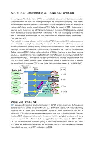
  • 1. ABC of PON: Understanding OLT, ONU, ONT and ODN In recent years, Fiber to the Home (FTTH) has started to be taken seriously by telecommunication companies around the world, and enabling technologies are being developed rapidly. There are two important types of systems that make FTTH broadband connections possible. These are active optical networks (AON) and passive optical networks (PON). By far the majority of FTTH deployments in planning and in deployment use a PON in order to save on fiber costs. PON has recently attracted much attention due to its low cost and high performance. In this post, we are going to introduce the ABC of PON which mainly involves the basic components and related technology, including OLT, ONT, ONU and ODN. First of all, it is necessary to have a brief introduction of PON. In contrast to AON, multiple customers are connected to a single transceiver by means of a branching tree of fibers and passive splitter/combiner units, operating entirely in the optical domain and without power in PON. There are two major current PON standards: Gigabit Passive Optical Network (GPON) and Ethernet Passive Optical Network (EPON). But no matter which type of PONs, they have a same basic topology structure. A Gigabit Ethernet Passive Optical Network (GEPON) system is generally composed of an optical line terminal (OLT) at the service provider's central office and a number of optical network units (ONUs) or optical network terminals (ONTs) near end users, as well as the optical splitter. In addition, the optical distribution network (ODN) is used during the transmission between OLT and ONU/ONT. Optical Line Terminal (OLT) OLT a equipment integrating L2/L3 switch function in GEPON system. In general, OLT equipment contains rack, CSM (Control and Switch Module), ELM (EPON Link Module, PON card), redundancy protection -48V DC power supply modules or one 110/220V AC power supply module, and fans. In these parts, PON card and power supply support hot swap while other module is built inside. The main function of OLT is to control the information float across the ODN, going both directions, while being located in a central office. Maximum distance supported for transmitting across the ODN is 20 km. OLT has two float directions: upstream (getting an distributing different type of data and voice traffic from users) and downstream (getting data, voice and video traffic from metro network or from a long- haul network and send it to all ONT modules on the ODN.
  • 2. Optical Network Unit (ONU) ONU converts optical signals transmitted via fiber to electrical signals. These electrical signals are then sent to individual subscribers. In general, there is a distance or other access network between ONU and end user's premises. Furthermore, ONU can send, aggregate and groom different types of data coming from the customer and send it upstream to the OLT. Grooming is the process that optimises and reorganises the data stream so it would be delivered more efficiently. OLT supports bandwidth allocation that allows making smooth delivery of data float to the OLT, that usually arrives in bursts from the customer. ONU could be connected by various methods and cable types, like twisted-pair copper wire, coaxial cable, optical fiber or Wi-Fi. Optical Network Terminal (ONT) Actually, ONT is the same as ONU in essence. ONT is an ITU-T term, whereas ONU is an IEEE term. They both refer to the user side equipment in GEPON system. But in practice, there is a little difference between ONT and ONU according to their location. ONT is generally on customer premises. Optical Distribution Network (ODN) ODN, an integral part of the PON system, provides the optical transmission medium for the physical connection of the ONUs to the OLTs. Its reach is 20 km or farther. Within the ODN, fiber optic cables, fiber optic connectors, passive optical splitters, and auxiliary components collaborate with each other. The ODN specifically has five segments which are feeder fiber, optical distribution point, distribution fiber, optical access point, and drop fiber. The feeder fiber starts from the optical distribution frame (ODF) in the central office (CO) telecommunications room and ends at the optical distribution
  • 3. point for long-distance coverage. The distribution fiber from the optical distribution point to the optical access point distributes optical fibers for areas alongside it. The drop fiber connects the optical access point to terminals (ONTs), achieving optical fiber drop into user homes. In addition, the ODN is the very path essential to PON data transmission and its quality directly affects the performance, reliability, and scalability of the PON system. Conclusion There are different types of OLT, ONU, ONT equipment for GEPON, which are the new generation PON equipments and mainly applied by telecommunication operators in FTTH project. All these equipment are provided in fiberstore and have the characteristic of high integration, flexible adaption, reliability and capable of providing QOS, web-management as well as flexible enlarging capacity. For more information, please contact us over sales@fs.com. Related Article: AON vs PON Networks: Which One to Choose for FTTH Systems Related Article: Basic Knowledge About GPON SFP Transceivers Related Article: How to Design Your FTTH Network Splitting Level and Ratio?
  • 4. Basic Knowledge About GPON SFP Transceivers Posted on January 17, 2018 By FS.COM GPON stands for Gigabit Passive Optical Network. GPON is one of the key technologies that are being used in fiber-based (FTTx) access networks, including fiber to the home (FTTH), fiber to the business (FTTB), fiber to the curb (FTTC), etc. GPON system contains two main active transmission components, namely optical line termination (OLT) and optical network termination (ONT) or optical network unit (ONU). Modern OLT and ONT/ONU use compact fiber optic modules to achieve the triple- play GPON services. These modules are known as GPON SFP transceivers. This post will give a comprehensive introduction to GPON SFP modules. What Is GPON SFP? GPON SFP is one type of gigabit optical transceivers that are used in GPON system, which is compliant with ITU-T G.984.2 standard. It is a bidirectional module that has SC receptacle and works over simplex single-mode fiber optic cable. A GPON SFP module transmits and receives signals of different wavelengths between the OLT at the Central Office side and the ONT at the end users side. GPON SFPs utilize both the upstream data and downstream data by means of Optical Wavelength Division Multiplexing (WDM). GPON SFP: Class B+ vs. Class C+ GPON SFP transceivers are categorized into GPON OLT SFP and GPON ONT SFP or GPON ONU SFP depending on the devices they are used in. And there are Class B+ GPON SFP and Class C+ GPON SFP. The major differences between them are the transmit power and the receive sensitivity. The table below lists the Tx power and Rx sensitivity of Class B+ GPON SFP and Class C+ GPON SFP. Transceiver Type Class B+ Class C+ Tx power Max. Rx sensitivity Tx power Max. Rx sensitivity GPON OLT SFP 1.5-5 dBm -28 dBm 3-7 dBm -32 dBm OLT SFP Operation Wavelength 1480-1500 nm 1260-1360 nm 1480-1500 nm 1290-1330 nm GPON ONT SFP 0.5-5 dBm -27 dBm 0.5-5 dBm -30 dBm ONT SFP Operation Wavelength 1260-1360 nm 1480-1500 nm 1290-1330 nm 1480-1500 nm By using Class B+ or Class C+ GPON OLT SFP, it can support up to 32 or 64 ONTs at customer premises respectively. And a C+ OLT SFP can be used with B+ ONT SFP as long as the loss budget of the link is appropriate.
  • 5. Figure 1: GPON SFP Class B+ and Class C+. How’s the GPON SFP Different From Conventional BiDi SFP? Although GPON SFP belongs to the gigabit BiDi SFP family, it differs from “normal” BiDi SFPs in some aspects. Here’s a comparison between GPON SFP transceiver and conventional BiDi SFP transceiver. Signal Transmission Mode In terms of conventional gigabit BiDi SFP transceivers that are mainly used in backbone network, the optical transmission mode is point to point (P2P), i.e., they must be used in matched pair. A BiDi usually has LC receptacle instead of SC receptacle. Here’s an illustration of P2P transmission mode. Figure 2: Transmission mode of conventional SFP. The transmission mode of GPON SFP is point to multi-point (P2MP). One GPON OLT SFP at the Central Office communicates with multiple GPON ONT SFPs with the help of fiber optic splitters. This is why we usually see a GPON infrastructure is in a tree shape or a tee shape.
  • 6. Figure 3: Transmission mode of GPON SFP. Transmission Distance The transmission distance of conventional gigabit BiDi SFP can be up to 160 km over single-mode fiber cable when using 1590nm/1510nm and 1510nm/1590nm wavelengths. GPON OLT and ONT/ ONU SFP transceivers support a transmission distance up to 20 km with 1490nm/1310nm and 1310nm/1490nm wavelengths. Benefits of Using GPON SFP Using GPON SFP is considered a more convenient and cost-effective solution for the end customers. And it also reduces the devices that need to be provided by the Internet service provider (ISP). Before the GPON ONT SFP was released and used in GPON networks, the ISP usually needs to install at least an optical modem (a type of ONT with a fiber optic port) and an IP access router, and a Set-Top- Box or video recorder might also be needed if IPTV services are required. The separation of different devices inevitably increased the cost for GPON services. Figure 4: Optical modem with a fiber optic port.
  • 7. The newly used GPON SFP is in smaller size and integrates the triple-play services. It has lower consumption as well. The ISP provides a GPON ONT SFP to the customer. This module is usually installed in the hub/router handed to the customer by the ISP. The customer is also able to unplug the fiber optic patch cable and the GPON ONT SFP from the ISP’s hub/router, and then plug them in his own router/switch that is white-listed by the ISP. Conclusion GPON SFP transceivers are typically used in the two main active transmission components OLT and ONT/ONU in GPON optical networks. They are essential in keeping the high-bandwidth communication between the service provider and the end users over a distance up to 20 km. GPON SFPs are classified into Class B+ and Class C+ and the main differences are their Tx power and Rx sensitivity. This module has simplified the implementation of GPON services. It benefits both the service providers and the end users to some degree. Related Article: Understanding Video SFP Transceiver
  • 8. How to Design Your FTTH Network Splitting Level and Ratio? Posted on June 1, 2016 By FS.COM In Passive Optical Network (PON), optical splitters play an important role in Fiber to the Home (FTTH) networks by allowing a single PON interface to be shared among many subscribers. Optical Splitters are installed in each optical network between the PON Optical Line Terminal (OLT) and the Optical Network Terminals (ONTs) that the OLT serves. During the deployment of fiber to the home passive optical network, usually, we will face some physical access network design problems. This article may help you solve FTTH splitting level and ratio design problems. Choose Optical Splitter: PLC Splitter or FBT Splitter? Before we start to discuss the splitting level and ration design, it’s necessary to choose the right optical splitter type for your FTTH network. There are two types of optical splitters in our current FTTH application—PLC splitter and FBT splitter. Here we have a comparison between these two splitter types: Parameters PLC Splitter FBT Splitter Wavelength Range 1260-1650 nm Single/dual/triple window Splitting Ratio Equal division Equal or non-equal division Dimensions Small Large size for multi-channel Wavelength Sensitivity Low High Cost Low splitting channel, high price Price is lower for small channel spliter As we can see in the table above, with the rapid growth of FTTH worldwide, the requirement for larger split configurations (1x32, 1x64, etc) in these networks has also grown in order to serve mass
  • 9. subscribers, since PLC splitters offer very accurate and even splits with minimal loss in an efficient package, they are offer a better solution for today’s FTTH applications than FBT splitters. FTTH Network Splitting Level Design The PON is the optical fiber infrastructure of an FTTH network. The first crucial architectural decision for the PON network is that of optical splitter placement. The PON splitting may be achieved by centralized splitting (one-level) or by cascaded splittings (two-level or more). A centralized approach typically uses a 1x32 splitter located in a fiber distribution hub (FDH). The splitter is directly connected via a single fiber to a OLT in the central office. On the other side of the optical splitter, 32 fibers are routed to 32 customers’ homes, where it is connected to an ONT. Thus, the PON network connects one OLT port to 32 ONTs. A cascaded approach may use a 1x4 splitter residing in an outside plant enclosure. This is directly connected to an OLT port in the central office. Each of the four fibers leaving this lever 1 splitter is routed to an access terminal that houses a 1x8 level 2 splitter. In this scenario, there would be a also total of 32 fibers (4x8) reaching 32 homes. It is possible to have more than two splitting levels in a cascaded system, and the overall split ratio may vary (1x16 = 4x4, 1x32 = 4x8, 1x64 = 4x4x4). A centralized architecture typically offers greater flexibility, lower operational costs and easier access for technicians. A cascaded approach may yield a faster return-on-investment with lower first-in and
  • 10. fiber costs. Usually, the centralized splitting solution is used in crowded city center or town areas, in order to reduce cost and easy to maintain the optical distributed network (ODN) nodes. In the other hand, two-level and multi-level cascaded splitting solution is used in curb or village places, to cover widely ODN nodes, conserve resources and save the money. FTTH Network Splitting Ratio Design The most common optical splitters deployed in a PON system is a uniform power splitter with a 1:N or 2:N splitting ratio (N=2~64), where N is the number of output ports. The optical input power is distributed uniformly across all output ports. Different ratio splitters may perform differently in your network. Then, how to design your splitting ratio? According to the passage mentioned above, if you choose the centralized splitting solution, you may need to use 1x32 or 1x64 splitter. However, if you choose the cascaded splitting solution, 1x4 and 1x8 splitter may be used more often. Besides, based on our EPON/GPON project experience, when the splitting ratio is 1:32, your current network can receive qualified fiber optic signal in 20 km. If your distance between OLT and ONU is small, like in 5 km, you can also consider about 1:64. Conclusion When to design your FTTH network splitting level, in fact, centralized splitting and cascaded splitting both has its advantages and disadvantages. We had to weight these factors and select an appropriate splitting level for our network. As for splitting ratio design, to ensure a reliable signal transmission, the longer the transmission distance, the lower splitting ratio should be used. FS.COM provides full series 1xN or 2xN PLC and FBT optical splitters which can divide a single/dual optical input(s) into multiple optical outputs uniformly, and offer superior optical performance, high stability and high reliability to meet various application requirements. For more information, you can visit our site to know more details about our PON splitters. Related Article: What Is a Fiber Optic Splitter?
  • 11. Installation Requirements and Network Design Back to Top Optical Distribution Network (ODN) planning is critical to a successful GPON implementation. It is essential to have a well-planned network design to ensure CPEs receive a usable signal, allow for bandwidth capacity and client count on each PON port, and save on costs. This is done by balancing optical power, distance, attenuation, and bandwidth capacity. In the example setup below, a UFiber OLT (UF-OLT or UF-OLT-4) is used as the core of the GPON network, connecting the PON side to the rest of the routing and switching domain. Example GPON topology using an ER-8-XG on the uplink side and a PLC splitter on the PON side.
  • 12. The SFP+ uplink port(s) are used to connect UFiber GPON network to the rest of the routing and switching domain. On the uplink side, we use a high capacity router such as an ER-8-XG, connected to the OLT using 10Gbps SFP+ fiber modules or DAC cables. NOTE: See the UFiber Modules and Cables product page for more information on UBNT branded SFP/SFP+ mo On the PON side, we insert a GPON OLT SFP module (UF-GP-B+ / UF-GP-C+) into the OLT, supporting up to 128 UFiber ONUs per PON port when using PLC splitters. There are various options available to properly connect the OLT to the UFiber ONUs (UF-Nano / UF- LOCO / UF-WIFI). There components that typically make up a GPON network are:  Feeder cable Fiber cable (SC/UPC to SC/APC) connecting the OLT to a distribution point, typically a PLC splitter.  PLC Splitter Fiber splitter that distributes the fiber connection using multiple available split ratios.  Drop cable Fiber cable (SC/APC to SC/APC) providing the final link by connecting the PLC splitter to the ONU.  Adapters or Splices Used to inter-connect the different fiber cables and splitters. The simplest method of connecting UFiber equipment is to use pre-terminated fiber cables with connectors which can simply plug into the other accessories. The official UFiber GPON fiber cable and PLC splitter accessories use SC/UPC and SC/APC connectors which can be used to quickly and easily set up GPON networks. See the Accessories article for more information. There are also other options available such as mechanical and fusion splicing. See the Fiber Connectors and Splicing article for more information. Using either the official accessories or other available fiber equipment, and assuming the power level and attenuation is calculated correctly (see the Calculation section below), the ONU will be connected. The acceptable optical power level range at the ONU is -8 dBm to - 28 dBm. NOTE: The UF-GP-C+ module is capable of higher transmit power which helps overcome attenuation to ensure the ONU. See our UFiber FAQ article for more information. Attenuation and Power Level Calculations Back to Top This section focuses on attenuation, which is the most important factor in designing a GPON network. First, we need to become familiar with sources of attenuation so that we can use them in designing the network and calculation the optical power level (dBm). For example, the UF-GP-B+ module starts with an output power of +3 dBm, while supporting a Rx minimum loss of -8 dBm and a maximum loss of -28 dBm. All of the signals must be within this range. NOTE: There will be zero throughput if the Rx signal is outside of the maximum/minimum loss range With GPO example, where you might see a decrease in throughput if the signal is weak. Common sources of attenuation are:
  • 13.  Length Attenuation occurs over the distance of a fiber run per kilometer (Km) and differs in the downstream (~0.3 dB per Km on 1490 nm) and upstream (~0.5 dB per Km on 1310 nm) frequencies.  Splices Each splice in a fiber optic run accounts for ~0.1 dB. This seems minimal at first, however the count of splices in a single run can add up considerably.  Connectors Each connector accounts for a ~0.6 dB loss. This starts from the SC connector at the UF-GP-B+ module and ~0.6 dB is added for each other connector.  Splitter Splitters are essential in a GPON networks to connect multiple ONUs to a single PON port. See the Splitters section below for more information on using splitters. These are general attenuation values and different vendors may lead to different values depending on the quality of the product. Each source of attenuation will decrease the starting power level to be within the acceptable range for the ONUs. ATTENTION: Connecting a UFiber ONU directly to the UF-GP-B+ in the PON port from the OLT will potentially c and/or the OLT because the power is too high. The acceptable optical power for the UF-Nano is -8 dBm to -28 dBm. The output from the UF-GP-B+ module is attenuation to provide an acceptable level at the ONU. This is also a factor in the upstream optics where the o be too high and cause damage to the UF-GP-B+ module. Upstream and Downstream Calculation Example Back to Top This section focuses on how to calculate the optical power the ONU and OLT will receive. When laying out your fiber distribution network, the goal is to calculate all attenuation in each fiber run to ensure that when connecting the ONU on the customer’s premises it will receive a Rx value of -8 dBm to -28 dBm. It is also important that the received signal from the ONU is also within the same range at the OLT. Like highlighted in the section above, the common sources of attenuation are:  Upstream LengthLoss of ~0.5 dB per Km on 1310 nm.  Downstream LengthLoss of ~0.3 dB per Km on 1490 nm.  SplicesLoss of ~0.1 dB per splice.  ConnectorsLoss of ~0.6 dB per connector.  SplitterLoss of log10(split:ratio) x 10 = Attenuation in dB for each split. The table below show the general attenuation loss for common splitter ratios: Split Formula Loss in dB 1:2 log10 (2) x 10 -3.01dB 1:4 log10 (4) x 10 -6.02dB 1:8 log10 (8) x 10 -9.03dB 1:16 log10 (16) x 10 -12.04dB
  • 14. 1:32 log10 (32) x 10 -15.05dB 1:64 log10 (64) x 10 -18.06dB Using the below network diagram as a guideline, we can use these attenuation sources to end up within the acceptable optical power levels. Power level calculation example using an UF-OLT, a 1:32 PLC splitter and a UF-Nano. Downstream Calculation: Source Loss of Optical Power Calculation Loss in dB Length .3dB x 10Km + .3dB x 6Km -4.8dB Splices .1dB x 2 splices -.2dB Connectors .6dB x 4 connectors -2.4dB
  • 15. Splitter 15.05dB for 1:32 splitter -15.05dB +3 dBm starting power minus loss -19.45dBm Upstream Calculation: Source Loss of Optical Power Calculation Loss in dB Length .5dB x 10Km + .5dB x 6Km -8dB Splices .1dB x 2 splices -.2dB Connectors .6dB x 4 connectors -2.4dB Splitter 15.05dB for 1:32 splitter -15.05dB +3 dBm starting power minus loss -22.65dBm Both the upstream and the downstream signals are within the acceptable range. ATTENTION: The bandwidth will not increase with a better optical power value. Think of this as either on whe the range. The UF-Nano has a built in display showing the optical power levels of both Rx and Tx to easily iden acceptable range. Planning for Capacity vs Client Quantity Back to Top When planning your network it is important to plan for future customers and calculate the available bandwidth on each PON port compared to the client count. There is often a mix of many clients with relatively low bandwidth needs of around 50 to 100 Mbps, and a smaller amount of clients requiring 500 Mbps to 1 Gbps bandwidth. High bandwidth design example: For highest capacity of bandwidth, connecting a single ONU to a single PON port could provide a single client 20km away with the full bandwidth of the PON port. Keep in mind that each of the eight PON ports on the UF-OLT can provide 2.488 Gbps downstream and 1.244 Gbps upstream. In the rare case that a single ONU is used on a single PON port keep in mind that the bandwidth will be limited by the 1 Gbps LAN copper port on the ONU. High capacity design example: For highest capacity of clients. A PLC splitter with a 1:128 ratio connected to a PON port could provide 128 clients with equal bandwidth of about 19 Mbps download and 9 Mbps upload when the clients are all within a range of ~8Km.
  • 16. NOTE: The distance here is decreased from the max 20Km to 8Km due to the attenuation loss ratio of the split splices. The distance could vary when cascading multiple splitters to give the same bandwidth to customers at the Splitters section for more details. Planning with Splitters Back to Top When designing your network it is important to utilize splitters to reduce costs, greater customer reach and for future expansion. The example below shows a good mix of splitters to cover customer locations while still keeping the values in the acceptable range. In this illustration, we will calculate the power from the OLT to the ONU and the ONU to the OLT to be sure each customer will have a usable signal. Remember to always calculate in both the upstream and downstream directions. Example GPON network using multiple PLC splitter ratios. Downstream Calculation:
  • 17. ONU Source Loss of Optical Power Calculation Loss in dB ONU1 Length .3dB x 20Km -6dB Splices .1dB x 4 splices -.2dB Connectors .6dB x 4 connectors -2.4dB Splitters 3.01dB for splitter -3.01dB +3 dBm starting power minus loss -8.81dBm ONU2 Length .3dB x 16Km -4.8dB Splices .1dB x 8 splices -.8dB Connectors .6dB x 6 connectors -3.6dB Splitters 3.01dB + 6.02dB for splitters -9.03dB +3 dBm starting power minus loss -15.23dBm ONU3 Length .3dB x 13Km -3.9dB Splices .1dB x 12 splices -1.2dB Connectors .6dB x 8 connectors -4.8dB Splitters 3.01dB + 6.02dB + 9.03dB for splitters -18.06dB +3 dBm starting power minus loss -24.96dBm Upstream Calculation: ONU Source Loss of Optical Power Calculation Loss in dB ONU1 Length .5dB x 20Km -10dB Splices .1dB x 4 splices -.2dB
  • 18. Connectors .6dB x 4 connectors -2.4dB Splitters 3.01dB for splitter -3.01dB +3 dBm starting power minus loss -12.81dBm ONU2 Length .5dB x 16Km -8dB Splices .1dB x 8 splices -.8dB Connectors .6dB x 6 connectors -3.6dB Splitters 3.01dB + 6.02dB for splitters -9.03dB +3 dBm starting power minus loss -18.43dBm ONU3 Length .5dB x 13Km -6.5dB Splices .1dB x 12 splices -1.2dB Connectors .6dB x 8 connectors -4.8dB Splitters 3.01dB + 6.02dB + 9.03dB for splitters -18.06dB +3 dBm starting power minus loss -27.56dBm