Control Stations - Hazardous Area - Technor AC1WD/DE8BA
•
0 gefällt mir•560 views

Control Stations - Hazardous Area - Technor AC1WD/DE8BA

Empfohlen
Empfohlen
Weitere ähnliche Inhalte
Was ist angesagt?
Was ist angesagt? (20)
Ähnlich wie Control Stations - Hazardous Area - Technor AC1WD/DE8BA
Ähnlich wie Control Stations - Hazardous Area - Technor AC1WD/DE8BA (20)
Mehr von Thorne & Derrick International
Mehr von Thorne & Derrick International (20)
Kürzlich hochgeladen
Kürzlich hochgeladen (20)
Control Stations - Hazardous Area - Technor AC1WD/DE8BA
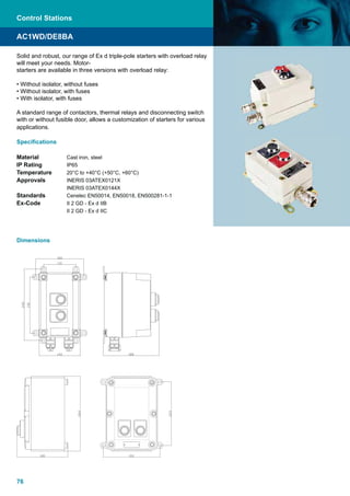
- 1. 76 Solid and robust, our range of Ex d triple-pole starters with overload relay will meet your needs. Motor- starters are available in three versions with overload relay: • Without isolator, without fuses • Without isolator, with fuses • With isolator, with fuses A standard range of contactors, thermal relays and disconnecting switch with or without fusible door, allows a customization of starters for various applications. Specifications Material Cast iron, steel IP Rating IP65 Temperature 20°C to +40°C (+50°C, +60°C) Approvals INERIS 03ATEX0121X INERIS 03ATEX0144X Standards Cenelec EN50014, EN50018, EN500281-1-1 Ex-Code II 2 GD - Ex d IIB II 2 GD - Ex d IIC AC1WD/DE8BA Dimensions Control Stations
- 2. 77 Triple-pole starters Ex d with overload relay without isolator, without fuse Complete with Start and Stop pushbuttons mounted on door Rated current Motor rating Overload range Gas Group and temp. class Basic refer- ence (2) Complete your own reference (1) Weight without cable gland 230V kw 400 V kw 500V kwA A 12 . 0,37 0,75 1 to 1.6 IIB-T6 AC1WD312 •• • • • 5,00 0,37 0,75 1,1 1.6 to 2.5 0,75 1,5 2 2.5 to 4 1,1 2,2 3 4 to 6 1,8 3 4 5.5 to 8 IIC-T3 DE8WH2612 •• • • • 12,00 2,2 4 5,5 7 to 10 3 5,5 7,5 9 to 13 25 4 7,5 10 12 to 18 IIB-T6 AC1WD325 •• • • • 5,50 5,5 11 15 17 to 25 IIC-T3 DE8WH2625 •• • • • 12,00 40 7,5 15 18,5 23 to 32 IIB-T6 DE8BA321340 •• • • • 26,00 11 18,5 22 30 to 40 IIC-T3 DE8WH2640 •• • • • 12,00 65 15 22 30 37 to 50 IIB-T6 DE8BA321365 •• • • • 26,00 15 25 37 48 to 65 IIC-T3 DE8WH2665 •• • • • 12,00 Cable glands Number and position Number Position 2 A, H P1 • • • 2 L, M P2 • • • 3 L, M, H P3 • • • Thread ISO M20 1 F for non armoured cable with clamping module 1 I C 4 F for armoured câble 4 I Without câble gland 5 I Thread ISO M25 1 F for non armoured cable with clamping module 6 I C 4 F for armoured cable 8 I Without câble gland 9 I AC1WD/DE8BA (1) When ordering, please complete your reference. Example: AC1WD321P24I (2) This basic reference, once completed, should be followed by the information: overload relay and voltage For other con¿guration (range, cable gland entries Control Stations WWW.CABLEJOINTS.CO.UK THORNE & DERRICK UK TEL 0044 191 490 1547 FAX 0044 477 5371 TEL 0044 117 977 4647 FAX 0044 977 5582 WWW.THORNEANDDERRICK.CO.UK