SlideShare ist ein Scribd-Unternehmen logo
1 von 43
Downloaden Sie, um offline zu lesen
BRAKE TEST ON A D.C. SHUNT MOTOR


AIM: - To perform brake test on the given D.C. shunt motor and obtain the performance
characteristics of the motor from the test observation.


APPARATUS:

Note: Prepare a list of apparatus required based on the name plate details and circuit
diagram in the following format.

 S.No.   Apparatus           Type                 Range               Quantity
    1.   Ammeter             MC                   (0-2)A              1 NO
    2.   Voltmeter           MC                   0-300V              1 NO
    3.   Rheostat            WW                   370Ω/2A             1 NO
    4.   tachometer          Digital              0-1000rpm           1NO
    .

NAME PLATE DETAILS:

         MACHINE                         MOTOR

          Power                          5HP
          Voltage                        220V
          Current                        20A
          Speed                          1500rpm

PROCEDURE:

1. Connect the circuit diagram as shown in fig.
2. Keep the field regulator Rsh at minimum resistance value.
3. Check that the belt on the pulley is free so that there is no load on the pulley.
4. Start the motor slowly using the starter.
5. Adjust the field current so that the motor runs at its rated speed.
6. Apply load on the pulley gradually in steps, tightening the belt around it.
7. Take the readings of the ammeter and voltmeter connected to the motor and input the
two spring balance readings and the speed at every step.
8. Cool the pulley throughout the loading period by pouring water.
9. Continue the experiment till full load of the motor is reached.
10. Tabulate the observation.
CIRCUIT DIAGRAM :-
TEST READINGS :

Radius of pulley R = ……..m

S.No.      Voltmeter          Ammeter               SpringBalance Speed     in
           Reading “V”        Reading “A”   Readings              RPM
                                             S1 Kg         S2kG       (N)


TABULATE THE RESULTS:

 S.No.     Current    Speed    Input      Output        B.H.P   Efficiency
               I        N         VI(Watt  2IINT(Watts)         Output X 100
                               s)            60                   Input


CALCULATIONS:-

NOTE: Radius of Drum Pulley R

Calculate for every load condition:-

The torque T= 9.81 R ( S1 - S2) N-m

Power output = 2IINT/60 Watts

                     2IINT             1
B.H.P. =                      X
                     60            735.5


GRAPHS:
Plot the Graphs for BHP versus efficiency
Plot the Graphs for BHP versus Torque
Plot the Graphs for BHP versus current
Plot the Graphs for BHP versus speed
Note: All the graphs are shown in Fig,
PRECAUTIONS:

1. Cool the pulley while the experiment is performed.
2. While measuring the radius of the pulley effective radius must be considered.

RESULTS:

Draw the performance characteristics for the D.C. shunt motor on a graph sheet.

VIVA QUESTIONS:

1. What is the back emf of the motor?
2. Why the speed falls as load increases for a D.C. Shunt motor?
3. What are the applications of D.C. Shunt motor?
4. When is the efficiency of the motor maximum?
5. Define commutation.
6. How do you minimize reactance voltage for sparkles commutation?
7. What should be the position of rheostat in the field circuit while starting?
8. What is the nature of load connected across dc motor?
9. What will happen when dc shunt motor is started with load?
10. Give the expressions for various torques in dc motors.
11. What is the effect on speed if part of the field winding is shorted?
BRAKE TEST ON D.C. COMPOUND MOTOR.


AIM: To perform brake test on the given D.C. compound motor and determine the
performance characteristics of the motor.


APPARATUS : Prepare a list of apparatus based on name plate and circuit diagram in
the following format.

 S.No.     Apparatus         Type              Range          Quantity
 01        Ammeter           MC                0-2A           1NO
                                                              1NO
 02        Voltmeter         MC                0-300V
 03        Rheostat          WW                370Ω/1.7A      1NO
                                               0-20A          1NO
 04        Ammeter           MC


NAME PLATE DETAILS:


PROCEDURE:

      1.       Make the connections as shown in fig.5.
      2.       Keep the field rheostat in proper position.
      3.       Check that the belt is loose and the motor is not loaded.
      4.       Start the motor slowly with the starter.
      5.       Note the readings of the voltmeter and ammeter.
      6.        Load the motor in steps by tightening the rope around the brake drum and
      note the readings of the spring Balance voltmeter, ammeter and measure the speed.
      7.       Continue the experiment till full load is reached.
      8.       Slowly reduce the load and stop the motor.
 9. Tabulate the observations
CIRCUIT DIAGRAM :
TEST READINGS:

Radius of Pulley:……………….

 S. No.    S1           S2           V     I        N


CALCULATIONS TABLE:

 S.No. V         I           N   Input     Output       Efficiency


CALCULATIONS:

NOTE: Radius of Drum Pulley R.

Power input = VI watt
                                               2IINT
Power out put = 9.81 x R x (S1 – S2)                       Watts
                                                  60

                2IINT                9.81 x Rx (S1 – S2)
B.H.P. =                         X
(Metric)         60                       735.5

                      Output (Watts)
Efficiency:                                 X 100
                      Input (Watts)


GRAPH:

Plot the graphs for BHP versus Current I
Plot the graphs for BHP versus Speed N
Plot the graphs for BHP versus Torque T
Plot the graphs for BHP versus Efficiencyη .
NOTE: All the graphs are shown in Fig


PRECAUTIONS:

1.   Keep the field rheostat in minimum resistance position while starting the motor.
2.   Start the motor slowly using the starter.
3.   While loading, cool the pulley by pouring cold water

RESULT:

Brake test on the given D.C. compound motor is performed and the performance
characteristics are plotted.

 VIVA QUESTIONS:

1)   Explain the difference between “long shunt” and “short Shunt” compounding?
2)   What are the uses of different types of compound motors?
3)   What is differential compounding? How is it different from cumulative
     compounding?
4)   How do you reverse the direction of motor?
5)   Draw the speed – torque curve for differential. Compound motor
6)   What is flat compounding?
7)   In a dc M/C, windage losses vary with speed in the proportion of …..
8)   Brake test on dc motors is usually restricted to ….HP motors
9)   Why do we pour water in the brake draw during brake test? What is the effect on
     speed of dc compound motor if the series field winding is shorted?
10) How do you minimize iron losses in a dc machine?
Field’s Test on dc series machine.
AIM: To Determine the efficiency of the two given dc series machines which are
mechanically coupled.


Apparatus:

        Name                     Range                    Quantity
        DC Voltmeter             0-300V                     1 No.
        DC Ammeter               0-20A                      2 No.
        Tachometer               0-2000 rpm                 1 No

Name Plate Details:

               Motor                                  Generator

Power      =     5.0 hp.                      Power    =      3.0 kW
Speed      =    1500 rpm.                     Speed    =     1500rpm
Voltage    =     230volts                     Voltage =      220 volts
Current    =     20amps                       Current =      13.6 amps


Procedure
   1.  Note down the ratings of the DC Series motor and DC Series Generator.
   2.     Connect the circuit as shown in the circuit diagram.
   3.     Put a minimum load of 400 watt on the generator.
   4.     Switch on the DC supply and closed the DPST Switch and now vary the DC
          Starter till it holds with current coil.
   5.     Now keep the input DC Voltage constant at 220 volt DC.
   6.     Now increase the load of the Generator up to the rated value of armature current
          and take down the readings of all the meters connected in the circuit.
   7.     Reduce the loads one by one till the motor speed does not exceed 1800 rpm
   8.     Note down the readings on the instruments at different loads.
   9.     Gradually, reduce the armature voltage of the prime mover. Keep a minimum
          load of 400 watt and then switch off the supply
CIRCUIT DIAGRAM :
TABULATIONS:


Observations :
       Armature resistance of the motor Ral = 2.0 ohms.
         Series field resistance of the motor Rsel = 0.8 ohms.
         Armature resistance of the generator Ra2 = 2.0 ohms
         Series field resistance of the generator R se2 = 0.8 ohms.

CALCULATIONS:

V1                =
I1                =
VL                =
IL                =
Power Input Pin = V1 I1
Power output P out = VL IL
Total losses in two machines PL = Pin – P out

        Field copper losses in the motor    =P1= I1 2 Rsel
        Field copper losses in the generator = P2=I12 Rse2

        Armature copper losses in the motor =P3= I12 x Ral
        Armature copper losses in the generator = P4=IL2 x Ra2

Total cu losses in the field and armature of generator and motor is P cu
        Pcu = P1+P2+P3+P4 watts
                                       PL – Pcu
Stray losses in each machine Ws =                 =
                                       2
Motor Efficiency Calculations:

Power input to the motor Pin = V1 I1 2 Rse2

Total losses in the motor W ml = I12 Rsel + I12 + Ws
Motor Output Pout= Pin – Wml
Pout
% Efficiency =             x 100 =               x 100
                  P in
Generator Efficiency Calculations:

       Generator output       Pout (g) = VL IL
       Total losses in the Generator Wgl       = Ws + Il 2 Rse2 + IL2 Ra2

Power input to the generator Pin = Pout (g) + Wgl
                                 Pout
% Efficiency of the generator =           x 100
                                 Pin
HOPKINSON TEST

AIM: To perform Hopkinson test on the given motor generator set and determine the
efficiency of both motor and generator.

APPARATUS:

S.No.   Apparatus        Type      Range        Quantity
01      Ammeter
02      Voltmeter
03      Rheostat

NAME PLATE DETAILES:


PROCEDURE:

1. Make the connection as shown in fig
2. Keep the rheostat in motor field at minimum and generator field at maximum
resistance position And the switch K open.
3. Start the motor generator set slowly with motor starter and adjust the field to rated
value by field rheostat of the motor.
4. Excite the generator by decreasing the generator field rheostat resistance
5. If the voltmeter Vs reads zero then close the paralleling switch K
6. Load the generator in steps by decreasing the field rheostat resistance of the generator
or by increasing the field rheostat resistance of the motor.
7. Take the readings of all the meters for each load and measure the speed in each step.
8. Reduce the excitation of the generator by increasing the field rheostat of the generator
and open the Switch K.
 9. Switch the supply to motor-generator switch.
10. Tabulate the observations.
TEST READINGS:

S.NO       I1          I2               I3           I4        V       VS          VG        N


 S.No.     Motor        Motor            Motor            Generator    Generator        Generator
           Input        Output           Efficiency       Input        Output           Efficiency


MODEL CALCULATIONS:

Input power to motor = V l1 Watts = Total excitation and Stray losses
Generator set = Total excitation and stray losses
                                    Vl 1
Stray losses of each machine =                Watts.
                                     Z
Efficiency of motor    :
Motor input Power = V (l1 + l2)
Output power = input power-Motor armature copper loss – Motor shunt field loss- Stray
loss
                                              Ws

  = V (l1 + l2) – (l1 + l2-l 3)2 Ram – Vl3 -                   Watts
                                                          2
                                Output
% Efficiency =                                   x 100
                                Input
Efficiency of generator
Generator output power = VI2 Watts
Input Power = Output + Gen. Armature copper loss + Generator Shunt field loss + stray
loss

                                                Ws
= VI2 + (l2 + l4)2 Rag + Vl4        +
                                                2

                         Output
% Efficiency =                               X 100

                            Input
8. GRAPHS: Plot the output versus efficiency curves for both the motor and the
   generator as shown in the figure .


PRECAUTIONS:

1)     Keep the rheostats in motor and generator field circuit at proper positions while
starting the motor.
2)    Excessive care while closing the parallel switch K. The voltmeter must read zero
for K to be closed.

RESULT: Hopkinson test on the given D.C. Machine is performed and the performance
characteristics are plotted.

VIVA QUESTIONS:

1). what are the advantages of the test?
2) Can this test be applied to compound machines? Explain
3) When two D.C. machine s are paralleled as is done in this test, which machine acts
as generator and which machine acts as motor?
4). what are the disadvantages of this test?
5) What are heat run tests?
6) Hopkinson’s test is a ………..test.
7). Hopkinson’s test on D.C. Machines is conducted at ….load.
8). The armature voltage control of D.C. motor provides …… drive.
MAGNETIZATION CHARACTERISTIC OF A D.C. SHUNT GENERATOR.


AIM: To determine experimentally the magnetization or open circuit characteristic of a
generator and determine the critical field resistance and critical speed

APPARATUS:
Prepare a List of the apparatus required based on the name plate ratings and Circuit
diagram in the following format.

S. No.     Apparatus                   Type                 Range            Quantity
   1.      Rheostats
   2.      Voltmeters
   3.      Ammeters
   4.      Tachometers
   5.      Knife switch


NAME PLATE DETAILS:

 Specifications            Motor             Generator
 Rating
 Field current
 Load current
 Voltage


PROCEDURE:

1. Connect the circuit as shown in the fig
2. Set the potential divider to zero output keeping motor field rheostat in minimum
resistance position
3. Switch on the supply and start the motor with the help of the starter. Adjust the speed
of the motor generator set to the rated speed of the generator by controlling the motor
field resistance the set speed is to be maintained constant throughout the experiment Note
down the voltmeter reading at zero field current (lf). Increase the field current lf
uniformly in steps, by changing the potential divider tapping, simultaneously note down
the field current (lf) and the terminal voltage (E) across the generator armature terminals.
4. Continue the experiment till saturation of the field is reached.
5. Continue the experiment for decreasing values of If in steps by decreasing the tapping
of potential divider.
CIRCUIT DIAGRAM:
TEST READINGS:

 Increasing lf                     Decreasing If
 S.No.     lf           E          S.No.        Lf           E


Critical Field Resistance: It is that value of the field resistance at which the D.C. shunt
generator will fail to excite.

Critical Speed: It is that speed for which the given shunt field resistance becomes the
critical field resistance. Critical field resistance is obtained by plotting the OCC as in
fig.2 and determining the slope of the tangent to the linear position of the curve from the
origin. While drawing the tangent, the initial position of the O.C.C is neglected.


OX is the tangent
Critical Field resistance

Rc = BC
     AB

OY is the shunt Field resistance line

The Critical speed Nc = YZ       x Rated Speed.
                        XZ

Rated speed is the speed at which the OCC is obtained.


PRECAUTIONS:
1. Perform the experiment at constant speed.
2. Readings are to be taken for uniformly increasing and then uniformly decreasing field
current.
3. Check must be made for residual magnetism otherwise; the field terminals may be
required to be reversed.
RESULT:
 Magnetization characteristics are observed.

VIVA QUESTIONS:

1. Why is the magnetization characteristic different for increasing and decreasing of
values of lf?
2. What is the purpose of starter for the motor?
3. Why is the speed maintained constant during the experiment?
4. Why is the motor field resistance kept to a minimum while starting the motor?
5. What is residual magnetism?
6. Define critical resistance.
7. Define critical speed.
8. How do you determine critical resistance with help of O.C.C.?
9. Explain magnetization curve.
10. How do you determine critical speed graphically?
11. Define coercive force
12 Explain hysteresis phenomenon.
SEPARATION OF LOSSES IN A D.C. SHUNT MACHINE


AIM: To perform suitable tests on the given D.C. shunt machine and determine from the
experiment the stray losses and separates these into friction, hysterics and eddy current
losses.

APPARATUS:
Prepare a list of apparatus based on name plate and circuit diagram in the following
format.

 S.No. Apparatus              Type          Range              Quantity
 01    Ammeter                MC            0-2A               2NO
                              MC            0-300V             1NO
 02       Voltmeter
 03       Rheostat            WW            370Ω/1.7A          2NO
 04       tachometer          digital       0-2000rpm          1NO


NAME PLATE DETAIS:


PROCEDURE:

1). Make the connections as per the circuit diagram as shown in FIG.
2). Start the motor slowly using starter keeping the field and armature rheostats in
      Minimum and maximum position respectively.
3) Adjust the field current to the rated value at no- load
4) Reduce the armature circuit resistance in steps, increasing the speed.
5) Take the readings of voltmeter, ammeter and speed at constant field current.
6) Continue the experiment till maximum speed is obtained by cutting out the complete
resistance in armature circuit (Do not exceed rated speed)
7) Bring the armature rheostat back to full resistance (initial) position.
8). Repeat the experiment with a reduced field current. (75% rated excitation) stop the
motor.
9) Stop the motor
10) Measure the armature resistance by voltmeter-ammeter method using the circuit
diagram as shown in Fig.
11). Tabulate the readings.
TEST READINGS :

Field Current (lf1)                                           A

 S.No. N       V      lf      la

                                   Field Current (lf2)        A

 S.No. N       V      lf      la


CALCULATIONS:
IF1…………….A                                   IF2……………………A

 S.No. V-la Ra= W=Ea           W            S.No.        V-la Ra=   W=Ea la   W
          Eb    la             N                             Eb               N


CIRCUIT DIAGRAM:
GRAPH:

Plot W/N Versus N for both the field excitations:

From the graph find out
B1 + D= bc/ab
B + D = ef/de

Determine
A+C and A1 + C
Solve for A, A1, B, B1, C, D.

RESULT : At rated speed the various losses are results
    Hysteresis loss     = ………………W
    Eddy Current loss = ……………… W
    Friction loss = …………………… W
    Wind age loss = ………………..              W

PRECAUTIONS:
  1. Keep the field current constant during each part of the experiment.
  2. Check the position of the rheostat positions before stating the motor.

VIVA QUESTIONS:

1).   How Hysteresis losses occur in a D.C. Machine?
2)    Where are eddy current losses occurring in a D.C. Machines?
3)    How are the magnetic losses minimized?
4)    How is brush contact resistance loss taken into consideration in practice?
5)    Give the expression for hysteresis loss.
6)    What is the effect of armature reaction?
7)    How do you minimize cross magnetizing effect of armature reaction.
8)    Differentiate MNA & GNA
9)    Which test gives us stray losses?


                                  SWINBURNE’S TEST

  AIM: To perform Swinburne’s test on the given D.C. machine and predetermine it
efficiency at any desired load both as motor and as generator.
ARATUS REQUIRED: Prepare a list of apparatus based on name plate and circuit
diagram in the following format.

 S. No.   Apparatus              Type            Range          Quantity
 01       Ammeter                MC              0-2A           2NO
 02       Voltmeter              MC              0-300V         1NO
 03       Rheostat               WW              370Ω/1.7A      1NO
 04       Ammeter                MC              0-20A          1NO
 05       Tachometer             digital         0-10000rpm     1NO
NAME PLATE DETAILS:

             Voltage         :

             Field Current:…………………

             Load Current:……………………….

             Speed:………………………


PROCEDURE:

1) Make the connections as in fig
2) Start the D.C. motor with the starter slowly and bring it to rated speed.
3) Take the no load readings of input current, armature current, field current and input
voltage.
4) Stop the machine.
5). Measure the armature resistance using circuit diagram as shown in Fig.
6). Measure the field resistance using the circuit diagram as shown in Fig .by replacing
the armature by shunt field winding


Tabular columns:
Measurement of Ra                                   Measurement of Rsh

S.No. Va       Ia               Va         S.No.    Vsh     Ish            Vsh
                         Ra =                                      Rsh =
                                La                                         lsh


Average Ra (t1) = ……………….. Ω                    Average Rsh (t1) = ……………….Ω

 S.NO               V(volts)         IL(AMPS)        If(amps)        N(rpm)


MODEL CALCULATIONS:
CIRCUIT DIAGRAM


GRAPH :
PRECAUTIONS:
1   Keep the field rheostat at the minimum resistance position and armature rheostat in
maximum resistance position while starting the motor.
2.    The experiment is to be performed only at no-load.
3.    After starting the motor the armature rheostat must be fully cut- off.
RESULT:
         Efficiency at no load condition calculated and performance curves drawn.
VIVA QUESTIONS

1.    What are the advantages of the Swinburne test?
2.    Why Swinburne test cannot be performed on series machines? Explain.
3.    How do you obtain accurate measurements in this experiment?
4.    How do you reverse the direction of motor?
5.    Draw the speed – torque for diff. Compound motor.
6.    What is Flat Compounding?
7     Ia a dc m/c, winding losses varies with speed in the proportion of -----------
8.    Brake test on D.C. Motors are usually restricted to ---------- HP motors.
9.    Why do we pour water in the brake drum during brake test?
10.     What is the effect on speed of d.c. compound for if the series field winding is
shorted.
11.   How do you minimize iron losses in a dc machine?


                    SPEED CONTROL OF D.C. SHUNT MOTOR
AIM: To determine the speed characteristics of D.C shunt motor by (i) field control and
     (ii) armature control:

     APPARATUS REQUIRED:

     Note: Prepare a list of apparatus required based on name plate ratings and circuit diagram
     in the following Format.

      S.No.    Apparatus                   Type                Range             Quantity
       01      Ammeter               MC                   (0-2)A               1NO
          02   Voltmeters            MC                   (0-300)V             1NO
          03   Rheostat              WW                   370Ω/1.7A            2NO
          04   Tachometer            Digital              0-10000rpm           1NO


     NAME PLATE DETAILS:


               Rating …………………………………….                                Load Current ………………………..

               Voltage …………………………………..                               Speed ………………………………...


     PROCEDURE:

1.   Make connections as per the circuit diagram fig.
     2.    Keep the field rheostat in the minimum resistance position and the armature
           resistance in the maximum resistance position.
     3.    Start the motor by closing the switch and operating the starter slowly.
     4.    For the field control method, adjust the rheostat R2 so the voltmeter reads about 200
           volts.
     5.    Increase the field resistance in steps there by decreasing the field current. Note
           down the values of lsh, the shunt field current and the speed. Take enough readings
           (8 to 10) to obtain a good curve.
     6.    For armature control, keep the field rheostat at a selected field current value note
           the rated field current?
                 7. Decrease the armature resistance from maximum position in steps
                    keeping the     field current at the set value. Note down the speed for
                    each value of armature voltage.
CIRCUIT DIAGRAM :


TEST READINGS:
Field control (Va=……)             Armature Control (lf=…………..)
 S.NO. Ish          N               S.No.                Va                  N


GRAPH:

Plot Ish Vs N and VA (armature voltage) α N graphs.

PRECAUTIONS:
1. Keep the armature and field rheostats at proper positions while starting the motor.
2. Maintain constant field current for armature control and constant armature voltage for
   field control part of the experiment.
RESULT:

The variation of speed with armature voltage and field current in case of D.C. shunt
motor is studied.

VIVA QUESTIONS:

1. What will happen if the shunt field is open during running?
2. What is the purpose of No volt coil in a D.C. Motor?
3. How do you change the direction of rotation of a D.C. Shunt motor?
4. What are the methods of speed control in a dc shunt motor?
5. In which method of speed control, above the base speed can be achieved, why?
6. List the merits and demerits of armature voltage control method.
7. What is the necessity of starter?
8. What is the function of OLR coil in dc starter?
9. What is the advantage of 4- point starter over 3-point starter?
10. Which is the precise method of speed control of dc motors?
LOAD TEST ON D.C. SERIES GENERATOR

AIM: To perform load test on a D.C. series generator and to draw the internal and
external characteristics.
APPARATUS:
Note: Prepare a list of apparatus required based on name plate ratings and circuit diagram
in the following format.

    S.No.        APPARATUS             TYPE         RAANGE               QUANTITY
      1.         Rheostats             WW           370Ω/1.7A            1NO
                                                    0-300V               1NO
      2.         Voltmeters            MC
      3.         Ammeters              MC           (0-20)A              1NO
      4.         Tachometers           Digital      0-10000rpm           1NO


NAME PLATE DETAILS:

 Parameter                     Motor                         Generator
 Rating
 Load current
 Field current
 Speed


PROCEDURE
1). Connect the circuit as shown in fig.
2) Keep the motor field rheostat in minimum resistance position and do not connect any
load on the generator
3) Switch on the supply and start the motor with the help of starter.
4). Adjust the speed by controlling the motor field resistance.
5) Now, switch ON the load and for different values of load, note the ammeter and
voltmeter readings.
6). after loading the generator up to the rated value gradually reduce the load in steps and
switch off the supply.
CIRCUIT DIAGRAM :-
                 STARTER
                 L   A       Z

    +
    -                                                                     0- 30A
                                                      Y       YY          + A -

        220 v,           A                                                Load
                                     Z                                   Rheostat
        D.C          M                           A
        supply                                                   +
                                             G                       V
                         AA                                      -
                                    ZZ           AA


   --


                             Fig. 10.1 : Load test on d.c. Series generator


TEST READINGS :
S.NO               IL(AMPS)              V(VOLTS)              Eg(VOLTS)


Model calculations:
V= Eg – la (Ra + Rse)
Where
  V     = Terminal voltage
  Eg = Emf generated in the armature (Volts)
  La = Armature current (A) = lse = lL
  Ra = Armature resistance (Ω)
  Rse = Series field resistance (Ω)


PRECAUTIONS:

1).    Loose connections are to be avoided.
2).    Remove the load gradually in steps and switch OFF the motor
RESULT:

Performance characteristics are observed.


VIVA QUESTIONS.
1)   How the internal characteristics are derived from external characteristics?
2)   What are reasons for the failure of a D.C. series generator to build up voltage?
3)   What is meant by critical resistance of a D.C. series generator?
4)   What is the necessity of starter in D.C. Motors?
5)   What material used for brushes, why?
 6) Why are external characteristic lies below the internal characteristic in D.C. Shunt
generators?
7)   What is the critical load resistance?
8)   How do you control the speed of D.C. Motor?


                    LOAD TEST ON D.C. SHUNT GENERATOR
AIM: To perform load test on D.C. Shunt Generator and determine there from the
internal and external characteristics of the generator.

APPARATUS: Prepare a list of apparatus based on name plate and circuit diagram in
the following format.
  S.No. Apparatus              Type              Range         Quality
    01    Ammeters       MC                  (0-2)A         1NO

     02    Voltmeters           MC                    0-300V            1NO

     03    Rheostats            WW                    370/1.7A          2NO

     04    Tachometer           Digital               0-10000rpm        1NO


NAME PLATE RATINGS:-
Motor                Generator
Power    5HP         Power                           3KW
 Voltage        220V            Voltage              220V
 Current         20A            Current               13.6A
 Speed           1500rpm        Speed                1500rpm


PROCEDURE:

1)    Make the connection as shown in the circuit diagram as shown in the fig Start the
      motor with the help of the starter.
2)    Adjust the field regulator of the motor so that the generator runs at its rated speed.
3)    Adjust the generator field regulator so that rated voltage is obtained at its terminals.
4)    Gradually apply the load in steps and note down the readings of the load as given
      on the name plate of the generator. Keep the speed constant at its rated value by
      adjusting motor field regulator throughout experiment.
5)    Plot the external load characteristic from the observations.
6)    Determine the armature resistance experimentally using the circuit diagram in fig.
7)    Take at least 6 readings of voltmeter and armature by varying the load resistance
      and determine the average value of the armature resistance.
OBSERVATION TABLE:
 Speed ………R.P.M.
 S. No.   Load Current                     Terminal Voltage             Field Current
               IL                                V                            If


CALCULATIONS:

Average value of armature resistance Ra = ----------Ω

 S.NO.             l a = l L + LF              E = V + La Ra


GRAPHS :

1). Plot the external or load characteristic from the table.1 (lL Vs V curve )
2) Plot the internal characteristic or total characteristic from Table No.2 (la Vs E Curve)
PRECAUTIONS:

1) While starting the motor, field regulator (rheostat) must be in minimum position
2) While loading the generator, at every step speed of the generator must be maintained.
At rated value by adjusting the motor field regulator.
3). Decrease the speed before removing the load after the experiment is completed at full
load.
4) Do not over load the generator
RESULTS:

Internal and external characteristics are plotted by conducting load test on the given D.C.
Shut generator.

VIVA QUESTIONS:

1) If the shunt generator fails to buildup what could be the reason for it. Explain how
this can be over come
2) What is meant by armature reaction?
3) Why are the characteristics of the shunt generator drooping?
4) DC Generators are normally designed for max efficiency around ….load
5) What will happen when R-C load is connected across armature?
6) For a properly designed dc generators the over all efficiency could be of the order of
-----%
7) Define commercial & electrical efficiencies for dc generators
8) Which losses in a dc generator vary significantly with the load current?
9) Draw the internal and external characteristics for a dc shunt generator.
CIRCUIT DIAGRAM:


            LOAD TEST ON DC COMPOUND GENERATOR.
AIM: To conduct a load test on given DC compound generator and to plot the internal
and external characteristics of the generator.

APPARATUS REQUIRED:

 S.No      Apparatus             Type        Range              Quantity
 01        Ammeter               MC          0-2A               1NO
                                                                1NO
 02        Voltmeter             MC
                                             0-300V
 03        Rheostat              WW          370Ω/1.7A          2NO
 04        Ammeter               MC          0-20A              1NO

 05        Tachometer            digital     0-10000rpm         1NO


NAME PLATE DETAILS:

 Parameter                   Motor                            Generator
 Rating                      5HP                              3KW
 voltage
                             220V                             220V
 Load current                20A                              13.6A
 Speed
                             1500RPM                          1500RPM


PROCEDURE:

Connect the circuit as per the circuit diagram shown in fig
1. Keep the field regulator of the motor in the minimum resistance position and regulator
of the generator in the maximum resistance position.
2. Switch on the supply and start the motor with the help of its starter.
3. Adjust the field regulator of the motor such that it runs its rated speed given on the
name plate.
4. Adjust the armature regulator of the generator to build up its rated voltage given on its
name plates on no load.
5. Note down the no loads of ammeter and volt meter in tabular form.
6. Increase the load gradually in steps and tabulate the readings
7. Plot the external characteristics is load current Vs terminal voltage.
8 Connect the generator for differentially compounding, repeat the process and plot the
external characteristics.
CIRCUIT DIAGRAM:


OBSERVATIONS:
S.NO    V(volts)   IL(AMPS)   If(AMPS)   Ia=IL+If   Eg=V+Ia(Ra+Rf)
GRAPHS:-
1). Plot the external or load characteristics from table 1. (IL Vs V curve)
2).   Plot the internal characteristics or total characteristics from table 2. (lL Vs Eb curve )


PRECAUTIONS:
1).Loose connections must be avoided.
2) The generator must be seen at constant speed through out the experiment.
3) The position of the starter must be checked before giving supply
4) The resistance of the field regulator of the motor must be adjusted to minimum
resistance position at the time of switching on the supply.
 5).the resistance of the field regulator of the generator must be adjusted maximum
resistance at the beginning.
RESULTS:
Internal and external characteristics are plotted by conducting load test on the given DC
compound generator.


VIVA QUESTIONS:-
1). How many field windings are there in a compound generator? What are they?
2).   what does compounding mean?
3).   Draw the external characteristics for a level compound generator
4).   in a compound wound generator which of the two fields dominate
5) Discuss the performance of a DC compound generator using only one field winding
at a time.
6).   what is meant by commutation?
7)    What are the different methods oaf obtaining spark less or good commutation?
8)    Why do you perform load test?
9)    Differentiate cumulative & differential compound generators.
10). Give at least three applications of dc compound generators.
11) What is the critical resistance’s in a dc shunt machine?

Weitere ähnliche Inhalte

Was ist angesagt?

Gsm based transformer fault detection system
Gsm based transformer fault detection systemGsm based transformer fault detection system
Gsm based transformer fault detection systemKabilesh K
 
DC compound motor ppt
DC compound motor pptDC compound motor ppt
DC compound motor pptSahib Ullah
 
BLDC Motor Speed Control with RPM Display and PWM
BLDC Motor Speed Control with RPM Display and PWMBLDC Motor Speed Control with RPM Display and PWM
BLDC Motor Speed Control with RPM Display and PWMEdgefxkits & Solutions
 
Power System Modelling And Simulation Lab
Power System Modelling And Simulation LabPower System Modelling And Simulation Lab
Power System Modelling And Simulation LabSachin Airan
 
Unit 2.Converter and Chopper fed Dc drives
Unit 2.Converter and Chopper fed Dc drivesUnit 2.Converter and Chopper fed Dc drives
Unit 2.Converter and Chopper fed Dc drivesraviarmugam
 
Chapter 3 transmission line performance
Chapter 3  transmission line performanceChapter 3  transmission line performance
Chapter 3 transmission line performancefiraoltemesgen1
 
Exp 2 (1)2. To plot Swing Curve for one Machine System
Exp 2 (1)2.	To plot Swing Curve for one Machine SystemExp 2 (1)2.	To plot Swing Curve for one Machine System
Exp 2 (1)2. To plot Swing Curve for one Machine SystemShweta Yadav
 
180degree conduction mode of 3 phase inverter
180degree conduction mode of  3 phase inverter180degree conduction mode of  3 phase inverter
180degree conduction mode of 3 phase inverterdineshanand810
 
Et201 chapter3 sinusoidal steady state circuit analysis
Et201 chapter3 sinusoidal steady state circuit analysisEt201 chapter3 sinusoidal steady state circuit analysis
Et201 chapter3 sinusoidal steady state circuit analysisnursheda
 
Speed control of Three phase Induction motor using AC voltage regulator
Speed control of Three phase Induction motor using AC voltage regulatorSpeed control of Three phase Induction motor using AC voltage regulator
Speed control of Three phase Induction motor using AC voltage regulatorShivagee Raj
 

Was ist angesagt? (20)

Gsm based transformer fault detection system
Gsm based transformer fault detection systemGsm based transformer fault detection system
Gsm based transformer fault detection system
 
DC compound motor ppt
DC compound motor pptDC compound motor ppt
DC compound motor ppt
 
BLDC Motor Speed Control with RPM Display and PWM
BLDC Motor Speed Control with RPM Display and PWMBLDC Motor Speed Control with RPM Display and PWM
BLDC Motor Speed Control with RPM Display and PWM
 
Power System Modelling And Simulation Lab
Power System Modelling And Simulation LabPower System Modelling And Simulation Lab
Power System Modelling And Simulation Lab
 
Unit 2.Converter and Chopper fed Dc drives
Unit 2.Converter and Chopper fed Dc drivesUnit 2.Converter and Chopper fed Dc drives
Unit 2.Converter and Chopper fed Dc drives
 
DC machines PPT.pptx
DC machines PPT.pptxDC machines PPT.pptx
DC machines PPT.pptx
 
Two Quadrant chopper
Two Quadrant chopperTwo Quadrant chopper
Two Quadrant chopper
 
Chapter 3 transmission line performance
Chapter 3  transmission line performanceChapter 3  transmission line performance
Chapter 3 transmission line performance
 
Exp 2 (1)2. To plot Swing Curve for one Machine System
Exp 2 (1)2.	To plot Swing Curve for one Machine SystemExp 2 (1)2.	To plot Swing Curve for one Machine System
Exp 2 (1)2. To plot Swing Curve for one Machine System
 
180degree conduction mode of 3 phase inverter
180degree conduction mode of  3 phase inverter180degree conduction mode of  3 phase inverter
180degree conduction mode of 3 phase inverter
 
DC GENERATOR
DC GENERATORDC GENERATOR
DC GENERATOR
 
Electrical machines lecture notes
Electrical machines lecture notesElectrical machines lecture notes
Electrical machines lecture notes
 
THE POWER FACTOR
THE POWER FACTOR THE POWER FACTOR
THE POWER FACTOR
 
Et201 chapter3 sinusoidal steady state circuit analysis
Et201 chapter3 sinusoidal steady state circuit analysisEt201 chapter3 sinusoidal steady state circuit analysis
Et201 chapter3 sinusoidal steady state circuit analysis
 
dc Generator Ppt
dc Generator Pptdc Generator Ppt
dc Generator Ppt
 
Svpwm
SvpwmSvpwm
Svpwm
 
SWINBURNE’S TEST
SWINBURNE’S TESTSWINBURNE’S TEST
SWINBURNE’S TEST
 
Gto & igct
Gto & igctGto & igct
Gto & igct
 
Unit 4 cycloconverter
Unit 4 cycloconverterUnit 4 cycloconverter
Unit 4 cycloconverter
 
Speed control of Three phase Induction motor using AC voltage regulator
Speed control of Three phase Induction motor using AC voltage regulatorSpeed control of Three phase Induction motor using AC voltage regulator
Speed control of Three phase Induction motor using AC voltage regulator
 

Andere mochten auch

Performance of dc motors experiment 2
Performance of dc motors experiment 2Performance of dc motors experiment 2
Performance of dc motors experiment 2Karimi LordRamza
 
ee2259-lab-manual
 ee2259-lab-manual ee2259-lab-manual
ee2259-lab-manualsurya721327
 
Testing of DC Motors
Testing of DC MotorsTesting of DC Motors
Testing of DC MotorsPritam Ghosh
 
Configure h base hadoop and hbase client
Configure h base hadoop and hbase clientConfigure h base hadoop and hbase client
Configure h base hadoop and hbase clientShashwat Shriparv
 
Miquel Martí i Pol
Miquel Martí i PolMiquel Martí i Pol
Miquel Martí i PolQuim Civil
 
Spring overview & architecture
Spring  overview & architectureSpring  overview & architecture
Spring overview & architecturesaurabhshcs
 
Ea conference st albert feb 2014
Ea conference  st albert feb 2014Ea conference  st albert feb 2014
Ea conference st albert feb 2014tobylscott
 
Ch2 2014 Kristen Ricker Nixa High School
Ch2 2014 Kristen Ricker Nixa High School Ch2 2014 Kristen Ricker Nixa High School
Ch2 2014 Kristen Ricker Nixa High School rickerkristen
 
Aspire one series service guide
Aspire one series service guideAspire one series service guide
Aspire one series service guideSetyo Prasadja
 
2012 06 FGV Custo Mão de Obra Encargos Sociai Brasil
2012 06   FGV Custo Mão de Obra Encargos Sociai Brasil2012 06   FGV Custo Mão de Obra Encargos Sociai Brasil
2012 06 FGV Custo Mão de Obra Encargos Sociai BrasilSiamfesp Sindicato
 
Tarif jne-oke-2013-bdg-1-juni-2013
Tarif jne-oke-2013-bdg-1-juni-2013Tarif jne-oke-2013-bdg-1-juni-2013
Tarif jne-oke-2013-bdg-1-juni-2013ridwansf2
 
Global and china obd telematics industry report, 2014 2015
Global and china obd telematics industry report, 2014 2015Global and china obd telematics industry report, 2014 2015
Global and china obd telematics industry report, 2014 2015ResearchInChina
 
TBEX15 Asia Thailand Sara Meaney
TBEX15 Asia Thailand Sara MeaneyTBEX15 Asia Thailand Sara Meaney
TBEX15 Asia Thailand Sara MeaneyTBEX
 

Andere mochten auch (20)

Performance of dc motors experiment 2
Performance of dc motors experiment 2Performance of dc motors experiment 2
Performance of dc motors experiment 2
 
ee2259-lab-manual
 ee2259-lab-manual ee2259-lab-manual
ee2259-lab-manual
 
testing of dc machine
testing of dc machinetesting of dc machine
testing of dc machine
 
Corrected1
Corrected1Corrected1
Corrected1
 
Testing of DC Motors
Testing of DC MotorsTesting of DC Motors
Testing of DC Motors
 
Configure h base hadoop and hbase client
Configure h base hadoop and hbase clientConfigure h base hadoop and hbase client
Configure h base hadoop and hbase client
 
1st Grade Unit 6: Blue jay finds a way
1st Grade Unit 6: Blue jay finds a way1st Grade Unit 6: Blue jay finds a way
1st Grade Unit 6: Blue jay finds a way
 
Miquel Martí i Pol
Miquel Martí i PolMiquel Martí i Pol
Miquel Martí i Pol
 
Spring overview & architecture
Spring  overview & architectureSpring  overview & architecture
Spring overview & architecture
 
Ea conference st albert feb 2014
Ea conference  st albert feb 2014Ea conference  st albert feb 2014
Ea conference st albert feb 2014
 
Ch2 2014 Kristen Ricker Nixa High School
Ch2 2014 Kristen Ricker Nixa High School Ch2 2014 Kristen Ricker Nixa High School
Ch2 2014 Kristen Ricker Nixa High School
 
Aspire one series service guide
Aspire one series service guideAspire one series service guide
Aspire one series service guide
 
2012 06 FGV Custo Mão de Obra Encargos Sociai Brasil
2012 06   FGV Custo Mão de Obra Encargos Sociai Brasil2012 06   FGV Custo Mão de Obra Encargos Sociai Brasil
2012 06 FGV Custo Mão de Obra Encargos Sociai Brasil
 
Ususnmptn2011
Ususnmptn2011Ususnmptn2011
Ususnmptn2011
 
Tarif jne-oke-2013-bdg-1-juni-2013
Tarif jne-oke-2013-bdg-1-juni-2013Tarif jne-oke-2013-bdg-1-juni-2013
Tarif jne-oke-2013-bdg-1-juni-2013
 
C Programming
C ProgrammingC Programming
C Programming
 
Global and china obd telematics industry report, 2014 2015
Global and china obd telematics industry report, 2014 2015Global and china obd telematics industry report, 2014 2015
Global and china obd telematics industry report, 2014 2015
 
TBEX15 Asia Thailand Sara Meaney
TBEX15 Asia Thailand Sara MeaneyTBEX15 Asia Thailand Sara Meaney
TBEX15 Asia Thailand Sara Meaney
 
англійська мова 3 кл підручник
англійська мова 3 кл підручниканглійська мова 3 кл підручник
англійська мова 3 кл підручник
 
Visual Network Analysis
Visual Network AnalysisVisual Network Analysis
Visual Network Analysis
 

Ähnlich wie 53669836 brake-test-on-a-d (20)

Electrical machines-lab-i-ee0209
Electrical machines-lab-i-ee0209Electrical machines-lab-i-ee0209
Electrical machines-lab-i-ee0209
 
Occ of dc generator
Occ of dc generatorOcc of dc generator
Occ of dc generator
 
269010454 electrical-machines-lab-manual-for-petrochemaical
269010454 electrical-machines-lab-manual-for-petrochemaical269010454 electrical-machines-lab-manual-for-petrochemaical
269010454 electrical-machines-lab-manual-for-petrochemaical
 
Experiment 2 AC Machines
Experiment 2 AC MachinesExperiment 2 AC Machines
Experiment 2 AC Machines
 
Control_System_Lab.pdf
Control_System_Lab.pdfControl_System_Lab.pdf
Control_System_Lab.pdf
 
Field test
Field test Field test
Field test
 
CIRCLE DIAGRAM ON 1-PHASE INDUCTION MOTOR
CIRCLE DIAGRAM ON 1-PHASE INDUCTION MOTORCIRCLE DIAGRAM ON 1-PHASE INDUCTION MOTOR
CIRCLE DIAGRAM ON 1-PHASE INDUCTION MOTOR
 
CONTROL SYSTEM LAB MANUAL
CONTROL SYSTEM LAB MANUALCONTROL SYSTEM LAB MANUAL
CONTROL SYSTEM LAB MANUAL
 
Ee 791 drives lab maual
Ee 791 drives lab maualEe 791 drives lab maual
Ee 791 drives lab maual
 
Ped lab 2017 reg manual
Ped lab 2017 reg manualPed lab 2017 reg manual
Ped lab 2017 reg manual
 
Dc motor
Dc motorDc motor
Dc motor
 
16 engine electrical
16 engine electrical16 engine electrical
16 engine electrical
 
Lm555
Lm555Lm555
Lm555
 
Third Lesson Induction Motor
Third Lesson Induction MotorThird Lesson Induction Motor
Third Lesson Induction Motor
 
Third Lesson Induction Motor
Third Lesson Induction MotorThird Lesson Induction Motor
Third Lesson Induction Motor
 
Ee2259 lab-manual
Ee2259 lab-manualEe2259 lab-manual
Ee2259 lab-manual
 
Pe lab converted
Pe lab convertedPe lab converted
Pe lab converted
 
Eso203 a ha10
Eso203 a ha10Eso203 a ha10
Eso203 a ha10
 
Design 1st & Hillcrest Petroleum Advanced Energy - Generator Testing FTC Report
Design 1st & Hillcrest Petroleum Advanced Energy - Generator Testing FTC ReportDesign 1st & Hillcrest Petroleum Advanced Energy - Generator Testing FTC Report
Design 1st & Hillcrest Petroleum Advanced Energy - Generator Testing FTC Report
 
ELEKTRA_new
ELEKTRA_newELEKTRA_new
ELEKTRA_new
 

Kürzlich hochgeladen

👉Chandigarh Call Girls 👉9878799926👉Just Call👉Chandigarh Call Girl In Chandiga...
👉Chandigarh Call Girls 👉9878799926👉Just Call👉Chandigarh Call Girl In Chandiga...👉Chandigarh Call Girls 👉9878799926👉Just Call👉Chandigarh Call Girl In Chandiga...
👉Chandigarh Call Girls 👉9878799926👉Just Call👉Chandigarh Call Girl In Chandiga...rajveerescorts2022
 
How to Get Started in Social Media for Art League City
How to Get Started in Social Media for Art League CityHow to Get Started in Social Media for Art League City
How to Get Started in Social Media for Art League CityEric T. Tung
 
Regression analysis: Simple Linear Regression Multiple Linear Regression
Regression analysis:  Simple Linear Regression Multiple Linear RegressionRegression analysis:  Simple Linear Regression Multiple Linear Regression
Regression analysis: Simple Linear Regression Multiple Linear RegressionRavindra Nath Shukla
 
Call Girls Jp Nagar Just Call 👗 7737669865 👗 Top Class Call Girl Service Bang...
Call Girls Jp Nagar Just Call 👗 7737669865 👗 Top Class Call Girl Service Bang...Call Girls Jp Nagar Just Call 👗 7737669865 👗 Top Class Call Girl Service Bang...
Call Girls Jp Nagar Just Call 👗 7737669865 👗 Top Class Call Girl Service Bang...amitlee9823
 
7.pdf This presentation captures many uses and the significance of the number...
7.pdf This presentation captures many uses and the significance of the number...7.pdf This presentation captures many uses and the significance of the number...
7.pdf This presentation captures many uses and the significance of the number...Paul Menig
 
Russian Call Girls In Gurgaon ❤️8448577510 ⊹Best Escorts Service In 24/7 Delh...
Russian Call Girls In Gurgaon ❤️8448577510 ⊹Best Escorts Service In 24/7 Delh...Russian Call Girls In Gurgaon ❤️8448577510 ⊹Best Escorts Service In 24/7 Delh...
Russian Call Girls In Gurgaon ❤️8448577510 ⊹Best Escorts Service In 24/7 Delh...lizamodels9
 
B.COM Unit – 4 ( CORPORATE SOCIAL RESPONSIBILITY ( CSR ).pptx
B.COM Unit – 4 ( CORPORATE SOCIAL RESPONSIBILITY ( CSR ).pptxB.COM Unit – 4 ( CORPORATE SOCIAL RESPONSIBILITY ( CSR ).pptx
B.COM Unit – 4 ( CORPORATE SOCIAL RESPONSIBILITY ( CSR ).pptxpriyanshujha201
 
0183760ssssssssssssssssssssssssssss00101011 (27).pdf
0183760ssssssssssssssssssssssssssss00101011 (27).pdf0183760ssssssssssssssssssssssssssss00101011 (27).pdf
0183760ssssssssssssssssssssssssssss00101011 (27).pdfRenandantas16
 
Value Proposition canvas- Customer needs and pains
Value Proposition canvas- Customer needs and painsValue Proposition canvas- Customer needs and pains
Value Proposition canvas- Customer needs and painsP&CO
 
Famous Olympic Siblings from the 21st Century
Famous Olympic Siblings from the 21st CenturyFamous Olympic Siblings from the 21st Century
Famous Olympic Siblings from the 21st Centuryrwgiffor
 
HONOR Veterans Event Keynote by Michael Hawkins
HONOR Veterans Event Keynote by Michael HawkinsHONOR Veterans Event Keynote by Michael Hawkins
HONOR Veterans Event Keynote by Michael HawkinsMichael W. Hawkins
 
Enhancing and Restoring Safety & Quality Cultures - Dave Litwiller - May 2024...
Enhancing and Restoring Safety & Quality Cultures - Dave Litwiller - May 2024...Enhancing and Restoring Safety & Quality Cultures - Dave Litwiller - May 2024...
Enhancing and Restoring Safety & Quality Cultures - Dave Litwiller - May 2024...Dave Litwiller
 
Yaroslav Rozhankivskyy: Три складові і три передумови максимальної продуктивн...
Yaroslav Rozhankivskyy: Три складові і три передумови максимальної продуктивн...Yaroslav Rozhankivskyy: Три складові і три передумови максимальної продуктивн...
Yaroslav Rozhankivskyy: Три складові і три передумови максимальної продуктивн...Lviv Startup Club
 
M.C Lodges -- Guest House in Jhang.
M.C Lodges --  Guest House in Jhang.M.C Lodges --  Guest House in Jhang.
M.C Lodges -- Guest House in Jhang.Aaiza Hassan
 
Monte Carlo simulation : Simulation using MCSM
Monte Carlo simulation : Simulation using MCSMMonte Carlo simulation : Simulation using MCSM
Monte Carlo simulation : Simulation using MCSMRavindra Nath Shukla
 
Cracking the Cultural Competence Code.pptx
Cracking the Cultural Competence Code.pptxCracking the Cultural Competence Code.pptx
Cracking the Cultural Competence Code.pptxWorkforce Group
 
Call Girls In Panjim North Goa 9971646499 Genuine Service
Call Girls In Panjim North Goa 9971646499 Genuine ServiceCall Girls In Panjim North Goa 9971646499 Genuine Service
Call Girls In Panjim North Goa 9971646499 Genuine Serviceritikaroy0888
 
VIP Call Girls In Saharaganj ( Lucknow ) 🔝 8923113531 🔝 Cash Payment (COD) 👒
VIP Call Girls In Saharaganj ( Lucknow  ) 🔝 8923113531 🔝  Cash Payment (COD) 👒VIP Call Girls In Saharaganj ( Lucknow  ) 🔝 8923113531 🔝  Cash Payment (COD) 👒
VIP Call Girls In Saharaganj ( Lucknow ) 🔝 8923113531 🔝 Cash Payment (COD) 👒anilsa9823
 

Kürzlich hochgeladen (20)

👉Chandigarh Call Girls 👉9878799926👉Just Call👉Chandigarh Call Girl In Chandiga...
👉Chandigarh Call Girls 👉9878799926👉Just Call👉Chandigarh Call Girl In Chandiga...👉Chandigarh Call Girls 👉9878799926👉Just Call👉Chandigarh Call Girl In Chandiga...
👉Chandigarh Call Girls 👉9878799926👉Just Call👉Chandigarh Call Girl In Chandiga...
 
unwanted pregnancy Kit [+918133066128] Abortion Pills IN Dubai UAE Abudhabi
unwanted pregnancy Kit [+918133066128] Abortion Pills IN Dubai UAE Abudhabiunwanted pregnancy Kit [+918133066128] Abortion Pills IN Dubai UAE Abudhabi
unwanted pregnancy Kit [+918133066128] Abortion Pills IN Dubai UAE Abudhabi
 
How to Get Started in Social Media for Art League City
How to Get Started in Social Media for Art League CityHow to Get Started in Social Media for Art League City
How to Get Started in Social Media for Art League City
 
Regression analysis: Simple Linear Regression Multiple Linear Regression
Regression analysis:  Simple Linear Regression Multiple Linear RegressionRegression analysis:  Simple Linear Regression Multiple Linear Regression
Regression analysis: Simple Linear Regression Multiple Linear Regression
 
Call Girls Jp Nagar Just Call 👗 7737669865 👗 Top Class Call Girl Service Bang...
Call Girls Jp Nagar Just Call 👗 7737669865 👗 Top Class Call Girl Service Bang...Call Girls Jp Nagar Just Call 👗 7737669865 👗 Top Class Call Girl Service Bang...
Call Girls Jp Nagar Just Call 👗 7737669865 👗 Top Class Call Girl Service Bang...
 
7.pdf This presentation captures many uses and the significance of the number...
7.pdf This presentation captures many uses and the significance of the number...7.pdf This presentation captures many uses and the significance of the number...
7.pdf This presentation captures many uses and the significance of the number...
 
Russian Call Girls In Gurgaon ❤️8448577510 ⊹Best Escorts Service In 24/7 Delh...
Russian Call Girls In Gurgaon ❤️8448577510 ⊹Best Escorts Service In 24/7 Delh...Russian Call Girls In Gurgaon ❤️8448577510 ⊹Best Escorts Service In 24/7 Delh...
Russian Call Girls In Gurgaon ❤️8448577510 ⊹Best Escorts Service In 24/7 Delh...
 
B.COM Unit – 4 ( CORPORATE SOCIAL RESPONSIBILITY ( CSR ).pptx
B.COM Unit – 4 ( CORPORATE SOCIAL RESPONSIBILITY ( CSR ).pptxB.COM Unit – 4 ( CORPORATE SOCIAL RESPONSIBILITY ( CSR ).pptx
B.COM Unit – 4 ( CORPORATE SOCIAL RESPONSIBILITY ( CSR ).pptx
 
0183760ssssssssssssssssssssssssssss00101011 (27).pdf
0183760ssssssssssssssssssssssssssss00101011 (27).pdf0183760ssssssssssssssssssssssssssss00101011 (27).pdf
0183760ssssssssssssssssssssssssssss00101011 (27).pdf
 
Value Proposition canvas- Customer needs and pains
Value Proposition canvas- Customer needs and painsValue Proposition canvas- Customer needs and pains
Value Proposition canvas- Customer needs and pains
 
Famous Olympic Siblings from the 21st Century
Famous Olympic Siblings from the 21st CenturyFamous Olympic Siblings from the 21st Century
Famous Olympic Siblings from the 21st Century
 
HONOR Veterans Event Keynote by Michael Hawkins
HONOR Veterans Event Keynote by Michael HawkinsHONOR Veterans Event Keynote by Michael Hawkins
HONOR Veterans Event Keynote by Michael Hawkins
 
Enhancing and Restoring Safety & Quality Cultures - Dave Litwiller - May 2024...
Enhancing and Restoring Safety & Quality Cultures - Dave Litwiller - May 2024...Enhancing and Restoring Safety & Quality Cultures - Dave Litwiller - May 2024...
Enhancing and Restoring Safety & Quality Cultures - Dave Litwiller - May 2024...
 
Forklift Operations: Safety through Cartoons
Forklift Operations: Safety through CartoonsForklift Operations: Safety through Cartoons
Forklift Operations: Safety through Cartoons
 
Yaroslav Rozhankivskyy: Три складові і три передумови максимальної продуктивн...
Yaroslav Rozhankivskyy: Три складові і три передумови максимальної продуктивн...Yaroslav Rozhankivskyy: Три складові і три передумови максимальної продуктивн...
Yaroslav Rozhankivskyy: Три складові і три передумови максимальної продуктивн...
 
M.C Lodges -- Guest House in Jhang.
M.C Lodges --  Guest House in Jhang.M.C Lodges --  Guest House in Jhang.
M.C Lodges -- Guest House in Jhang.
 
Monte Carlo simulation : Simulation using MCSM
Monte Carlo simulation : Simulation using MCSMMonte Carlo simulation : Simulation using MCSM
Monte Carlo simulation : Simulation using MCSM
 
Cracking the Cultural Competence Code.pptx
Cracking the Cultural Competence Code.pptxCracking the Cultural Competence Code.pptx
Cracking the Cultural Competence Code.pptx
 
Call Girls In Panjim North Goa 9971646499 Genuine Service
Call Girls In Panjim North Goa 9971646499 Genuine ServiceCall Girls In Panjim North Goa 9971646499 Genuine Service
Call Girls In Panjim North Goa 9971646499 Genuine Service
 
VIP Call Girls In Saharaganj ( Lucknow ) 🔝 8923113531 🔝 Cash Payment (COD) 👒
VIP Call Girls In Saharaganj ( Lucknow  ) 🔝 8923113531 🔝  Cash Payment (COD) 👒VIP Call Girls In Saharaganj ( Lucknow  ) 🔝 8923113531 🔝  Cash Payment (COD) 👒
VIP Call Girls In Saharaganj ( Lucknow ) 🔝 8923113531 🔝 Cash Payment (COD) 👒
 

53669836 brake-test-on-a-d

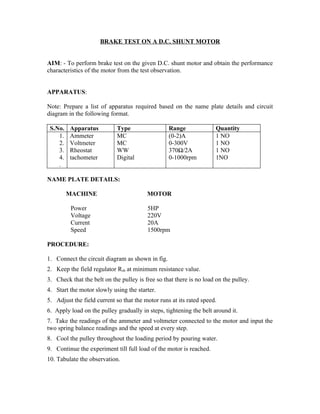
  • 1. BRAKE TEST ON A D.C. SHUNT MOTOR AIM: - To perform brake test on the given D.C. shunt motor and obtain the performance characteristics of the motor from the test observation. APPARATUS: Note: Prepare a list of apparatus required based on the name plate details and circuit diagram in the following format. S.No. Apparatus Type Range Quantity 1. Ammeter MC (0-2)A 1 NO 2. Voltmeter MC 0-300V 1 NO 3. Rheostat WW 370Ω/2A 1 NO 4. tachometer Digital 0-1000rpm 1NO . NAME PLATE DETAILS: MACHINE MOTOR Power 5HP Voltage 220V Current 20A Speed 1500rpm PROCEDURE: 1. Connect the circuit diagram as shown in fig. 2. Keep the field regulator Rsh at minimum resistance value. 3. Check that the belt on the pulley is free so that there is no load on the pulley. 4. Start the motor slowly using the starter. 5. Adjust the field current so that the motor runs at its rated speed. 6. Apply load on the pulley gradually in steps, tightening the belt around it. 7. Take the readings of the ammeter and voltmeter connected to the motor and input the two spring balance readings and the speed at every step. 8. Cool the pulley throughout the loading period by pouring water. 9. Continue the experiment till full load of the motor is reached. 10. Tabulate the observation.
  • 3. TEST READINGS : Radius of pulley R = ……..m S.No. Voltmeter Ammeter SpringBalance Speed in Reading “V” Reading “A” Readings RPM S1 Kg S2kG (N) TABULATE THE RESULTS: S.No. Current Speed Input Output B.H.P Efficiency I N VI(Watt 2IINT(Watts) Output X 100 s) 60 Input CALCULATIONS:- NOTE: Radius of Drum Pulley R Calculate for every load condition:- The torque T= 9.81 R ( S1 - S2) N-m Power output = 2IINT/60 Watts 2IINT 1 B.H.P. = X 60 735.5 GRAPHS: Plot the Graphs for BHP versus efficiency Plot the Graphs for BHP versus Torque Plot the Graphs for BHP versus current Plot the Graphs for BHP versus speed Note: All the graphs are shown in Fig,
  • 4. PRECAUTIONS: 1. Cool the pulley while the experiment is performed. 2. While measuring the radius of the pulley effective radius must be considered. RESULTS: Draw the performance characteristics for the D.C. shunt motor on a graph sheet. VIVA QUESTIONS: 1. What is the back emf of the motor? 2. Why the speed falls as load increases for a D.C. Shunt motor? 3. What are the applications of D.C. Shunt motor? 4. When is the efficiency of the motor maximum? 5. Define commutation. 6. How do you minimize reactance voltage for sparkles commutation? 7. What should be the position of rheostat in the field circuit while starting? 8. What is the nature of load connected across dc motor? 9. What will happen when dc shunt motor is started with load? 10. Give the expressions for various torques in dc motors. 11. What is the effect on speed if part of the field winding is shorted?
  • 5. BRAKE TEST ON D.C. COMPOUND MOTOR. AIM: To perform brake test on the given D.C. compound motor and determine the performance characteristics of the motor. APPARATUS : Prepare a list of apparatus based on name plate and circuit diagram in the following format. S.No. Apparatus Type Range Quantity 01 Ammeter MC 0-2A 1NO 1NO 02 Voltmeter MC 0-300V 03 Rheostat WW 370Ω/1.7A 1NO 0-20A 1NO 04 Ammeter MC NAME PLATE DETAILS: PROCEDURE: 1. Make the connections as shown in fig.5. 2. Keep the field rheostat in proper position. 3. Check that the belt is loose and the motor is not loaded. 4. Start the motor slowly with the starter. 5. Note the readings of the voltmeter and ammeter. 6. Load the motor in steps by tightening the rope around the brake drum and note the readings of the spring Balance voltmeter, ammeter and measure the speed. 7. Continue the experiment till full load is reached. 8. Slowly reduce the load and stop the motor. 9. Tabulate the observations
  • 7. TEST READINGS: Radius of Pulley:………………. S. No. S1 S2 V I N CALCULATIONS TABLE: S.No. V I N Input Output Efficiency CALCULATIONS: NOTE: Radius of Drum Pulley R. Power input = VI watt 2IINT Power out put = 9.81 x R x (S1 – S2) Watts 60 2IINT 9.81 x Rx (S1 – S2) B.H.P. = X (Metric) 60 735.5 Output (Watts) Efficiency: X 100 Input (Watts) GRAPH: Plot the graphs for BHP versus Current I Plot the graphs for BHP versus Speed N Plot the graphs for BHP versus Torque T Plot the graphs for BHP versus Efficiencyη .
  • 8. NOTE: All the graphs are shown in Fig PRECAUTIONS: 1. Keep the field rheostat in minimum resistance position while starting the motor. 2. Start the motor slowly using the starter. 3. While loading, cool the pulley by pouring cold water RESULT: Brake test on the given D.C. compound motor is performed and the performance characteristics are plotted. VIVA QUESTIONS: 1) Explain the difference between “long shunt” and “short Shunt” compounding? 2) What are the uses of different types of compound motors? 3) What is differential compounding? How is it different from cumulative compounding? 4) How do you reverse the direction of motor? 5) Draw the speed – torque curve for differential. Compound motor 6) What is flat compounding? 7) In a dc M/C, windage losses vary with speed in the proportion of ….. 8) Brake test on dc motors is usually restricted to ….HP motors 9) Why do we pour water in the brake draw during brake test? What is the effect on speed of dc compound motor if the series field winding is shorted? 10) How do you minimize iron losses in a dc machine?
  • 9. Field’s Test on dc series machine. AIM: To Determine the efficiency of the two given dc series machines which are mechanically coupled. Apparatus: Name Range Quantity DC Voltmeter 0-300V 1 No. DC Ammeter 0-20A 2 No. Tachometer 0-2000 rpm 1 No Name Plate Details: Motor Generator Power = 5.0 hp. Power = 3.0 kW Speed = 1500 rpm. Speed = 1500rpm Voltage = 230volts Voltage = 220 volts Current = 20amps Current = 13.6 amps Procedure 1. Note down the ratings of the DC Series motor and DC Series Generator. 2. Connect the circuit as shown in the circuit diagram. 3. Put a minimum load of 400 watt on the generator. 4. Switch on the DC supply and closed the DPST Switch and now vary the DC Starter till it holds with current coil. 5. Now keep the input DC Voltage constant at 220 volt DC. 6. Now increase the load of the Generator up to the rated value of armature current and take down the readings of all the meters connected in the circuit. 7. Reduce the loads one by one till the motor speed does not exceed 1800 rpm 8. Note down the readings on the instruments at different loads. 9. Gradually, reduce the armature voltage of the prime mover. Keep a minimum load of 400 watt and then switch off the supply
  • 11. TABULATIONS: Observations : Armature resistance of the motor Ral = 2.0 ohms. Series field resistance of the motor Rsel = 0.8 ohms. Armature resistance of the generator Ra2 = 2.0 ohms Series field resistance of the generator R se2 = 0.8 ohms. CALCULATIONS: V1 = I1 = VL = IL = Power Input Pin = V1 I1 Power output P out = VL IL Total losses in two machines PL = Pin – P out Field copper losses in the motor =P1= I1 2 Rsel Field copper losses in the generator = P2=I12 Rse2 Armature copper losses in the motor =P3= I12 x Ral Armature copper losses in the generator = P4=IL2 x Ra2 Total cu losses in the field and armature of generator and motor is P cu Pcu = P1+P2+P3+P4 watts PL – Pcu Stray losses in each machine Ws = = 2 Motor Efficiency Calculations: Power input to the motor Pin = V1 I1 2 Rse2 Total losses in the motor W ml = I12 Rsel + I12 + Ws Motor Output Pout= Pin – Wml
  • 12. Pout % Efficiency = x 100 = x 100 P in Generator Efficiency Calculations: Generator output Pout (g) = VL IL Total losses in the Generator Wgl = Ws + Il 2 Rse2 + IL2 Ra2 Power input to the generator Pin = Pout (g) + Wgl Pout % Efficiency of the generator = x 100 Pin
  • 13. HOPKINSON TEST AIM: To perform Hopkinson test on the given motor generator set and determine the efficiency of both motor and generator. APPARATUS: S.No. Apparatus Type Range Quantity 01 Ammeter 02 Voltmeter 03 Rheostat NAME PLATE DETAILES: PROCEDURE: 1. Make the connection as shown in fig 2. Keep the rheostat in motor field at minimum and generator field at maximum resistance position And the switch K open. 3. Start the motor generator set slowly with motor starter and adjust the field to rated value by field rheostat of the motor. 4. Excite the generator by decreasing the generator field rheostat resistance 5. If the voltmeter Vs reads zero then close the paralleling switch K 6. Load the generator in steps by decreasing the field rheostat resistance of the generator or by increasing the field rheostat resistance of the motor. 7. Take the readings of all the meters for each load and measure the speed in each step. 8. Reduce the excitation of the generator by increasing the field rheostat of the generator and open the Switch K. 9. Switch the supply to motor-generator switch. 10. Tabulate the observations.
  • 14. TEST READINGS: S.NO I1 I2 I3 I4 V VS VG N S.No. Motor Motor Motor Generator Generator Generator Input Output Efficiency Input Output Efficiency MODEL CALCULATIONS: Input power to motor = V l1 Watts = Total excitation and Stray losses Generator set = Total excitation and stray losses Vl 1 Stray losses of each machine = Watts. Z Efficiency of motor : Motor input Power = V (l1 + l2) Output power = input power-Motor armature copper loss – Motor shunt field loss- Stray loss Ws = V (l1 + l2) – (l1 + l2-l 3)2 Ram – Vl3 - Watts 2 Output % Efficiency = x 100 Input Efficiency of generator Generator output power = VI2 Watts Input Power = Output + Gen. Armature copper loss + Generator Shunt field loss + stray loss Ws = VI2 + (l2 + l4)2 Rag + Vl4 + 2 Output % Efficiency = X 100 Input
  • 15. 8. GRAPHS: Plot the output versus efficiency curves for both the motor and the generator as shown in the figure . PRECAUTIONS: 1) Keep the rheostats in motor and generator field circuit at proper positions while starting the motor. 2) Excessive care while closing the parallel switch K. The voltmeter must read zero for K to be closed. RESULT: Hopkinson test on the given D.C. Machine is performed and the performance characteristics are plotted. VIVA QUESTIONS: 1). what are the advantages of the test? 2) Can this test be applied to compound machines? Explain 3) When two D.C. machine s are paralleled as is done in this test, which machine acts as generator and which machine acts as motor? 4). what are the disadvantages of this test? 5) What are heat run tests? 6) Hopkinson’s test is a ………..test. 7). Hopkinson’s test on D.C. Machines is conducted at ….load. 8). The armature voltage control of D.C. motor provides …… drive.
  • 16.
  • 17. MAGNETIZATION CHARACTERISTIC OF A D.C. SHUNT GENERATOR. AIM: To determine experimentally the magnetization or open circuit characteristic of a generator and determine the critical field resistance and critical speed APPARATUS: Prepare a List of the apparatus required based on the name plate ratings and Circuit diagram in the following format. S. No. Apparatus Type Range Quantity 1. Rheostats 2. Voltmeters 3. Ammeters 4. Tachometers 5. Knife switch NAME PLATE DETAILS: Specifications Motor Generator Rating Field current Load current Voltage PROCEDURE: 1. Connect the circuit as shown in the fig 2. Set the potential divider to zero output keeping motor field rheostat in minimum resistance position 3. Switch on the supply and start the motor with the help of the starter. Adjust the speed of the motor generator set to the rated speed of the generator by controlling the motor field resistance the set speed is to be maintained constant throughout the experiment Note down the voltmeter reading at zero field current (lf). Increase the field current lf uniformly in steps, by changing the potential divider tapping, simultaneously note down the field current (lf) and the terminal voltage (E) across the generator armature terminals. 4. Continue the experiment till saturation of the field is reached. 5. Continue the experiment for decreasing values of If in steps by decreasing the tapping of potential divider.
  • 19. TEST READINGS: Increasing lf Decreasing If S.No. lf E S.No. Lf E Critical Field Resistance: It is that value of the field resistance at which the D.C. shunt generator will fail to excite. Critical Speed: It is that speed for which the given shunt field resistance becomes the critical field resistance. Critical field resistance is obtained by plotting the OCC as in fig.2 and determining the slope of the tangent to the linear position of the curve from the origin. While drawing the tangent, the initial position of the O.C.C is neglected. OX is the tangent Critical Field resistance Rc = BC AB OY is the shunt Field resistance line The Critical speed Nc = YZ x Rated Speed. XZ Rated speed is the speed at which the OCC is obtained. PRECAUTIONS:
  • 20. 1. Perform the experiment at constant speed. 2. Readings are to be taken for uniformly increasing and then uniformly decreasing field current. 3. Check must be made for residual magnetism otherwise; the field terminals may be required to be reversed. RESULT: Magnetization characteristics are observed. VIVA QUESTIONS: 1. Why is the magnetization characteristic different for increasing and decreasing of values of lf? 2. What is the purpose of starter for the motor? 3. Why is the speed maintained constant during the experiment? 4. Why is the motor field resistance kept to a minimum while starting the motor? 5. What is residual magnetism? 6. Define critical resistance. 7. Define critical speed. 8. How do you determine critical resistance with help of O.C.C.? 9. Explain magnetization curve. 10. How do you determine critical speed graphically? 11. Define coercive force 12 Explain hysteresis phenomenon.
  • 21. SEPARATION OF LOSSES IN A D.C. SHUNT MACHINE AIM: To perform suitable tests on the given D.C. shunt machine and determine from the experiment the stray losses and separates these into friction, hysterics and eddy current losses. APPARATUS: Prepare a list of apparatus based on name plate and circuit diagram in the following format. S.No. Apparatus Type Range Quantity 01 Ammeter MC 0-2A 2NO MC 0-300V 1NO 02 Voltmeter 03 Rheostat WW 370Ω/1.7A 2NO 04 tachometer digital 0-2000rpm 1NO NAME PLATE DETAIS: PROCEDURE: 1). Make the connections as per the circuit diagram as shown in FIG. 2). Start the motor slowly using starter keeping the field and armature rheostats in Minimum and maximum position respectively. 3) Adjust the field current to the rated value at no- load 4) Reduce the armature circuit resistance in steps, increasing the speed. 5) Take the readings of voltmeter, ammeter and speed at constant field current. 6) Continue the experiment till maximum speed is obtained by cutting out the complete resistance in armature circuit (Do not exceed rated speed) 7) Bring the armature rheostat back to full resistance (initial) position. 8). Repeat the experiment with a reduced field current. (75% rated excitation) stop the motor.
  • 22. 9) Stop the motor 10) Measure the armature resistance by voltmeter-ammeter method using the circuit diagram as shown in Fig. 11). Tabulate the readings. TEST READINGS : Field Current (lf1) A S.No. N V lf la Field Current (lf2) A S.No. N V lf la CALCULATIONS: IF1…………….A IF2……………………A S.No. V-la Ra= W=Ea W S.No. V-la Ra= W=Ea la W Eb la N Eb N CIRCUIT DIAGRAM:
  • 23. GRAPH: Plot W/N Versus N for both the field excitations: From the graph find out
  • 24. B1 + D= bc/ab B + D = ef/de Determine A+C and A1 + C Solve for A, A1, B, B1, C, D. RESULT : At rated speed the various losses are results Hysteresis loss = ………………W Eddy Current loss = ……………… W Friction loss = …………………… W Wind age loss = ……………….. W PRECAUTIONS: 1. Keep the field current constant during each part of the experiment. 2. Check the position of the rheostat positions before stating the motor. VIVA QUESTIONS: 1). How Hysteresis losses occur in a D.C. Machine? 2) Where are eddy current losses occurring in a D.C. Machines? 3) How are the magnetic losses minimized? 4) How is brush contact resistance loss taken into consideration in practice? 5) Give the expression for hysteresis loss. 6) What is the effect of armature reaction? 7) How do you minimize cross magnetizing effect of armature reaction. 8) Differentiate MNA & GNA 9) Which test gives us stray losses? SWINBURNE’S TEST AIM: To perform Swinburne’s test on the given D.C. machine and predetermine it efficiency at any desired load both as motor and as generator.
  • 25. ARATUS REQUIRED: Prepare a list of apparatus based on name plate and circuit diagram in the following format. S. No. Apparatus Type Range Quantity 01 Ammeter MC 0-2A 2NO 02 Voltmeter MC 0-300V 1NO 03 Rheostat WW 370Ω/1.7A 1NO 04 Ammeter MC 0-20A 1NO 05 Tachometer digital 0-10000rpm 1NO NAME PLATE DETAILS: Voltage : Field Current:………………… Load Current:………………………. Speed:……………………… PROCEDURE: 1) Make the connections as in fig 2) Start the D.C. motor with the starter slowly and bring it to rated speed. 3) Take the no load readings of input current, armature current, field current and input voltage. 4) Stop the machine. 5). Measure the armature resistance using circuit diagram as shown in Fig. 6). Measure the field resistance using the circuit diagram as shown in Fig .by replacing the armature by shunt field winding Tabular columns:
  • 26. Measurement of Ra Measurement of Rsh S.No. Va Ia Va S.No. Vsh Ish Vsh Ra = Rsh = La lsh Average Ra (t1) = ……………….. Ω Average Rsh (t1) = ……………….Ω S.NO V(volts) IL(AMPS) If(amps) N(rpm) MODEL CALCULATIONS:
  • 28. PRECAUTIONS: 1 Keep the field rheostat at the minimum resistance position and armature rheostat in maximum resistance position while starting the motor. 2. The experiment is to be performed only at no-load. 3. After starting the motor the armature rheostat must be fully cut- off. RESULT: Efficiency at no load condition calculated and performance curves drawn. VIVA QUESTIONS 1. What are the advantages of the Swinburne test? 2. Why Swinburne test cannot be performed on series machines? Explain. 3. How do you obtain accurate measurements in this experiment? 4. How do you reverse the direction of motor? 5. Draw the speed – torque for diff. Compound motor. 6. What is Flat Compounding? 7 Ia a dc m/c, winding losses varies with speed in the proportion of ----------- 8. Brake test on D.C. Motors are usually restricted to ---------- HP motors. 9. Why do we pour water in the brake drum during brake test? 10. What is the effect on speed of d.c. compound for if the series field winding is shorted. 11. How do you minimize iron losses in a dc machine? SPEED CONTROL OF D.C. SHUNT MOTOR
  • 29. AIM: To determine the speed characteristics of D.C shunt motor by (i) field control and (ii) armature control: APPARATUS REQUIRED: Note: Prepare a list of apparatus required based on name plate ratings and circuit diagram in the following Format. S.No. Apparatus Type Range Quantity 01 Ammeter MC (0-2)A 1NO 02 Voltmeters MC (0-300)V 1NO 03 Rheostat WW 370Ω/1.7A 2NO 04 Tachometer Digital 0-10000rpm 1NO NAME PLATE DETAILS: Rating ……………………………………. Load Current ……………………….. Voltage ………………………………….. Speed ………………………………... PROCEDURE: 1. Make connections as per the circuit diagram fig. 2. Keep the field rheostat in the minimum resistance position and the armature resistance in the maximum resistance position. 3. Start the motor by closing the switch and operating the starter slowly. 4. For the field control method, adjust the rheostat R2 so the voltmeter reads about 200 volts. 5. Increase the field resistance in steps there by decreasing the field current. Note down the values of lsh, the shunt field current and the speed. Take enough readings (8 to 10) to obtain a good curve. 6. For armature control, keep the field rheostat at a selected field current value note the rated field current? 7. Decrease the armature resistance from maximum position in steps keeping the field current at the set value. Note down the speed for each value of armature voltage.
  • 31. Field control (Va=……) Armature Control (lf=…………..) S.NO. Ish N S.No. Va N GRAPH: Plot Ish Vs N and VA (armature voltage) α N graphs. PRECAUTIONS: 1. Keep the armature and field rheostats at proper positions while starting the motor. 2. Maintain constant field current for armature control and constant armature voltage for field control part of the experiment. RESULT: The variation of speed with armature voltage and field current in case of D.C. shunt motor is studied. VIVA QUESTIONS: 1. What will happen if the shunt field is open during running? 2. What is the purpose of No volt coil in a D.C. Motor? 3. How do you change the direction of rotation of a D.C. Shunt motor? 4. What are the methods of speed control in a dc shunt motor? 5. In which method of speed control, above the base speed can be achieved, why? 6. List the merits and demerits of armature voltage control method. 7. What is the necessity of starter? 8. What is the function of OLR coil in dc starter? 9. What is the advantage of 4- point starter over 3-point starter? 10. Which is the precise method of speed control of dc motors?
  • 32. LOAD TEST ON D.C. SERIES GENERATOR AIM: To perform load test on a D.C. series generator and to draw the internal and external characteristics. APPARATUS: Note: Prepare a list of apparatus required based on name plate ratings and circuit diagram in the following format. S.No. APPARATUS TYPE RAANGE QUANTITY 1. Rheostats WW 370Ω/1.7A 1NO 0-300V 1NO 2. Voltmeters MC 3. Ammeters MC (0-20)A 1NO 4. Tachometers Digital 0-10000rpm 1NO NAME PLATE DETAILS: Parameter Motor Generator Rating Load current Field current Speed PROCEDURE 1). Connect the circuit as shown in fig. 2) Keep the motor field rheostat in minimum resistance position and do not connect any load on the generator 3) Switch on the supply and start the motor with the help of starter. 4). Adjust the speed by controlling the motor field resistance. 5) Now, switch ON the load and for different values of load, note the ammeter and voltmeter readings. 6). after loading the generator up to the rated value gradually reduce the load in steps and switch off the supply.
  • 33. CIRCUIT DIAGRAM :- STARTER L A Z + - 0- 30A Y YY + A - 220 v, A Load Z Rheostat D.C M A supply + G V AA - ZZ AA -- Fig. 10.1 : Load test on d.c. Series generator TEST READINGS :
  • 34. S.NO IL(AMPS) V(VOLTS) Eg(VOLTS) Model calculations: V= Eg – la (Ra + Rse) Where V = Terminal voltage Eg = Emf generated in the armature (Volts) La = Armature current (A) = lse = lL Ra = Armature resistance (Ω) Rse = Series field resistance (Ω) PRECAUTIONS: 1). Loose connections are to be avoided. 2). Remove the load gradually in steps and switch OFF the motor RESULT: Performance characteristics are observed. VIVA QUESTIONS.
  • 35. 1) How the internal characteristics are derived from external characteristics? 2) What are reasons for the failure of a D.C. series generator to build up voltage? 3) What is meant by critical resistance of a D.C. series generator? 4) What is the necessity of starter in D.C. Motors? 5) What material used for brushes, why? 6) Why are external characteristic lies below the internal characteristic in D.C. Shunt generators? 7) What is the critical load resistance? 8) How do you control the speed of D.C. Motor? LOAD TEST ON D.C. SHUNT GENERATOR
  • 36. AIM: To perform load test on D.C. Shunt Generator and determine there from the internal and external characteristics of the generator. APPARATUS: Prepare a list of apparatus based on name plate and circuit diagram in the following format. S.No. Apparatus Type Range Quality 01 Ammeters MC (0-2)A 1NO 02 Voltmeters MC 0-300V 1NO 03 Rheostats WW 370/1.7A 2NO 04 Tachometer Digital 0-10000rpm 1NO NAME PLATE RATINGS:- Motor Generator Power 5HP Power 3KW Voltage 220V Voltage 220V Current 20A Current 13.6A Speed 1500rpm Speed 1500rpm PROCEDURE: 1) Make the connection as shown in the circuit diagram as shown in the fig Start the motor with the help of the starter. 2) Adjust the field regulator of the motor so that the generator runs at its rated speed. 3) Adjust the generator field regulator so that rated voltage is obtained at its terminals. 4) Gradually apply the load in steps and note down the readings of the load as given on the name plate of the generator. Keep the speed constant at its rated value by adjusting motor field regulator throughout experiment. 5) Plot the external load characteristic from the observations. 6) Determine the armature resistance experimentally using the circuit diagram in fig. 7) Take at least 6 readings of voltmeter and armature by varying the load resistance and determine the average value of the armature resistance.
  • 37. OBSERVATION TABLE: Speed ………R.P.M. S. No. Load Current Terminal Voltage Field Current IL V If CALCULATIONS: Average value of armature resistance Ra = ----------Ω S.NO. l a = l L + LF E = V + La Ra GRAPHS : 1). Plot the external or load characteristic from the table.1 (lL Vs V curve ) 2) Plot the internal characteristic or total characteristic from Table No.2 (la Vs E Curve)
  • 38. PRECAUTIONS: 1) While starting the motor, field regulator (rheostat) must be in minimum position 2) While loading the generator, at every step speed of the generator must be maintained. At rated value by adjusting the motor field regulator. 3). Decrease the speed before removing the load after the experiment is completed at full load. 4) Do not over load the generator RESULTS: Internal and external characteristics are plotted by conducting load test on the given D.C. Shut generator. VIVA QUESTIONS: 1) If the shunt generator fails to buildup what could be the reason for it. Explain how this can be over come 2) What is meant by armature reaction? 3) Why are the characteristics of the shunt generator drooping? 4) DC Generators are normally designed for max efficiency around ….load 5) What will happen when R-C load is connected across armature? 6) For a properly designed dc generators the over all efficiency could be of the order of -----% 7) Define commercial & electrical efficiencies for dc generators 8) Which losses in a dc generator vary significantly with the load current? 9) Draw the internal and external characteristics for a dc shunt generator.
  • 39. CIRCUIT DIAGRAM: LOAD TEST ON DC COMPOUND GENERATOR.
  • 40. AIM: To conduct a load test on given DC compound generator and to plot the internal and external characteristics of the generator. APPARATUS REQUIRED: S.No Apparatus Type Range Quantity 01 Ammeter MC 0-2A 1NO 1NO 02 Voltmeter MC 0-300V 03 Rheostat WW 370Ω/1.7A 2NO 04 Ammeter MC 0-20A 1NO 05 Tachometer digital 0-10000rpm 1NO NAME PLATE DETAILS: Parameter Motor Generator Rating 5HP 3KW voltage 220V 220V Load current 20A 13.6A Speed 1500RPM 1500RPM PROCEDURE: Connect the circuit as per the circuit diagram shown in fig 1. Keep the field regulator of the motor in the minimum resistance position and regulator of the generator in the maximum resistance position. 2. Switch on the supply and start the motor with the help of its starter. 3. Adjust the field regulator of the motor such that it runs its rated speed given on the name plate. 4. Adjust the armature regulator of the generator to build up its rated voltage given on its name plates on no load. 5. Note down the no loads of ammeter and volt meter in tabular form. 6. Increase the load gradually in steps and tabulate the readings 7. Plot the external characteristics is load current Vs terminal voltage. 8 Connect the generator for differentially compounding, repeat the process and plot the external characteristics.
  • 41. CIRCUIT DIAGRAM: OBSERVATIONS: S.NO V(volts) IL(AMPS) If(AMPS) Ia=IL+If Eg=V+Ia(Ra+Rf)
  • 42. GRAPHS:- 1). Plot the external or load characteristics from table 1. (IL Vs V curve) 2). Plot the internal characteristics or total characteristics from table 2. (lL Vs Eb curve ) PRECAUTIONS: 1).Loose connections must be avoided. 2) The generator must be seen at constant speed through out the experiment. 3) The position of the starter must be checked before giving supply 4) The resistance of the field regulator of the motor must be adjusted to minimum resistance position at the time of switching on the supply. 5).the resistance of the field regulator of the generator must be adjusted maximum resistance at the beginning. RESULTS: Internal and external characteristics are plotted by conducting load test on the given DC compound generator. VIVA QUESTIONS:- 1). How many field windings are there in a compound generator? What are they?
  • 43. 2). what does compounding mean? 3). Draw the external characteristics for a level compound generator 4). in a compound wound generator which of the two fields dominate 5) Discuss the performance of a DC compound generator using only one field winding at a time. 6). what is meant by commutation? 7) What are the different methods oaf obtaining spark less or good commutation? 8) Why do you perform load test? 9) Differentiate cumulative & differential compound generators. 10). Give at least three applications of dc compound generators. 11) What is the critical resistance’s in a dc shunt machine?