Testo - Stationary Measurement - Humidity and Temperature
•
1 gefällt mir•1,097 views

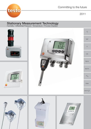
Stationary Measurement Technology - Humidity / Differential Pressure / Temperature / Process Displays

Empfohlen
Weitere ähnliche Inhalte
Was ist angesagt?
Was ist angesagt? (20)
Ähnlich wie Testo - Stationary Measurement - Humidity and Temperature
Ähnlich wie Testo - Stationary Measurement - Humidity and Temperature (20)
Mehr von Testo Limited
Mehr von Testo Limited (20)
Kürzlich hochgeladen
Kürzlich hochgeladen (20)
Testo - Stationary Measurement - Humidity and Temperature
- 1. Committing to the future 2011 Stationary Measurement Technology Humidity / Differential Pressure / Temperature / Process Displays °C %rF V mA Nm/s Nm3/h °Ctd mbar inch H2O
- 2. Contents A Humidity transmitters testo 6621, testo 6631, testo 6651, testo 6681 6 A1 Overview measurement transmitter versions and applications testo 6621, testo 6651, testo 6681 6 A2 Air conditioning humidity transmitter testo 6621 9 1 Description 9 2 Application 9 3 Technical data 10 4 Electrical connection 11 4.1 Wiring 11 4.1.1 Wiring 4-wire 11 4.1.2 Wiring 2-wire 11 4.1.3 Wiring 3-wire technology 11 5 Technical drawings 12 5.1 Installation A01 wall version 12 5.2 Installation A02 duct version 13 5.3 Installation A03 wall version 14 6 Installation 15 6.1 Installation A01 wall version 15 6.2 Installation A02 duct version 15 6.3 Humidity sensor exchange 17 7 Specifications 17 A3 Stable ambient conditions in greenhouses testo 6631 18 1 Description 18 2 Electrical connections 18 3 Technical drawings 19 A4 Humidity transmitter testo 6651 20 1 Description 20 2 Exchangeable probes, probe series testo 6600 20 2.1 Description of probe series 20 3 Technical data 21 3.1 testo 6651 21 3.2 Probe series testo 6600 22 A5 Humidity transmitter testo 6681 23 1 Description 23 2 Exchangeable probes, probe series testo 6610 23 2.1 Description of probe series 23 3 Technical data 24 3.1 testo 6681 24 3.2 Probe series testo 6610 25 A6 General information on the transmitters testo 6651 and testo 6681 26 1 Operating menu 27 2 Self-monitoring / Status: generated reports 28 3 Wiring / electrical connection 29 4 Technical drawings 32 5 Installation 33 5.1 Wall version 33 5.2 Duct version 33 6 Specifications 34 6.1 testo 6651 and probe series testo 6600 34 6.2 testo 6681 and probe series testo 6610 35 2 Further information at www.testo.com
- 3. Contents B General information on all Testo humidity transmitters 36 1 P2A software for parameterization, analysis and adjustment (testo 6621, testo 6651 and testo 6681) 36 1.1 Overview P2A software 36 1.2 Operation 36 1.3 Operating menu (in the P2A software) 37 1.4 Carrying out adjustments via the P2A software 38 2 Protective caps 39 3 Adjustment/calibration and calibration certificates 41 3.1 Adjustment / calibration for testo 6621, testo 6651 and testo 6681 41 3.1.1 1-point adjustment 42 3.1.2 2- point adjustment 42 3.2 Calibration certificates 43 3.2.1 Certificates 43 3.2.2 Temperature calibration certificates 44 3.2.3 Humidity calibrations 44 4 Sensor 45 4.1 Capacitive Testo humidity sensor 45 4.2 Functionality of the 650 HP and testo 6681 with probe testo 6614 (heated sensor for high humidity applications) 46 4.3 Temperature sensor (NTC = Negative Temperature Coefficient) 47 4.4 Temperature sensor (Pt 1000 Class A9) 47 5 Physical principles 47 5.1 Water vapour partial pressure 47 5.2 Saturated vapour pressure 49 5.3 Relative humidity 50 5.4 Dewpoint temperature 50 5.5 Absolute humidity [g/m³]) 50 5.6 Degree of humidity X or mix ratio 50 5.7 Wet bulb temperature 50 5.8 Psychrometric chart for air conditioning applications 51 5.9 Temperature and pressure-dependency of humidity parameters 52 Further information at www.testo.com 3
- 4. Contents C Differential pressure transmitters 54 C1 Overview of versions and applications 54 C2 Differential pressure transmitter in cleanroom-conform panel design testo 6388 (10 Pa to 10 hPa) 56 1 Description 56 2 Technical data 57 3 Connection plan 58 4 Technical drawings 58 C3 Differential pressure transmitter with temperature / humidity option testo 6381 (10 Pa to 1000 hPa) 60 1 Description 60 2 Technical data 61 3 General technical data / Connection plan 62 4 Technical drawings 62 C4 Differential pressure transmitter with high long-term stability and accuracy testo 6351 (50 Pa to 2000 hPa) 64 1 Description 64 2 Technical data 65 3 Connection plan 66 4 Technical drawings 66 C5 Differential pressure transmitter for building climate testo 6321 (100 Pa to 2000 hPa) 68 1 Description 68 2 Technical data 69 C6 Adjustment of zero-point / Calibration certificates 70 1 Adjustment of zero-point / Calibration certificates 70 1.1 Calibration certificates 70 2 Physical principles 71 2.1 Definition of pressure 71 2.2 Overview of pressures 71 2.3 Atmospheric air pressure (Patm) 72 2.4 Absolute pressure (Pabs) 72 2.5 Differential pressure (AP) 72 2.6 Relative pressure (Prel) 72 2.7 Signal delay/damping 73 D Temperature transmitter 74 1 Description 74 2 Technicaldata 75 3 Connection plan 76 4 Technical drawings 76 4 Further information at www.testo.com
- 5. Contents E testo 54 Process displays / external displays 78 1 Description 78 2 Ordering options 78 3 testo 54-3 with relay outputs 79 3.1 Electrical connections for testo 54-3 79 4 Temperature/analog value process displays (external displays) testo 54-7/-8 with relay outputs and RS485 output and min./max. value store 80 4.1 Electrical connections for testo 54-7/-8 80 5 Accessories for process display testo 54 81 6 Technical drawings 82 6.1 Technical drawing testo 54-3/-7/-8 82 6.2 Technical drawings wall housing 83 6.3 Technical drawings alarm column 84 7 Process display 54 - the basics 85 7.1 Limit value settings 85 7.1.1 Difference between relay output and switch output 85 7.1.2 Relay outputs can be set as opener or closer 85 7.1.3 Limit value settings (AUTO or LATCH signal) in testo 54-3/-7/-8 86 7.2 Keylock "Key" in testo 54-3/-7/-8 87 7.3 Using the auxilliary energy output 87 7.4 MIN./MAX. value store 88 7.5 Totaliser 88 7.5.1 Totaliser function 88 F Information relevant for all measurement transmitters 89 1 Avoiding errors in wiring 89 1.1 2-wire technology (4 to 20 mA) 89 1.2 4-wire technology (0 to 20 mA, 4 to 20 mA, 0 to 1 V, 0 to 10 V) 90 1.3 Wiring guide 91 2 Selection assistance for voltage supply 93 2.1 Description of the voltage supply possibilities 93 2.2 Dimensional drawing of voltage supplies 94 2.2.1 Desktop mains unit (0554.1748) 94 2.2.2 Top hat rail mains unit (0554.1749) 95 3 Calibration and adjustment 96 4 Influence of the measurement inaccuracy of the reference instrument 96 5 Scaling and resolution 97 6 Housing protection according to IP (International Protection) 98 6.1 Tightness according to IP-norm 98 6.2 Watertightness test at Testo (based on DIN VDE 0470-1/ EN 60529 / ICE 529) 99 Further information at www.testo.com 5
- 6. A Humidity transmitters testo 6621, testo 6631, testo 6651, testo 6681 A1 Overview versions and applications humidity transmitters testo 6621, testo 6651, testo 6681 Testo offers three classes of new transmitters for humidity Both instrument series present many innovations, including world measurement. The following is a rough presentation of the three firsts such as a Profibus interface in the humidity transmitter testo classes. After this, each class is described in detail. 6681 and an Ethernet interface in the humidity transmitters testo The price and performance of the testo 6621 make it ideal for air 6681 and testo 6651. conditioning applications in buildings. The models testo 6651 and It is a completely newly developed generation of instruments, which in testo 6681, are positioned in the middle to upper performance range. particular offers solutions for safe and service-friendly use, meaning They are designed for the monitoring of critical climate in process high reliability and operational security for industry: engineering and also in compressed air technology. The demanding measurement is realized with the further developed Testo humidity – exchangeable probes sensor, with its well-known and highly-valued long-term stability. Unmatched state-of-the-art technology in humidity measurement, – early warning reports with solutions for highest accuracy as well as for special applications (high humidity, humidity in H2O2, trace humidity etc.) is provided. – variable possibilites for adjustment In addition, they also continue to use already existing technology such as the external interface for communication, for example for the parameterization and adjustment software P2A from Testo. Process requirement Ethernet Ethernet testo 6681 testo 6651 testo 6621 Air conditioning technology: Air conditioning technology and Industry: Application in rooms or air industry: Critical ambient conditions, cleanrooms, drying conditioning ducts Critical ambient conditions, processes, high humidity, trace humidity, cleanrooms humidity in H2O2 environments etc. Application area 6 Further information at www.testo.com
- 7. A1 Overview versions and applications humidity transmitters testo 6621, testo 6651, testo 6681 Product selection by instrument testo 6621 testo 6651 testo 6681 Measuring range Humidity 0 to 100 %RH 0 to 100 %RH 0 to 100 %RH (no high humidity processes) (no high humidity processes) Temperature 0-20 to +120 °C , -20 to +120 °C (-4 ... +248 °F) -40 to +180 °C (-40 ... +356 °F) (dependent on (not for high humidity processes), probe) duct: -20 to +70 °C (-4 to +158 °F) Accuracy at Humidity** ±2.0 %RH (0 to 90 %RH) ± (1.7 + 0.007* Mw) %RH (0 to 90%RH) up to ± (1.0 + 0.007* Mw) %RH (0 to 90%RH) +25 °C (+77 °F) ±4 %RH (90 to 100 %RH) ± (1.9+ 0.007* Mw) %RH (90 to 100%RH) ± (1.4+ 0.007* Mw) %RH (90 to 100%RH), dependent on probe Temperature ±0.5 °C / 0.9 °F Pt1000 Klasse A: ±0,2 °C / 0,38 °F * Pt1000 1/3 Class B / Pt 100 1/3 Class B Pt1000 1/3 Klasse B: ±0,15 °C / 0,27 °F * (testo 6605) for testo 6615 ±0.15 °C / 0.27 °F * Measurement parameters °C, °F, %RH °C/°F, %rF/%RH, °Ctd/°Ftd °C/°F, %rF, %RH, °Ctd, °Ftd, g/m3, gr/ft3, g/kg, gr/lb, enthalpy, °Ctw, °Ftw, inch H2O, ppm(vol), % Vol for H2O2-applications: °Ctm/°Ftm Signal outputs 4 to 20 mA, 2-wire (duct version only) 4 to 20 mA, 2-wire 4 to 20 mA, 2-wire (not for testo 6614/6615) 0 to 1 Volt, 4-wire 0/4 to 20 mA, 4-wire 0/4 to 20 mA, 4-wire 0 to 5/10 Volt, 4-wire 0 to 1/5/10 Volt, 4-wire 0 to 1/5/10 Volt, 4-wire Mounting variants Wall or duct installation Wall probe testo 6601 Wall probe testo 6611 Duct probe testo 6602/6603 Duct probe testo 6612 Cable probe testo 6604/6605 Cable probe testo 6613/6614/6615/6617 max. cable length – 5m 10 m Housing ABS and nickel-plated ABS ABS, plastic, IP65 Metal, IP65 Interfaces digital Testo (for 2PA software or digital Testo (for P2A software or testo digital Testo (cf. testo 6651) 400/650) Profibus (optional intermediary layer) testo 400/650) Ethernet(optional intermediary layer) Ethernet (optional intermediary layer) Special features External interface, adjustability 4 relays (optional) Special probe versions for early warning system (via display or • Temperature ranges up to +180 °C (+324 °F) relay collective alarm) • Trace humidity testo 6615 • High humidity testo 6614 • Self-diagnosis testo 6617 4 relays, optional early warning system (via display, relay collective alarm or Profibus) *Other accuracies apply for the wall probe with 70 mm length in combination with a current output (P07): Operation: with 2 channels at 12 mA, without display illumination, relay off, additional measurement inaccuracy to above data at +25 °C (+77 °F), humidity ±2.5 %RH, temperature ±1 °C (1.8 °F) **For more detailed explanation on the determination of the measurement uncertainty according to GUM, see p. 20/25 Product selection by probe (only testo 6651 / testo 6681 with exchangeable probes) Wall Duct Cable Standard For Security For trace –> auto- ±1 %RH ±1.7 %RH ±1 %RH ±1.7 %RH ±1 %RH ±1.7 %RH high humidity diagnosis humidity –> with at the –> heated auto- sensor adjust -20 to +70 °C -20 to +70 °C -30 ... +120 °C -40 ... +180 °C -20 to +70 °C -30 ... +120 °C (-4 to +158 °F) (-4 to +158 °F) (-4 to +248 °F) (-40 ... +356 °F) (-4 to +158 °F) (-4 to +248 °F) ±1.7 %RH ±1.7 %RH -60 to +30 °Ctd 6601 6602 6603 6604 6605 (-76 to +86 °Ftd) Probes for testo 6651 (testo 6600) -40 to +180 °C -40 to +180 °C -20 to +70 °C -40 to +180 °C (-40 to +356 °F) (-40 to +356 °F) (-4 to +158 °F) (-40 to +356 °F) 6611 6612/6622 6613/6623 6614 6615 6617 Probes for testo 6681 (testo 6610) Further information at www.testo.com 7
- 8. A1 Humidity transmitters testo 6621, testo 6651, testo 6681 An exact and continuous measurement of temperature and humidity is Depending on the model, the Testo humidity transmitters fulfil the strict, or vital in many industrial processes. strictest, demands placed on humidity measurement accuracy and long- term stability. The most important areas of application for the testo 6651/6681 are The following table helps with the allocation of the transmitter models to • continuous monitoring or regulation of climate the applications. (Note: The following table only provides general (e.g. production air quality or storage) information - please adapt the selected model and ordering options to the demands of the process yourself. Testo’s Sales Department will be happy • Drying processes / high humidity processes, to assist you with your selection): • Humidity measurements in H2O2 atmospheres Air conditioning applications Application Recommendation Alternative Semi-conductors (cleanroom) in air ducts testo 6681 with 6612 / 6613 testo 6651 with 6602 / 66109 Pharmaceuticals (cleanroom) in air ducts testo 6681 with 6612 / 6613 testo 6651 with 6602 / 6603 Paintshops testo 6681 with 6612 / 6613 and PTFE protective cap testo 6651 with 6602 / 6603 with PTFE protective cap Storage of hygroscopic materials testo 6651 v 6611/ 6613 or testo 6681 with 6611 / 6613 testo 6651 with 6602 or testo 6681 with 6612 Storage of electronic componenets testo 6681 v 6613 testo 6651 with 6601 / 6603 Production air quality testo 6651 v 6611 testo 6681 with 6611 Silencer Dehum- Venti - Measurement point Humidity transmitter in input air Hygrotest in input air: Nom./act. comparison B B idifier lator Filter A A only required for In air conditioning systems, % RH/ T % RH/ T / circulating air of humidity -> there are three potential control Outside air measurement points for the Air input transmitters outside air- M conditioned rooms. First Humidifier T - the condition of the outside T + air A is recorded, after Cooling Heating Mixing chamber with filtration, cooling/heating flaps and regulating and, where necessary Input air motor (regulated Air-conditioned conditioning humidifying/dehumidifying, room dependent on the condition of the input %RH / T air is recorded B . The Circulating A und C ) air C third measurement point is Silencer Venti - % RH/ T in the circulating air C . The lator data from B serve to control the input air Exhaust air conditioning; the data Air output from A and C , on the other hand, decide the © = Typical installation sites for hygrotest: DHT if hygrotest directly in duct position of the flaps in the PHT if hygrotest dislocated from measurement site mixing chamber (mixture of WHT inside air-conditioned rooms/zones outside and circulating air). For installation in rooms: Do not install WHT close to ventilation outlets or on badly isolated outside walls Drying processes / high humidity processes For high humidity applications note: A high humidity application is when the humidity > 90%RH for longer periods! For high humidity applications with constant temperatures, the testo 6681 with 6613 with a PTFE protective cap + condensation protection is used. For high humidity applications with changing temperatures, the use of the PTFE protective cap with condensate drip hole (0554 9913) and condensation protection (0554.0166) is recommended. Application Recommendation Alternative Climate cabinets testo 6681 with 6613 Maturing cheese testo 6681 with 6613 / 6614 incl. PTFE protective cap with drip hole and condensation protection Drying pasta testo 6651 with 6612 or testo 6681 with 6612 Drying tobacco testo 6681 with 6613 / 6614 with PTFE protective cap Concrete testing chambers testo 6681 with 6614 with PTFE protective cap with drip hole and condensation protection Drying wood testo 6681 with 6614 with PTFE protective cap testo 6681 with 6613 with PTFE protective cap (if low reaction speed is sufficient) Drying ceramics testo 6681 with 6613 / 6614 and condensation protection Bio-research/greenhouses testo 6681 with 6614 and condensation protection 8 Further information at www.testo.com
- 9. A2 Air conditioning humidity transmitter testo 6621 1 Description For years, Testo has been the first choice when it comes to high-quality humidity Übersicht Produktfamilie testo 6621 measurement transmitters for drying processes and critical ambient conditions. With the testo 6621, this expertise in sensors and electronics has also been made available for classical climate applications - with professional solutions for indoor rooms and ventilation ducts, whose design also appeals to architects. The measurement transmitter testo 6621 allows the permanent monitoring and Wall version with display Duct version with display regulation of air conditioning systems. Its attractive design makes it adaptable to almost any surroundings. The measurement transmitter versions with a display also Wall version with allow the person present to record the ambient climatic conditions. Thanks to the external probe combination with the P2A software, furthter transmitters or replacements can be configured by taking over the profiles. Wall version without display Duct version without display Operators, facility managers, but also plant engineers have recognized that without long-term stability, not only are undesired ambient conditions the result. Operating Identification code for product and configuration costs have also been proven to increase if humidity measurement goes out of A01 Wall control. The measurement transmitter testo 6621 offers an easy, low-cost and long- A02 Duct term possiblity of permanently lowering costs. A03 Wall with external probe 2 Application The air conditioning measurement transmitter testo 6621 was specially designed for use in air conditioning technology. This includes the regulation and monitoring of climate in buildings, e.g. in office buildings, museums, hotels, hospitals, as well as storage and production conditions. The product is in the lower price range and is equipped with the features important for the application range as well as some new, bonus features: - an attractive, simple design, ideally suited for use in public view. - the reliable, tested Testo humidity sensor. - fast and easy on site adjustment with Testo hand-held instruments (types testo 400 and testo 650). - easy-to-use software P2A for parameterization or adjustment. The product is not suited for high humidity drying process (relative air humidity continuously above 90 %). Please see the hygrotest versions for this. Further information at www.testo.com 9
- 10. A2 3 Technical data testo 6621-A01 and A03 (with ext. probe)-wall versions testo 6621-A02- duct version General Housing ABS and nickel-plated ABS ABS and nickel-plated ABS Dimensions 81x81x26 mm 81x81x42 mm, probe see illustration Weight 80 g 160 g Cable screw fittings None (cable entry through rear wall or 1xM16x1.5 break-out opening on underside) Protection class IP 30 IP 65 EMC Acc. to EG-guideline 89/336/EEC Application temperature -20 to +70 °C (-4 to +158 °F); with display: 0 to +50 °C (32 to +122 °F) Storage temperature -40 to +70 °C (-40 to +158 °F) Measurement parameters Humidity: %RH; temperature: °C / °F Display 2-line LCD (optional); humidity resolution: 0.1 %RH, temperature resolution: 0.1 °C / 0.1 °F; refresh rate 1/s Measuring medium Uncontaminated air (filtered air in air conditioning systems and air conditioned rooms); max. 1 bar positive pressure Measuring rate 1/s Reaction time Reaction time t90: <15s at 2m/s. In calibration / adjustment, note: In static air, the reaction time can be considerably longer. Sensor Humidity Testo humidity sensor Reaction time w/o protection filter Diagram Temperature NTC Replaceability humidity sensor A01(by Testo service), A02 and A03 (possible by customer, see Replacement Sensor), subsequent 2-point adjustment required Measuring range Humidity 0 to 100 %RH (not for high humidity processes) Temperature 0 to +60 °C (32 to +140 °F) -20 to +70 °C (-4 to +158 °F) Measurement Humidity ±2.0% (0 to 90 %RH), ±4% (90 to100 %RH) inaccuracy Temperature coefficient: 0.05 % / K (Distance from 25 °C) Temperature ±0.5 °C / 0.9 °F -20 to +70 °C (-4 to+158 °F) Analog outputs Current outputs - 4 to 20 mA (2-wire) only for duct version A02 and wall version A03 Voltage outputs 0 to 1 V (4-wire) / 0 to 5 V (4-wire) / 0 to 10 V (4-wire) (not A03) Resolution <5 µA (4 to 20 mA) / 250 µV (0 to 1 V) / 1.25 mV (0 to 5 V) / 2.5 mV (0 to 10 V) Accuracy current 0.05 mA Accuracy voltage 0 to 1 VDC ±2.5 mV; 0 to 5 VDC ±12.5 mV; 0 to 10 V ±25 mV Digital output Mini-DIN Voltage supply At current output: 24 VDC ±10 % / at voltage output: 20 to 30 VDC / VAC Current supply 2-wire current 4 to 20 mA DC 20 V / 20 mA, 24 V / 20 mA, 30 V / 20 mA 4-wire voltage, 0 to 10 V DC 24 V / 7 mA, 30 V / 7 mA, 20 V / 20 mA AC 24 V / 22 mA, 30 V / 28 mA 10 Further information at www.testo.com
- 11. testo 6621 A2 4 Electrical connection 4.1 Wiring Attention! When installing the cable, ensure that the there is a spatial separation between the signal line and any interference from foreign power lines. ! If interference is to be expected, use a shielded and/or twisted cable. The shield must be earthed. Recommended: 8-core cable with close-mesh shield, core cross-section 0.25 to 0.5 mm². If overloads are to be expected, install overload protection devices. 4.1.1 Wiring 4-wire 1 +U 2 - U A01 wall version 3 + RH ~ 4 - RH Voltage output (4-wire): 5 +T 0 to 1 V / 0 to 5 V / 0 to 10 V 6 5 4 3 2 1 6 - T U = 20 to 30 VDC/AC A02 duct version 1 +U 2 - U Voltage output (4-wire): 3 + RH 0 to 1 V / 0 to 5 V / 0 to 10 V 4 - RH U = 20 to 30 VAC/DC 1 2 3 4 5 6 5 +T 6 - T 4.1.2 Wiring 2-wire 3/5 +U 4/6 - U A02 duct version and A03 wall version with 3 + RH external probe 4 - RH 3 4 5 6 5 +T Current output (2-wire): 4 to 20 mA, max. load 6 - T 500 Ω 4.1.3 Wiring 1 +U 3-wire technology 2 - U 3 + RH A01 wall version 4 - RH 5 +T Connection of 2 channels (temperature 6 - T and humidity) and current supply. A02 duct version 3/5 +U 4/6 - U Connection of 2 channels (temperature and 3 + RH humidity) and current supply. 4 - RH 5 +T 6 - T Further information at www.testo.com 11
- 12. A2 5 Technical drawings 5.1 Wall version A01 Display Housing cover Housing base Mini-DIN Breakout opening Materials ABS and nickel-plated ABS Cable entry 12 Further information at www.testo.com
- 13. testo 6621 A2 5 Technical drawings 5.2 Duct version A02 M3 oval head screw with shaft, combined Phillips- slotted Display Cable screw fitting 1 x M16 x 1.5 Probe shaft Probe cap Materials ABS and nickel-plated ABS Sensor protection cap Order code Length A in mm Stainless steel protective cap M 01 33 Wire mesh protective cap M 02 40.3 PTFE protective cap M 03 35 Metal protective cap (open) M 04 35 Plastic protective cap (open) M 05 25 Further information at www.testo.com 13
- 14. A2 Technical drawings 5.3 Wall version A03 Display Housing cover Housing base Mini-DIN Break-out hole Material Nickel-plated ABS and ABS A 14 Further information at www.testo.com
- 15. 6621 A2 6 Installation 6.1 Installation A01 wall version and A03 wall version with external probe Wall installation A01: Please note, when installed on poorly insulated outer walls, humidity and temperature values are measured which do not correspond to the mean values in the room. Installation on well insulated outer walls or inner walls is recommended. Note: for installation outdoors: protective roof against rain/sunshine! a. Open housing (ensure there is no plug in the Mini-DIN socket): lift housing cover (1) and remove (2). b. Insert cable into the housing from behind (3) or from below (4) (remove breakout opening from housing). c. Depending on the situation on site: attach the housing base using suitable screws (not included in delivery) through the oval holes. d. After wiring: replace housing cover. 6.2 Installation A02 duct version Duct installation A02: A Install instrument according to the situation on site. The following illustration shows an example of installationwith the wall/duct holder (accessory 0554 6651) in a ventilation duct: 1 2 3 4 5 6 Further information at www.testo.com 15
- 16. A2 6 Installation The following illustration shows an example of installationwith the wall/duct holder (accessory 0554 6651) on a wall: 1 testo 6621-A02 (duct) 2 Probe shaft 3 Wall/duct holder (accessory 0554 6651), for wall mounting with distancing block 4 Installation screws (customer-specific, not include in delivery) 5 Locking screw for fixing the probe shaft. 1 2 3 4 5 6 B Open housing: unscrew the four screws in the housing cover (6) and remove the housing cover(7). C Insert cable into the housing base through the cable screw fitting (8). D After wiring (see above): close screw fitting to fix the cable in place (right-hand thread) and replace housing cover. 16 Further information at www.testo.com
- 17. testo 6621 A2 7 Specifications 6.3 Replacing the humidity sensor If permanent damage to the sensor has occured due to corrosive media or mechanical influence, it is necessary to replace the humidity sensor of testo 6621 A01 testo 6621 A02 testo 6621. It depends on the instrument type whether this can be carried testo 6621 A03 out by the customer, or whether the instrument must be sent in to Testo Can be carried out only by Testo Service: Service Can be carried out by the customer. Order a spare sensor and replace on site (see above, replacement sensors). A 2-point adjustment must then be carried out. 7 Specifications testo 6621 with a capacitive Testo humidity sensor for continuous humidity measurement, and an NTC sensor for fast and accurate measurement of temperature. In compact design - fully functional without separate analysis software. Basic versions Measurement inaccuracy temperature: A01 Wall version Temperature: ±0.5 °C/0.9 °F A02 Duct version A03 Wall version with external prober Housing materials: ABS and nickle-plated ABS Measuring range: 0 %RH to 100 %RH Cable screw fitting: A01: 0 to +60 °C (32 to +140 °F) 6621-A02: 1 x M16 x 1.5 A02: -20 to +70 °C (-4 to +158 °F) Protection class: Protection class 6621-A01: IP30, Additional alternative measurement parameters: Protection class 6621-A02, Rubber covering - Humidity, %RH IP65 - Temperature, °C/°F Dimensions: Dimensions 6621-A01: 81 x 81 x 26 mm Application temp.: -20 to +70 °C (-4 to +158 °F) Dimensions 6621-A02: 81 x 81 x 42 mm, with display: 0 to +50 °C (32 to +122 °F) Probe see drawing Signal output: Two analog output channels: Interesting accessories: 0 to 1V ±2.5 mV (4-wire) / 0 to 5V ±12.5 mV (4-wire) / 1) Parameterization, adjustment and analysis software (P2A software 0 to 10V ±25 mV (4-wire) / incl. adapter cable USB to Mini-DIN) 4 to 20 mA ±0.05 mA (2-wire) [Part no. 0554 6020] Digital output: Mini-DIN 2) testo 400, multi-function measuring instrument in cl. readings store Optimum sensor protection with suitable filters: up to 500.000 values, VAC module, battery, Li cell and calibration - Sintered stainless protective cap protocol - Wire mesh protective cap [Order no. 0563 4001] - PTFE protective cap Highly accurate reference humidity/temperature probe incl. calibration - Open metal protective cap certificate [Order no. 0636 9741] Supply: - 2-wire(4 to 20 mA): 24 VDC±10 % Adjustment adapter for 1-point adjustment with testo 400/650) - 4-wire (0 to 1 V / 0 to 5 V / 0 to 10 V): [Order no. 0554 6022] 20 to30 VAC/VDC 3) Control and adjustment set for 2-point adjustment Display functions: - 2-line LCD (optional); (11.3 % and 75.3 %RH), only for testo 6621 - A02 - Humidity resolution: 0.1 %RH, [Order no. 0554 0660] Temperature resolution: 0.1 °C / 0.1 °F; - Refresh rate 1/s 4) Mains unit (desktop appliance), 90 to 264 VAC / 24 VDC (3A) [Order no. 0554 1748] Measurement inaccuracy humidity: ±2.0 %RH (0 to 90 %RH), ±4 %RH(>90 to 100 %RH) 5) ISO calibration certificate at 11.3 % and 75.3 %RH Temperature coefficient: 0.05 %/K [Order no. 0520 0076] (Distance from 25 °C) DKD calibration certificate at 11.3 % and 75.3 %RH [Order no. 0520 0246] Further information at www.testo.com 17
- 18. A3 testo 6631– Transmitter for greenhouses and laboratories 1 Description The transmitter testo 6631 was developed • Time savings in commissioning and specially for monitoring critical ambient maintenance thanks to conditions in greenhouses, e.g. for research – parameterization, adjustment and analysis purposes. Precise and reliable humidity software (P2A) measurement is indispensible in these – Fast and easy ventilator replacement applications, in order to avoid costs caused thanks to ventilator drawer assembly and by failed experiments. plug-in cable – Exchange of the sensor filter thanks to Process security and system availability, easily accessible service opening. among the most important factors in experimental plants, are supported by a • Optimum concept for fast implementation number of properties of the testo 6631 of adjustments and calibrations (1, 2-point greenhouse humidity transmitter: as well as analog adjustment) • Long-term stability and reliability thanks to • Optional two-line display precise Testo humidity sensor Designed to be practical • Integrated ventilator allows targeted flow impact onto sensor and helps determine • Easily accessible service flap for mean conditions within the greenhouse exchanging and cleaning the filter cap cells. • Fast ventilator replacement thanks to ventilator drawer assembly • Protection of electronics and sensor from humidity influences (such as sprinkler irrigation). 2 Electrical connections B01 B06 2-wire transmitter 4-wire transmitter Plug manufacturer Euchner Plug manufacturer Tuchel- Amphenol Pin socket Cable socket* Pin socket Cable socket* installed ex-works Type SD 7K BS 7K Eco mate Eco mate cable Instrument plug socket Type no.: C01630D00610010 24 VDC 1 + 1 + %RH %RH 2 - 2 - 24 VDC 3 + 3 + °C/°F °C/°F 4 - 4 - 5 ~ 5 ~ AC ventilator AC ventilator + ~ 24 VAC ~ 24 VAC transmitter 6 ~ 6 ~ Not in use AC : Supply 7 transmitter and ventilator DC: Transmitter supply AC: Ventilator supply * The cable socket is not included in delivery 18 Further information at www.testo.com
- 19. testo 6631 A3 Technical drawings 3 Technical drawings Suspension ring Voltage supply / signal output Housing Ventilator Two-line display Mini-DIN connection for P2A software Materials and 1-point adjustment ABS and nickel-platedABS Further information at www.testo.com 19
- 20. A4 Humidity transmitter testo 6651 1 Description The standard humidity transmitter: - High accuracy and very good long-term stability - Exchangeable, adjustable probe from the series 6600 - Optimum adjustment possibilities on site - Early warning reports - Operation via the parameterization/analysis/adjustment software P2A from Testo or directly via 4 buttons - Traceability of all settings/reports via internal record - All common variants of design and signal output can be ordered customer-specifically - Option for Ethernet interface 2 Exchangeable probes, probe series testo 6600 2.1 Description probe series Functions and application Self-diagnosis The plug-in, adjusted probes from the testo 6600 series are used in The probes of the series testo 6600 monitor their function themselves and conjunction with the humidity measurement transmitter testo 6681 report the following malfunctions: - Sensor breakage Examples of suitable areas of application for these - Sensor short circuit measuring systems are: - Condensation - Process measurement technology The condensation report is made at a measurement value of 100 %RH, - Test benches and deactivated again as soon as the measurement values return to the - Production and storage air quality permitted range. - Demanding HVAC applications - Value for relative humidity less than 0: - Pasta drying. The switching threshold is set at -3 %RH. The result of this is that an error is not reported until a clear effect is recognizable. Included in delivery Digital probes Included in delivery of the probe series 6600: The probes are adjusted ex-works, and transfer their adjustment data to - Probe plug the internal store of the testo 6651. The synchronization of information - Probe shaft with filter and sensors (%RH and °C/°F) between the probe and the measurement transmitter takes place digitally. - Fixing bracket (for duct versions testo 6602 / 6603) This means that for adjustment or service purposes, the probes can be - Probe cable (for duct and cable versions testo 6602 to 6605) separated from the measurement transmitter, which can remain at the Probe length measurement site. The measurement transmitter recognizes the probe, and stores in its history which probes have been connected. Probe plug Probe tip length In order to guarantee the very high accuracy of the probe series testo 6610, the sensor in the probe cannot be exchanged by the customer. For a change of sensor, please contact Testo customer service. Protective cap Probe 20 Further information at www.testo.com
- 21. A4 3 Technical data 3.1 testo 6651 GENERAL Housing Plastic Dimensions 122 x 162 x 77 mm (without probe) Weight 0.62 kg (without probe) Display 2-line LCD with clear-text line (optional) and relay status display. Four operating buttons for operating menu. Resolution display 0.1 %RH or 0.01 °C / °F / °C td / °Ftd / °Ctw / °Ftw or 1g / kg / g/m3 / ppm Cable screw fitting M 16 x 1.5 (2x) with inner diameter 4-8 mm for signal/supply cable (for option D01) M 20 x 1.5 (2x) with inner diameter 6-12 mm for relay cable (for options D01 or D03) Probe connection Digital plug-in connection Voltage supply 2-wire: 24 VDC (18 to 24 VDC ±10 %) 4-wire: 20 to 30 VAC/DC, 200 mA max. current consumption Protection class IP 65 EMC 2004/108/EG Operating temperature housing -40 to +70 °C (-40 to +158 °F), with display 0 to +50 °C (+32 to +122 °F), optimal at +15 to 35 °C, (+59 to +95 °F) Storage temperature -40 to +80 °C (-40 to +176 °F) Measurement parameters Temperature in °C / °F Relative humidity %rF / %RH Dewpoint in °Ctd / °Ftd Measurement medium Air, nitrogen, more on request: applicationsupport@testo.de SENSOR (more data see probes) Humidity Testo humid. sensor, cap. Reproduceability better than ±0.2 %RH Measurement inaccuracy %RH cf. probe data Probes 6601 6602 6603 6604 6605 Measuring range Humidity 0 to 100 %RH (Standard scaling) Temperature -20 to +70 °C (-4 to +158 °F) -20 to +70 °C (-4 to +158 °F) -30 to +120 °C (-22 to +248 °F) -20 to +70 °C (-4 to +158 °F) -30 to +120 °C (-22 to +248 °F) Dewpoint -60 to +100 °Ctd or -76 to +212 °Ftd Reaction time without protective filter t 90 max. 10 s ANALOG OUTPUT (uniform for all channels, specify when ordering) Quantity 2 channels (type analog signal uniform for both channels, specify when ordering) Current/accuracy 4 to 20 mA ±0.03 mA (2-wire) 0 to 20 mA ±0.03 mA (4-wire) 4 to 20 mA ±0.03 mA (4-wire) for heated sensor technology Voltage/accuracy 0 to 1 V ±1.5 mV (4-wire) 0 to 5 V ±7.5 mV (4-wire) 0 to 10 V ±15 mV (4-wire) Galvanic isolation Galvanic isolation of the output channels (2-wire and 4-wire), isolation of supply from outputs (4-wire) Resolution 12 bit Maximum load 2-wire 12 VDC: 100 Ohm 24 VDC: 500 Ohm 30 VDC: 625 Ohm 4-wire 500 Ohm FURTHER OUTPUTS Relays (optional) 4 relays (free allocation to measurement channels or as collective alarm with operating menu/P2A software), up to 250 VAC / 3 A, (NC/C/NO) Digital output Mini DIN for Testo P2A parameterization software and Testo portable instruments 400/650 Ethernet Ethernet with Saveris connection or open protocol with XML output. IP address allocation possible via P2A software Further information at www.testo.com 21
- 22. A4 3 Technical data 3.2 Probe series testo 6600 Model testo 6601 testo 6602 testo 6603 testo 6604 testo 6605 Type Wall Duct Duct Cable Cable Application Room climate probe Climate probe duct Process climate Climate probe with Stainless steel process wall mounting mounting probe duct mounting cable probe with cable for for higher process higher process temperatures temperatures Measurement parameters %rF/%RH, °Ctd/°Ftd, °C/°F Measuring range Humidity 0 to 100 %RH Temperature -20 to +70 °C (-4 to +158 °F) -30 to +120 °C(-22 to +248 °F) -20 to +70 °C(-4 to +158 °F) -30 to +120 °C(-22 to +248 °F) Material Probe shaft Plastic ABS Stainless steel Cable FEP coated Plug Plastic ABS Measurement Humidity: (+25 °C)** ± (1.7 + 0.007* Mw) %RH (0 to 90%RH) / ± (1.9+ 0.007* Mw) %RH (90 to 100%RH) inaccuracy* Humidity: for deviations from the +0.02 %RH/K media temperature ±25 °C Temperature: at +25 °C / +77 °F ±0.2 °C / 0.38 °F (PT1000 Class A / PT1000 1/3 Class B) ±0.15 °C / 0.27 °F PT1000 1/3 Class B) Reproduceablility Humidity better than ±0.2 %RH Probe Diameter 12 mm dimensions Probe shaft length L 70/200 mm 280 mm 140/280 mm 200/500 mm Cable length – specially for duct versions 1/2 m 1/2/5 m Pressure tightness 1 to 10 bar (probe tip) without 1 bar positive pressure (probe tip) (14.5 psi) (14.5 psi) no negative pressure 1 bar (probe tip) (14.5 psi) Drawings Measurement transmitter Duct probe Measurement transmitter Cable probe testo 6651 testo 6602/6603 testo 6651 testo 6604/6605 testo 6651 Wall probe testo 6601 **The determination of measurement uncertainty of the transmitter is carried out Temperature error dependent on process according to GUM (Guide to the Expression of Uncertainty in Measurement): temperature and electronics temperature For the determination of measurement uncertainty, the accuracy of the measuring 0,6 instrument (hysteresis, linearity, reproduceability), the uncertainty contribution of the test site as well as the uncertainty of the adjustment site (works calibration are taken into 0,5 account. For this purpose, the value of k=2 of the extension factor, which is usual in measurement technology is used as a basis, which corresponds to a trust level of 0,4 95%. Measurement inaccuracy in °C 0,3 0,2 System error 6600 probe, electronics +25 °C 0,1 System error 6600 probe, electronics -25 to +70 °C 0 -20 -10 0 10 20 30 40 50 60 70 80 90 100 110 120 -0,1 -0,2 -0,3 -0,4 -0,5 -0,6 Process temperature in °C *Other accuracies apply for the wall probe with 70 mm length in combination with a current output (P07): Operation: with 2 channels at 12 mA, without display illumination, relay off, additional measurement inaccuracy to above data at +25 °C (+77 °F), humidity ±2.5 %RH, temperature ±1 °C (1.8 °F) 22 Further information at www.testo.com
- 23. A5 1 Humidity transmitter testo 6681 1 Description The industrial humidity measurement transmitter: - Highest accuracy and very good long-term - Option for Ethernet interface stability - Early warning reports/self-diagnosis - Exchangeable, adjusted probes from the - Operation via P2A software Testo or directly testo 6610 series via 4 buttons - Probe versions specially for trace humidity, - Traceability of all settings/reports via internal H2O2 and contaminated environments record - Robust metal housing - All common variants of design and signal - Option for interface Profibus DP output can be ordered customer-specifically - Optimum adjustment possibilities even on site 2 Exchangeable probes: probe series testo 6610 2.1 Description probe series Self-diagnosis Functions and application The probes of the series testo 6610 monitor their function themselves and The plug-in, adjusted probes from the testo 6610 series are used in report the following malfunctions: conjunction with the humidity measurement transmitter testo 6681. - Sensor breakage - Sensor short circuit Examples of suitable areas of application for these - Condensation measuring systems are: The condensation report is made at a measurement value of 100 %RH, and - Process measurement technology deactivated again as soon as the measurement values return to the permitted - Cleanrooms range. - Test benches - Value for relative humidity less than 0:The switching threshold is set at -3 - Drying processes %RH. The result of this is that an error is not reported until a clear effect is - Production and storage air quality recognizable. - Demanding HVAC applications - Early warning of beginning sensor corrosion: The probe testo 6617 is able to report the first signs of corrosion. This means the probe can be exchanged early without interrupting the availability of the system Digital probes Included in delivery The probes are adjusted ex-works, and transfer their adjustment data to Included in delivery of the probe series 6610: the internal store of the testo 6681. The synchronization of information - Probe plug between the probe and the measurement transmitter takes place digitally. - Probe shaft with filter and sensors (%RH and °C/°F) This means that for adjustment or service purposes, the probes can be separated from the measurement transmitter, which can remain at the - Fixing bracket (for duct version testo 6612) measurement site. The measurement transmitter recognizes the probe, - Probe cable (for duct and cable versions testo 6612 to 6617). and stores in its history which probes have been connected. Probe length In order to guarantee the very high accuracy of the probe series testo Probe plug Probe tip length 6610, the sensor in the probe cannot be exchanged by the customer. For a change of sensor, please contact Testo customer service. Protective cap Probe Further information at www.testo.com 23