Mastering MySQL Database Architecture: Deep Dive into MySQL Shell and MySQL R...
Vitorsworkshop
1. 144 145TELE-audiovision International — The World‘s Largest Digital TV Trade Magazine — 07-08/2013 — www.TELE-audiovision.com www.TELE-audiovision.com — 07-08/2013 — TELE-audiovision International — 全球发行量最大的数字电视杂志
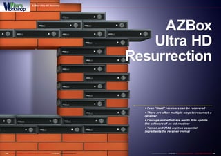
AZBox
Ultra HD
Resurrection
• Even "dead" receivers can be recovered
• There are often multiple ways to resurrect a
receiver
• Courage and effort are worth it to update
the software of an old receiver
• Yamon and JTAG are two essential
ingredients for receiver revival
AZBox Ultra HD Recovery
2. ■
■
146 TELE-audiovision International — The World‘s Largest Digital TV Trade Magazine — 07-08/2013 — www.TELE-audiovision.com
AZBox Ultra HD Recovery
A brick. That‘s what a receiver
is called that can‘t be resurrected.
It‘s dead and can only be used as a
paperweight.
That‘s exactly what happened to
my AZBox Ultra HD. I was experi-
menting with it and wanted to up-
load the latest E2 firmware to it.
As usual I didn‘t read the soft-
ware uploading instructions and,
just like that, my AZBox Ultra HD
became a brick; nothing worked
anymore.
So, what did I do? Bury it in my
garden or try to figure out what
went wrong?
You guessed it, I opted for the
latter choice.
How to
Turn a
Brick
Back
into a
Receiver
Vitor Martins Augusto
A look into Vitor's real-life Workshop:
doing the TTL recovery makes your bench
look as if you were doing open heart
surgery. Seeing that the otherwise dead
receiver is still responding to Putty is a
great reassurance.
In TELE-audiovision 08-09/2010 we presented the AZBox Ultra HD. In our current
report we describe how to recover a "dead" AZBox Ultra HD.
http://www.TELE-audiovision.com/TELE-satellite-1009/eng/azbox.pdf
3. 1
2
3
4 5
6
7
8
148 149TELE-audiovision International — The World‘s Largest Digital TV Trade Magazine — 07-08/2013 — www.TELE-audiovision.com www.TELE-audiovision.com — 07-08/2013 — TELE-audiovision International — 全球发行量最大的数字电视杂志
The older AZBox receivers, includ-
ing my Ultra HD, utilize an internal se-
rial interface. You can use it to hook
into the Bootloader and reflash the
firmware. But it‘s not as easy as it
sounds; the internal serial interface
operates at TTL levels (3.3 volts) as
opposed to the 12 volts of an RS232
interface.
If you would use a null modem cable
to directly connect this internal serial
interface to the COM port of a PC, a
hardware problem would result.
In a case like this you‘d need a TTL
adapter, something you could find
very inexpensively on eBay for around
2 Euros. It has to do with a USB TTL
adapter that would be automatically
recognized by a PC as a COM port.
This adapter uses the well-known Pro-
lific 2303 chip that is used in most USB
RS232 adapters. The one difference is
that in this case MAX232 comes into
play here for the level conversion.
But I opted for another solution: I
used an old Nokia DLR-2L data cable.
Since I wasn‘t using this cable any-
more, I simply cut off the Nokia con-
nector. Using an oscilloscope I figured
out that the red wire was RX, the green
wire was TX and the black wire as ex-
pected was ground.
An old CD-ROM audio cable for com-
puters provided a suitable connector
for the AZBox; the corresponding wires
just had to be connected together.
After an initial test, I realized I made
a mistake that almost everyone else
makes when it comes to serial trans-
missions: TX and RX naturally have to
have a criss-cross connection. Once
that was taken care of, it then worked
as expected.
Using Putty, a very well-known free-
ware terminal program, I was able to
access the AZBox Bootloader. It an-
nounced that the firmware was invalid.
This Bootloader is called YAMON (Yet
Another MONitor) and is far more com-
prehensive than standard Bootloaders
of older receivers. It lets you, among
other things, read the RAM memory or
send it to the PC.
Aside from that, you can also delete,
read and program the Flash memory.
Finally, it‘s also possible to start the
1. The Nokia DLR-2L cable features a TTL
to RS232 converter and can be used to
connect the COM-Port of a PC with a TTL
interface. If your computer does not have
a COM-port anymore, you can just use a
RS232 to USB converter. Bear in mind that
neither the Nokia-cable, nor the RS232 to
USB converter cross the TX and RX lines:
you will need to cross them yourself. Pay
special attention to just use TX, RX and
GND. The second pin on the AZBox PCB
is not to be used. Doing so can quickly
fry the circuit on the AZBox and then
you are definitely locked out of any TTL
restoration.
2. See the white dot on the PCB, close to
the 4 TTL pins? It marks the pin #1. On the
different AZBox receivers the pins have
always the same function:
Pin 1 – TX
Pin 2 – VCC (Warning: do not use this pin!)
Pin 3 – GND
Pin 4 – RX
3. When everything else fails, JTAG is your
last resort before having to flash the chip
externally. But before being able to do so
it is convenient to solder some pins on the
JTAG port, because the manufacturer left
those out.
4. In order to prevent accidental writing
to the flash chip a jumper exists. If not
closed, the JTAG cannot write to the flash
chip. This means that a jumper needs to
be soldered. Because the two pins are
really small, I just soldered a small wire.
Later on, instead of de-soldering it, I cut
the wires open, obtaining two small and
fragile pins, which can be closed without
further soldering.
5. This is the most difficult part of the
JTAG retrofitting, as you do need proper
equipment. I used a hot air soldering
station to obtain two 103 resistors from
an old motherboard. Using the same hot
air station, I soldered these two miniscule
resistors to the AZBox PCB, close to the
JTAG port.
6. The parallel JTAG adapter used in this
process consists of soldering a total of
four 100 Ohm resistors to a male DB25
connector. These are soldered each to pin
2, pin 3, pin 4 and pin 13. Finally, pins 20 to
25 have to be shunted. From each resistor
and from the shunted pins, connect wires,
as short as possible, to the pins of the
JTAG port on the AZBox PCB. Connect the
wires like in diagram right.
7. Connect the wires according to this
drawing
8. If TTL recovery seemed like open heart
surgery, JTAG flashing is equivalent
to brain surgery. Extra care has to be
taken to avoid that any wire touches the
receiver on the wrong spot. To prevent that
the casing of the open DB25 connector
touches the receiver, I used a bit of paper.
Put something heavy on the parallel
port cable, to prevent the cable from
accidentally moving, which could make
the thin wires go off. The receiver has to
be turned on during the JTAG process,
so beware that there is live current on the
open receiver. However, AZBox receivers
normally use an external power supply,
so you should not get hurt, even if you
touch the receiver. This is not the case on
receivers with build-in power supply. In
these cases you have to be extra careful
and advise other people in the house to
not get near the receiver.
4. 1
2
3 4
150 TELE-audiovision International — The World‘s Largest Digital TV Trade Magazine — 07-08/2013 — www.TELE-audiovision.com
Putty
1. Before starting Putty you need to figure
out which COM-port was assigned to the
USB adapter. The easiest way to do so is to
open the device manager and check on the
Ports (COM & LPT) section, what the port
attributed to the Prolific USB-to-Serial is.
2. Open Putty and configure the session
to use the Serial port. Configure it to
match the port number and set the Speed
to 115200 baud (bits per second). Then
click the Open button to start the session.
Finally, you can turn on the receiver.
3. If the boot loader has not been whipped
you should be greeted by YAMON. You can
stop the boot procedure of the receiver
with CTRL-C, but if the kernel is corrupt or
erased YAMON will stop anyway.
4. The next step is to setup the network.
You need three commands:
- “setenv ipaddr 192.168.xxx.yyy” will
set the receiver’s IP address. Replace
xxx and yyy with suitable values for your
network. Remember that xxx must be a
unique value.
- “setenv subnetmask 255.255.255.0” will
set the receiver’s subnet mask, which
usually is 255.255.255.0.
- “setenv gateway 192.168.xxx.zzz” will
set the gateway. This is normally the IP
address of your router.
If these three steps have been correctly
done you can initialize the network with
“net init” and start it with “net up”.
execution of programs at any RAM ad-
dress.
The procedure is always to inter-
rupt the startup of YAMON with CTRL-
C. Now the network interface is con-
figured and activated. Finally, a TFTP
server is started on the computer with
which you can load an recovery image
into RAM.
You start with this and the receiver
boots in a minimized Linux operating
system. Next you copy, as you would
normally, an recovery image together
with the update program to /tmp. The
rights of the program must be changed
so that it can be executed.
When you start „update“ using the
name of the recovery image, the re-
ceiver is reflashed after which the de-
sired firmware can be flashed normally
via USB and AZUp.
No sooner said than done; I was suc-
cessful in the first attempt: my AZ-
Box Ultra HD started up like I initially
wanted with the current E2 OpenRSI
firmware.
Yes it was nice, but I still wasn‘t sat-
isfied. I felt that the recovery proce-
dure was far too complicated. There
had to be a simpler way. I mean, if you
already have the YAMON Bootloader, it
should be possible to use it to directly
burn the Flash.
So, I tried to do exactly that. My
plan: load the recovery image into the
RAM, delete the Flash and then reflash
5. 1 2
3
4
5
6 7
8 9
10 11
12
152 153TELE-audiovision International — The World‘s Largest Digital TV Trade Magazine — 07-08/2013 — www.TELE-audiovision.com www.TELE-audiovision.com — 07-08/2013 — TELE-audiovision International — 全球发行量最大的数字电视杂志
TTL Recovery
1. To do the recovery, you need to enter
YAMON as described before and then
it is essential to configure and start the
network adapter of the AZBox.
2. Now we want to load the recovery image
called “vmlinux.bin” contained in the
recovery archives. Do not press enter, yet!
3. You need to copy the required files to a
folder, first.
4. Now it is time to start PumpKIN, the
freeware TFTP server.
5. Configure the path to the folder were
you placed the recovery files for your
AZBox.
6. Now you can press ENTER on the Putty
window and hopefully the “vmlinux.bin”
file will be loaded into the RAM of the
AZBox.
7. Type the “go” command inside the
Putty window to start the recovery Linux
from RAM. The usual start-up messages
appear…
8. …and only a short while later, you will
be prompted for the AZBOX login. Use
“root” for login and you may or may not
have to enter the password, which will be
“azbox”.
9. If everything went well, you are now
logged in.
10. Change to the “/tmp” folder with “cd /
tmp”.
11. And then confirm your network
configuration with the command
“ifconfig”. It is good to have the rooter
configured as a DHCP server, which
automatically provides the network
configuration.
12. Use your favourite FTP client (we like
the free FileZilla) and transfer the backup
kernel and the “update” file to “/tmp” of
your AZBox. Use the IP address obtained
in the last step and don’t forget to specify
the password, if required.
using the image in the RAM.
This would somewhat simplify the
recovery procedure.
First test: Image loaded into RAM,
Flash deleted. But when I tried to
flash the RAM with the image, YAMON
refused to cooperate. At this point it
wasn‘t clear why this happened. It
didn‘t matter, I thought.
So, I restarted the receiver and per-
formed the above described procedure
again. Yeah, right! In the heat of the
moment I managed to delete the EN-
TIRE Flash memory including the Boot-
loader. So, it looked like my receiver
would be a paperweight after all. Then
again…
What about JTAG? I wrote about in-
corporating a JTAG interface back in
the 10-11/2011 issue of TELE-audiovi-
sion. Would it work with that? It didn‘t
take me long to figure out everything
that would need to be done:
the hole: first you have to add solder.
Because of the larger amount of sol-
der, it remains in a liquid state a little
longer when heat is removed so that
the pump is able to suck the solder
out. If there‘s only a little solder, it will
solidify before the pump has a chance
to suck it out.
Soldering in the pins was easy. For
the jumper I used a thin bendable wire.
You need only the solder already on
the circuit board to attach the jumper
wire.
Lastly, the resistors. Where on Earth
am I going to get these from? Here
it pays not to throw out old mother-
boards. The required resistors can
usually be found on those kinds of cir-
cuit boards; all you have to do is unsol-
der them. But you won‘t get far using a
normal soldering iron.
You‘d be far better off using a hot
air soldering station. They‘re really
not that expensive and will quickly pay
• The JTAG pin holes are not occupied and need to be un-
soldered. First you have to remove the existing solder and
then solder pins in place.
• A jumper has to be added that deactivates the write-
protection on the Flash memory. It involves bridging R309
located near the processor.
• Two SMD type 103 resistors (quad version) need to be
soldered in.
• The necessary JTAG interface with the parallel port
must be crafted. Four 100K resistors are needed as well as
a DB25 connector.
No problem, I thought, so I immediately sat down at my
work bench. The solder is removed using a soldering iron
and a desoldering pump. There‘s a little trick to clearing out
6. 13 14
15 16
1 2
3 4
5
154 155TELE-audiovision International — The World‘s Largest Digital TV Trade Magazine — 07-08/2013 — www.TELE-audiovision.com www.TELE-audiovision.com — 07-08/2013 — TELE-audiovision International — 全球发行量最大的数字电视杂志
TTL Recovery
13. In the Putty window, confirm you
received the files with the “ls” command.
Notice that the “update” file is listed
in grey. This means that it cannot be
executed!
14. Use the “chmod 755 update” command
to change the privileges, so that “update”
can be executed.
15. Repeat the “ls” command: “update” is
now listed in green, meaning that it can be
executed.
16. Execute the command “./update
backup_kernel_344” to flash the backup
kernel into the flash. This will take a few
minutes and the receiver will then restart
automatically. It may be necessary to turn
the receiver off and on again. It will boot
with a kernel that can be upgraded using
the normal procedure with a USB pen and
AZUp. Congratulations! The receiver is
alive again.
for themselves when used to unsol-
der chips or small SMA components.
You can get a good model starting at
around 150 Euros.
In just a few seconds I unsoldered
two matching resistors labeled 103
from an old motherboard using a hot-
air soldering iron and soldered them to
the AZBox circuit board. It‘s nice that
this little resistor is sucked correctly
onto the contacts thanks to the sur-
face tension of the solder.
It‘s not easy to check this with the
naked eye. It‘s actually easier than it
looks.
The JTAG interface was finished in a
few minutes; I could now get started.
Using the OpenSource OpenOCD soft-
ware the Flash process is run. But I
soon became disillusioned: the Flash
process is slow. Not slow in the normal
sense, but snail slow.
According to my calculations the
complete 8MB flash process would take
eight weeks to complete! So I decided
to have a look at the firmware file with
a hex editor.
It‘s easy to recognize on the
„straight“ hexadecimal address if a
new memory location starts. You have
to think of the Flash memory like a
diskette on which different files are
stored.
In between the files up until the next
„straight“ memory address there‘s al-
ways a free space that is filled with ei-
ther &H00 or &HFF.
Since the kernel is also housed in the
Flash and I already had a file like this
on my PC, I could quickly figure out
where to find it in the Flash. It definite-
ly pays to snoop around in a Flash file;
the OpenSource Hex editor „Frhed“ is
perfect for this.
My investigation found that the 8192
KB is divided is follows:
• &H000000-&H0040000
– First Bootloader
• &H004000-&H0080000
– YAMON
• &H008000-&H0700000
– Linux Kernel
• &H070000-&H07FFFFF
– First File System
It should be good enough to only
write the first &H80000 bytes instead
of the complete &H800000. This flash
process should be completed in just
one night.
Therefore, I copied the first &H80000
bytes into a new file using the Hex edi-
tor and then flashed it using OpenOCD.
Sure enough, the next morning I
was able to start my receiver as far as
YAMON. Next I transferred the recov-
ery image again into RAM via TFTP.
To make sure I didn‘t once again
lose both the Bootloader and YAMON, I
used the Hex editor to delete the first
&H80000 bytes and then flashed the
remaining file starting at memory lo-
cation &H008000. This process only
needed a few minutes.
Now look at that: the receiver start
up again and I was able to quite nor-
mally upload the firmware using AZUp.
The receiver was successfully raised
from the dead.
And there you have it: with the help
of a TTL adapter and the availability of
YAMON, you can directly write a kernel
to every AZBox.
You won‘t ever have to use a dead
AZBox as a brick when building a new
house because you can simply bring it
back to life!
This AZBox Ultra HD receiver has re-
ally grown on me; after a few sleep-
less nights, some soldering and incor-
porating a JTAG interface, I am now
much more intimately familiar with the
inside of this box than with any other
receiver.
JTAG
1. If you can’t enter YAMON, because the flash has been
completely wiped off then you must use the JTAG route to
recover your AZBox. Download OpenOCD and copy the AZBox
configurations to the correct folders. Google for “azbox jtag” and
you should easily find the required files with instructions. You
need a copy of the flash contents (a file with exactly 8MB), usually
found with the name “az3_nor_flash.rar”. You then need to copy
“azbox.cfg” to the “board” folder in the OpenOCD installation
tree and “smp8634.cfg” to the “target” folder. Now open two DOS
shells, using WINDOWS-R. Enter “cmd” in the pop-up window. In
both windows, go into the installation folder of OpenOCD and then
in the “bin” subfolder.
2, 3. Arrange both windows vertically, so you can monitor both.
In the upper window, enter the command “openocd –f interface
parport_dlc5.cfg –f boardazbox.cfg”. Naturally you must have the
AZBox turned on and the JTAG-interface connected. Type “telnet
localhost 444” in the lower window, but wait until OpenOCD starts
successfully in the upper window.
4. Press ENTER in the lower window. Now you can issue
commands in the lower window and see the responses in both
windows. Start with the following commands:
- halt
- reset halt
- reset init
5. If everything went well so far, you can continue with these
commands:
- flash probe 0
- flash erase_sector 0 0 63
- flash write_image az3.bin 0 bin
- flash write_bank 0 az3.bin 0x0
This will now take literally ages. The window will show the
progress:
Programming at ac000000, count 00800000 bytes remaining
Programming at ac000100, count 007fff00 bytes remaining
Programming at ac000200, count 007ffe00 bytes remaining
However, you do not have to wait until the whole flash is
programmed. That would take almost two weeks, at least on my
computers. I tried two different ones and the results were the
same. All you need to do is just to flash the first &H80000 bytes,
which contain the first boot loader and the YAMON ROM monitor.
This means that you can simply turn off the receiver as soon
as the message “Programming at ac080000, count 0077FFFF
bytes remaining” appears. Once this happens and all went well,
you should be able to start YAMON again. You then are back in
business, as you can repeat the regular TTL flashing process. But
still, I found a better way of doing it… Read on!
7. 1
2
3
4
5
6
7
156 TELE-audiovision International — The World‘s Largest Digital TV Trade Magazine — 07-08/2013 — www.TELE-audiovision.com
Flash Dump with Yamon
1. The first thing you should always do
with any of your receivers is to dump
the flash, in case things go wrong. Start
YAMON using the TTL interface and by
pressing CTRL-C as prompted.
2. Configure and start the network and
don’t forget to start PumpKIN.
3. Use the “fwrite” command of YAMON to
dump the flash into a file.
4. PumpKIN asks if we really want to
receive the file. Yes we do!
5. YAMON states the flash contents have
been successfully transferred.
6. And so does PumpKIN.
7. Right click on the dumped file and
confirm that the file size is exactly 8MB
(8.388.608 bytes). If so, you have a good
backup copy of your flash.
8. 1 2
3 4
5 6
158 TELE-audiovision International — The World‘s Largest Digital TV Trade Magazine — 07-08/2013 — www.TELE-audiovision.com
Flashing in Yamon
1. The dumped flash file contains both boot loaders in the first
&H80000 bytes. Use your favourite HEX-editor to delete these
bytes. I use the free software Frhed for this.
2. Select the first byte and then shift-select the byte on position
0x7ffff. Notice that the next bytes show “-rom1fs-“ which is the
label of the kernel!
3. Press the DEL-key to delete the selected bytes. Confirm that
you are deleting x0 to x7ffff.
4. Save the resulting bytes into a new file.
5. You will obtain a new file with exactly 7.864.320 bytes. It
contains the complete flash image except the two boot loaders.
6. This file can be written directly from within YAMON to the
flash chip using the “pflash” command. Make sure that the file is
loaded into &Hb0100000 and its size is &H780000. This makes the
recovery process much faster, as you do not have to start Linux
from RAM and then transfer files using FTP.