SlideShare ist ein Scribd-Unternehmen logo
1 von 39
Downloaden Sie, um offline zu lesen
Reinforced Masonry
Working Stress Design of flexural members

                       b                         strain          stress
                                                      εm            fm
                                                                            Cm = fmb kd/2
                                          kd
       d                           n.a.                                                  M

                                                                           Ts = Asfs
t                                               εs            fs/n
                     grout           As                                          As
                                                                            ρ=
                      unit                                                       bd


           Ref: NCMA TEK 14-2 Reinforced Concrete Masonry
                BIA Tech. Note 17 Reinforced Brick Masonry - Part I
                BIA Tech. Note 17A Reinforced Brick Masonry - Materials and Construction

                                                                 Masonry Structures, slide 1


Reinforced Masonry
Working Stress Design of flexural members
    Assumptions
     1. plane sections remain plane after bending
        (shear deformations are neglected, strain distribution is linear with depth)
     2. neglect all masonry in tension
     3. stress-strain relation for masonry is linear in compression
     4. stress-strain relation for steel is linear
     5. perfect bond between reinforcement and grout
         (strain in grout is equal to strain in adjacent reinforcement)
     6. masonry units and grout have same properties

       from Assumption #5, at any particular fiber : ε si = ε mi
                                          f si f mi            Es
       from Assumption s #3 and #4 :          =              f si = f mi = nf mi
                                          E s Em               Em
                                                     fm   f n                 1− k
       from geometry of stress distribution :           = s       f s = nf m
                                                     kd d − kd                   k


                                                                 Masonry Structures, slide 2
Reinforced Masonry
Working Stress Design of flexural members
 from equilibrium, C = T :
                 f m bkd                                  1−k
                         = As f s = ρ bd f s = ρ bd n f m
                     2                                     k
                                       1− k
                          k / 2= ρ n                  k 2 + 2 ρnk − 2 ρn = 0
                                        k
 from equilibrium: ∑ M about C m = 0
                        M s = As f s jd = ρbd 2 jf s    where jd=d-kd/3 or j=1-k/3

  If fs=Fs then moment capacity will be limited by reinforcement.

 Allowable reinforcement tensile stress per MSJC Sec.2.3.2:
     Fs=20 ksi for Grades 40 or 50; Fs=24 ksi for Grade 60
     Fs=30 ksi for wire joint reinforcement
 Allowable reinforcement tensile stress per UBC Sec.2107.2.11 :
     Fs= 0.5fy < 24 ksi for deformed bars; Fs= 0.5fy < 30 ksi for wire reinforcement
     Fs= 0.4fy < 20 ksi for ties, anchors, and smooth bars

                                                                Masonry Structures, slide 3


Reinforced Masonry
Working Stress Design of flexural members


  from equilibrium:    ∑ M about T    s   =0

                 M m = 0.5 f m bkdjd = 0.5 f m jkbd 2


     If fm= Fb then moment capacity will be limited by masonry.
                 UBC 2107.2.6 & MSJC Sec.2.3.3.2:
                          Fb=0.33f’m


                                                                Masonry Structures, slide 4
Reinforced Masonry
WSD: Balanced Condition
                                                                           fm = F b

Definition:     The balanced condition occurs                    kbd
                                                                                   C = fmb kd/2
when the extreme fiber stress in the masonry is
equal to the allowable compressive stress, Fb,            d
and the tensile stress in the reinforcement is
equal to the allowable tensile stress, Fs.
                                                                                  T = As fs
                                                               fs/n = Fs /n

  •       For any section and materials, only one unique amount of balanced
          reinforcement exists.
  •       Although balanced condition is purely hypothetical case, it is useful because it
          alerts the engineer to whether the reinforcement or the masonry stress will
          govern the design. Balanced stresses are not a design objective.


                                                                  Masonry Structures, slide 5


Reinforced Masonry
WSD: Balanced Condition
                                 from geometry:               from equilibrium: C=T
                                                     Fs
                      fm = Fb               Fb +
                                   Fb                n               d
                                        =                      Fb b kb = ρb b d Fs
                                   kb d          d                   2
              kbd
                                                                   Fk      F       n
      d                                      Fb                ρb = b b = b
                                   kb =                            2 Fs 2 Fs ( n + Fs )
                                                  Fs
                                          Fb +                                      Fb
                                                  n
            fs/n = Fs /n
                                              n                      ⎡      n      ⎤⎡ 1 ⎤
                                  kb =                          ρb = ⎢             ⎥⎢           ⎥
                                          n + Fs /Fb                 ⎣ n + Fs / Fb ⎦ ⎣ 2Fs / Fb ⎦


                                                                  Masonry Structures, slide 6
Example: Balanced Condition
Determine the ratio of reinforcement that will result in a balanced condition per UBC.
Given: f’m = 2000 psi and Grade 60 reinforcement


        Fb = 0.33 f'm = 667 psi        Fs = 24 ksi for Grade 60 reinforcement
        E m = 750 f'm = 1500 ksi       E s = 29,000 ksi

               E s 29,000
        n =       =       = 19.3
               Em   1500


               ⎡       19.3      ⎤⎡       1      ⎤
        ρb = ⎢                                     = 0.48%
               ⎣ 19.3 + 24/0.667 ⎥ ⎢ 2 x24/0.667 ⎥
                                 ⎦⎣              ⎦


                                                               Masonry Structures, slide 7


Design Strategy for RM Flexural Design
Procedure for sizing section and reinforcement for given moment.

              Calculate ρb knowing f’m and fy
               determine Fb from f’m
               determine Fs from fy
               determine Emfrom f’m
               determine n = Es/Em


              Size section for some ρ < ρb                   Note: Section must also be
                determine k and j                            sized for shear.
                bd2 = M/ρjFs
                select b and d using common units


           Size reinforcement                             Check design
             As = M/Fsjd                                   Ms = AsFsjd > M
             select number and size of rebars              fb = M/0.5jkbd2 < Fb

                                                               Masonry Structures, slide 8
Example: Reinforced Masonry
   Design a beam section for a moment equal to 370 kip-in. Prisms have been
   tested and f’m is specified at 2000 psi. Use Grade 60 reinforcement and 8”
   CMU’s.
                  1. From previous example, ρb = 0.48%
                  2. Estimate ρ to be slightly lower than ρ so steel will govern.
                                                           b
                     A good estimate is ρ = 0.4%
                  3. Solve for k :
                        k 2 + 2 ρnk − 2 ρn = 0
                        2 ρn = 2( 0.004 )( 19.3 )= 0.154
                        k 2 + 0.154 k − 0.154 = 0
                        k = 0.323 j = 1 − k / 3 = 0.892
                   4. Solve for bd 2 :
                         bd 2 = M / ρ j F s
                         bd 2 = ( 370 kip − in ) /( 0.004 )( 0.892 )24 ksi ) = 4321 in 3

                                                                             Masonry Structures, slide 9


   Example: Reinforced Masonry
   5. Select dimensions of beam using 8” CMU’s:
      b = 7.63”                                                     4 - 8” CMU’s
      dreq’d = [4321 / 7.63]0.5 = 23.8”                                                             d=27.8”
      use four units and center bars in bottom
      unit, d = 27.8”
   6. Estimate amount of reinforcem ent :
      As req' d = M / Fs j d                                                             7.63”

      As req' d = (370 kip - in) / (24 ksi) (0.892) (27.8) = 0.62 in     2
                                                                             use 2 #5' s (0.62 in 2 )

7 . Check design:
   ρ = Αs / bd = 0.62 in 2 / (7.63quot; ) ( 27.8quot; ) = 0.00292
   k 2 + 2 ρnk − 2 ρn = 0      k = 0.284 j = 1 − 0.284 / 3 = 0.905
  Μ s = Αs Fs j d = ( 0.62 in 2 )( 24 ksi )( 0.905 )( 27.8quot; ) = 374 kip − in. > 370 kip − in. OK
                                        ( 370 kip − in x 1000 )
   f m = Μ / 0. 5 j k d 2 =                                                = 488 psi < 667 psi ok
                              ( 0.5 )( 0.905 )( 0.284 )(7.63quot; )( 27.8quot; ) 2


                                                                             Masonry Structures, slide 10
Flexural Capacity of Partially Grouted Masonry
Case A: neutral axis in flange                                                 * per MSJC Sec. 2.3.3.3
                                                                    flange
                        b = 6t or 72” or s*                            b
                 tf                                     kd
                                                                                      neutral
                                                    d
         t                                                                            axis
                                                                          As
                                                    As per width b

    If neutral axis is in flange, cracked section is the same as a solid rectangular
    section with width “b.” Therefore, depth to neutral axis from extreme
    compression fiber may be calculated using:
                                                                     As
                           k 2 + 2 ρnk − 2 ρn = 0               ρ=
                                                                     bd

If kd < tf assumption is valid, determine moment capacity as for rectangular section.
If kd > tf assumption is not valid, need to consider web portion.


                                                                          Masonry Structures, slide 11


Shear Design of Reinforced Masonry
                                           s
                                                               Cm
                                                        Vm
d
                                                 Vs Vext.
                                           Viy
                                                             Asfs
                                      Vd
             R                                 Basic shear mechanisms:
                                               before cracking: Vext = Vint = Vm + Vd + Viy + Vs
Once diagonal crack forms:
•       Vm reduces                    •    flexural stresses increase
•       dowel action invoked          •    fsa is related to Mb

Presence of shear reinforcement will:
    •   restrict crack growth         • resist tensile stress
    •   help dowel action

                                                                          Masonry Structures, slide 12
Shear Design of Reinforced Masonry


after cracking: Vext = Vint = Vs = nAvfs       where n is the number of transverse
                                               bars across the diagonal crack.
                                               Assuming a 45 degree slope, n=d/s
                             Vs = (d/s)Avfs


                          Av Vs Vs                UBC Sec. 2107.2.17 (Eq. 7.38)
                            =   =                 MSJC Sec. 2.3.5.3 (Eq. 2-26)
                          s df s dFs


                                                             Masonry Structures, slide 13


Shear Design of Reinforced Masomry
 Flexural shear stress
                  dx
            C
  M                         C + dC     M + dM        fvbdx
                            na
       jd


            T              T + dT             T                 T + dT

                       fvb dx = dT = dM/jd
                       fv = (dM/dx)/bjd

                                 V
                         fv =        UBC Sec. 2107.2.17 (Eq. 7-38)
                                 bjd
                                 V
                          fv =
                                 bd MSJC Sec. 2.3.5.2.1 (Eq. 2-19)

                                                             Masonry Structures, slide 14
Shear Design of Reinforced Masonry
Allowable shear stresses for flexural members per UBC and MSJC


 UBC Sec. 2107.2.8.A and MSJC Sec. 2.3.5.2.2(a):
 members with no shear reinforcement
             Fv = 1.0 f'm < 50 psi              UBC Eq. 7-17; MSJC Eq. 2-20


  UBC Sec. 2107.2.8.B and MSJC Sec. 2.3.5.2.3(a):
  members with shear reinforcement designed to take the entire shear

                Fv = 3.0 f'm < 150 psi          UBC Eq. 7-18; MSJC Eq. 2-23


                                                                Masonry Structures, slide 15


Shear Design of Reinforced Masonry
Allowable shear stresses for shear walls per UBC and MSJC

UBC Sec. 2107.2.9.i and MSJC Sec. 2.3.5.2.2(b):
walls with in-plane flexural reinforcement and no shear reinforcement
        M              1     M                 M
  for      <1     F v = ( 4 − ) f 'm <( 80 − 45 ) psi           UBC Eq. 7-19; MSJC Eq. 2-21
        Vd             3     Vd                Vd
          M
  for        ≥1    F v = 1.0 f 'm < 35 psi                      UBC Eq. 7-20; MSJC Eq. 2-22
          Vd

UBC Sec. 2107.2.9.ii and MSJC Sec. 2.3.5.2.3(b):
walls with in-plane flexural reinforcement and shear reinforcement designed
to take 100% of shear
           M             1      M                     M
    for       <1     Fv = ( 4 −    ) f'm < ( 120 − 45    )psi    UBC Eq. 7-21; MSJC Eq. 2-24
           Vd            2      Vd                    Vd
           M
    for       ≥1    F v = 1.5 f 'm < 75 psi h                    UBC Eq. 7-22; MSJC Eq. 2-25
           Vd

                                                                Masonry Structures, slide 16
Shear Design of Reinforced Masonry
Moment-to-Shear Ratios

         For a single-story                    For piers between openings
         cantilevered shear walls
                                                       M
                  d
     V                                    V


                                                           d
 h                                         h


                       M                                         M

           M Vh h                                    M Vh / 2 h
             =  =                                       =    =
           Vd Vd d                                   Vd   Vd   2d

                                                     Masonry Structures, slide 17


Shear Design of Reinforced Masonry
Additional MSJC Requirements

  MSJC Sec. 2.3.5.3.1
    smax = d/2 or 48”
  MSJC Sec. 2.3.3.4.2
    minimum reinforcement perpendicular to shear reinforcement = Av/3
    smax = 8 ft

 MSJC Sec. 2.3.5.5
   design for shear force at distance “d/2” out from support


                      Vdesign             Vdesign

               d/2

                                                     Masonry Structures, slide 18
Shear Design of Reinforced Masonry
        Shear Design Strategy for Reinforced Sections

                          Start


          Determine Flexural Tension Stress                  Determine Fv Assuming Shear
                   ft= -P/A+Mc/I                          Reinforcement to take 100% of Shear

   consider as no                                                                        no
                  is ft>Ft?                                                                     Resize
  unreinforced                                                                   is fv<Fv?
                                                                                                Section
                              yes
                                                                                      yes
         Determine Maximum Design Shear
                                                                       Provide Reinforcement to Take
                                                                               100% of Shear
               Determine Shear Stress                                           Av   V
                          V    V                                                   = s
                    fv =    or                                                   s   dFs
                         bjd bd                      no
                                                                 yes
          Determine Fv Assuming No Shear             is fv<Fv?                     End
                  Reinforcement

                                                                        Masonry Structures, slide 19


   Example: Design of RM Shear Wall
    Determine the maximum lateral force, Hwind per UBC and MSJC

                  6’-8”             8” CMU wall
                120 psi             Type S - PCL mortar
                                    solidly grouted f’m=3000 psi

                                    #4 @ 32”

                                    2 - #8’s each end of wall
8’-0”


                                      Case A:    neglect all reinforcement
                                      Case B:    consider vertical reinf., neglect horizontal reinf.
                                      Case C:    consider vertical and horizontal reinf.
                 6’-4”                Case D:    design horizontal reinforcement for max. shear


                                                                        Masonry Structures, slide 20
Example: Design of RM Shear Wall
Case A: neglect all reinforcement
  per UBC:                                                   7.63 × 80 2
                                                        Sg =             = 8139 in3
   flexure                                                       6
             M                  96 × H
       - fa + = Ft      − 120 +        = 40 x 1.33 H = 14 ,684 lbs. = 14.7 kips
             S                   8139
   shear
           Fv = [ 34 psi + 0.2 fa dead ] x 1.33 = [ 34 + 0.2 ( 120 )] x 1.33 = 77.1 psi
                                             77.1 psi
           Vmax = Ae Fv = ( 7.63 x 80.0 )(            ) = 47.1 kips
                                              1000
  per MSJC:
   flexure                                      96 × H
            - fa + M / S = Ft        − 120 +           =0     H = 10 ,174 lbs . = 10.2 kips
    shear                                        8139
           Fv = 60 + 0.45 ( 120 ) = 114 psi > 1.5 f'm = 82.2 psi
           Fv = 1.33 × 82.2 psi = 109 psi
                 2       2
           Vmax = Fv bt = ( 109 psi )( 7.63 x 80 ) = 44.3 kips
                 3       3
                                                                      Masonry Structures, slide 21


Example: Design of RM Shear Wall
Case B: consider only vertical reinforcement
Flexure by UBC or MSJC: neglecting fa
 Ms = AsFsjd = 2 x 0.79 in2 (1.33 x 24 ksi) (0.9 x 72.0”) = 3268 k-in            Hwind = 34.0 kips
                  lumping 2 - #8’s                              ave. d for 2 bars


 Shear per UBC Sec.2107.2.9 or MSJC Sec.2.3.5.2
              8.0'
   M/Vd =          = 1.33 > 1
              6.0'
           M
     for      > 1 Fv = 1.0 f 'm < 35 psi Fv = 1.33 x 35 psi = 46.6 psi
           Vd

     for UBC Vmax = bjdFv = ( 7.63quot; )( 0.9 )( 72quot; )( 46.6 psi ) / 1000 = 23.0 kips governs

     for MSJC Vmax = bdFv = ( 7.63quot; )( 72quot; )( 46.6 psi ) / 1000 = 25.6 kips governs


                                                                      Masonry Structures, slide 22
Example: Design of RM Shear Wall
Case C: consider all reinforcement
Flexure by UBC or MSJC: same as case B
Shear per UBC Sec. 2107.2.17 or MSJC Sec.2.3.5.3
   Vmax= Vs=(Av/s)Fsd = (0.20 in2/32”)(24 ksi x 1.33)(72”) = 14.4 kips governs


Overall shear per UBC Sec. 2107.2.9.C or MSJC Sec. 2.3.5.2.3 (b)
           M
     for      > 1 F = 1.5 f'm ≤75 psi F = 1.5 3000 = 82.2psi>75 psi
                   v                    v
           Vd
                  Fv = 1.33x 75 psi= 100 psi

                          V     (14.4 kips x 1000)
              UBC f v =       =                     = 30.7 psi < 100 psi okay
                          bjd    (7.63)( 0 .9 )(72)

                          V (14.4 kips x 1000)
             MSJC f v =      =                 = 27.7 psi < 100 psi okay
                          bd    (7.63)(72)

                                                                 Masonry Structures, slide 23


Example: Design of RM Shear Wall
Case D: design horizontal reinforcement for maximum shear strength
   Vmax = Fvbjd = ( 100 psi)( .63)(0.9 )(72)/ 1000 = 49.4 kips > 34 kips oka govern
                            7                                              y      s
   Av /S = Vmax/Fsd = 49.4 kips/( .33 x 24 ksi)( ) = 0.0215in2 per in.
                                1              72
   u sing #4 rebars(Av = 0.20 in2 ) s = 0.20 / 0.0215 = 9.3quot; use # @ 8 in. horiz
                                                                 4             ontal
                                  Summary: Hmax, kips

                Case        Consideration               UBC         MSJC
                 A      No steel
                         No steel                        14.7*
                                                         14.7*           10.2*
                                                                         10.2*
                         vertical steel                  24.3            27.0
                 B      vertical steel                   23.0            25.6
                         no horizontal steel
                        no horizontal steel
                         vertical steel and             15.2         15.2
                 C      vertical steel and              14.4         14.4
                         #4 @ 32” horizontal steel
                        #4 @ 32” horizontal steel

                 D      #4#4 @ 8” horizontal
                           @ 8” horizontal               34.0*
                                                         34.0*           34.0*

                                                            *flexure governs

                                                                 Masonry Structures, slide 24
Flexural Bond Stress
                                                            M = Tjd
                                                            M + dM = (T + dT)jd
                                                            dM = dT jd
             dx                                             dT = dM/jd

                                      C + dC          U = bond force per unit length for group of bars
    C
                                                      U dx = dT = dM/jd
                                                      U = (dM/dx)/jd = V/jd
M                                                                                U
                  dx                  jd              u = flexural bond stress =
                                               M + dM                            ∑o
                                                      where ∑ o = sum of perimeters of all bars in group
         T                        T + dT
                                                                         V
                                                                   u=             UBC Sec. 2107.2.16 Eq. 7-36
                   dx                                                   Σ ο jd
                                  U
                                             T + dT         allowable bond stress per UBC Sec.2107.2.2.4:
    T                                                           60 psi for plain bars
                                                                200 psi for deformed bars
                             dx                                 100 psi for deformed bars w/o inspection


                                                                                  Masonry Structures, slide 25


    Development Length

                                                        uπ d b

                                       db                                        As fs

                                                       ld

                  As fs = uπdb ld
                  πd b
                         2
                              fs = uπdb ld
                   4
                        f s db
                  ld =         = 0.002 db fs for u = 125 psi UBC Sec. 2107.2.2.3 Eq.7 - 9
                        4u
                  ld = 0.0015 db Fs for u = 167 psi MSJC Sec . 2.1.8.2 Eq . 2 − 8


                                                                                  Masonry Structures, slide 26
Embedment of Flexural Reinforcement
UBC Sec. 2106.3.4 and MSJC Sec.2.1. 8.3
Rule #1: extend bars a distance of “d” or “12db” past the theoretical cutoff point
Rule #2: extend bars a distance of “ld” past the point of maximum stress
  Example for shear wall:


                                   bars “a”
                                                                                   Moment Diagram
                                                                         (#2)
                                                                         > ld
                                                      (#1)
                                                   d or 12db


                                                                                           theoretical cutoff point
                                                                                           capacity with bars “a”
                        bars “b”


                                                        (#2)
                                                        > ld
                                                                                  moment capacity
                                                                                with bars “a” and “b”
                                                                                       Masonry Structures, slide 27


Combined Bending and Axial Loads
Code Requirements
UBC Sec. 2107.1.6.3                                                         fa fb
use unity formula to check compressive stress:                                + < 1.0
                                                                            Fa Fb
  UBC Sec. 2107.1.6.1                         UBC Sec. 2107.2.15
            P                                                  M                Note: unity formula is conservative -
                                                                                better approach is to use P-M
                                                                                interaction diagram.


                                                                                   M
                                                As fs                    fb =              ( Eq .7 − 31 )
                                                                                2 jkbd 2
     fa = P/Ae                                                      kd
                                                               jd
UBC Sec. 2.14.2
if h’/t >30 then analysis should consider effects of deflections on moments

MSJC Sec. 2.3.3.2.2                      fa + fb < 1/3 f’m provided that fa < Fa
In lieu of approximate method, use an axial-force moment interaction diagram.

                                                                                       Masonry Structures, slide 28
Axial Force-Moment Interaction Diagrams
General Assumptions
 1. plane sections remain plane after bending
       • shear deformations neglected
       • strain distribution linear with depth
2. neglect all masonry in tension
3. neglect steel in compression unless tied                                    Strain    Stress
4. stress-strain relation for masonry is linear in compression                   εm       fm
5. stress-strain relation for steel is linear
6. perfect bond between reinforcement and grout                                                   Cs
       • strain in grout is equal to strain in adjacent
            reinforcement
7. grout properties same as masonry unit properties

                                              P

                                                     M
                                                                          εs
                                                                                        Ts=Asfs

                                                                 Masonry Structures, slide 29


Axial Force-Moment Interaction Diagram
Out-of-Plane Bending of Reinforced Wall
                       Pa
                  Mb

                  d = t/2
                                    Range “a”:
                                    large P, small M, e=M/P < t/6
 unit width = b


                                    Pa = 0.5(fm1 + fm2)A

                                    Ma= 0.5(fm1 - fm2)S where S = bt2/6


                             fm2
         fm1
                        em
                   Cm


                                                                 Masonry Structures, slide 30
Axial Force-Moment Interaction Diagram
Out-of-Plane Bending of Reinforced Wall
                       Pb
                 Mb
                 d = t/2               Range “b”
                                       medium P, medium M, e > t/6, As in compression
unit width = b


                                        0.5 < α < 1.0 for section with reinforcement at center
                                               t αt
                                        em =    −
                                               2 3
                                                      fm 1
   fm1                                  Pb = C m =         αtb
                       em                              2
                  Cm
                                        M b = C m em
                           αt

                                                                           Masonry Structures, slide 31


Axial Force-Moment Interaction Diagram
Out-of-Plane Bending of Reinforced Wall
                       Pc
                 Mc
                                     Range “c” small P, large M, e > t/6, As in tension
                 d = t/2

                                        α < 0.5 for section with reinforcement at center
unit width = b


                                               t αt
                                        em =    −
                                               2 3
                                                                         fm 1
                                         Pc = C m − Ts       Cm =             αtb     Ts = As fs
                                                                          2

                                         f s ⎡ d − αt ⎤        ⎡ 0. 5 − α ⎤           t
                                            =           fm 1 = ⎢            f for d =
   fm1                                   n ⎢ αt ⎥
                                              ⎣       ⎦        ⎣     α ⎥ m1
                                                                          ⎦           2
                      em
                                Ts
                  Cm                                               t
                                         M c = C m em + Ts ( d −     )
                  αt                                               2

                                                                           Masonry Structures, slide 32
Axial Force-Moment Interaction Diagram
   Out-of-Plane Bending of Reinforced Wall
                        Range “a”                                     Range “b”                                             Range “c”
 e=0; M=0
fm1= fm2=Fa      fm1= Fb= f’m/3
  P=Fa A
               Reduce fm2 from                                     Reduce α from                                            Reduce α from
                  2Fa-Fb by                                            1.0 by                                                   0.5 by
 Start           increment                                           increment                                                increment


                                                                                                                                                   compression controlling
               Determine P & M                                    Determine P and                                           Determine P and


                                                                                                      tension controlling
                per Range “a”                                     M per Range “b”                                           M per Range “c”


               no                          yes                      no is As in      yes                                                    yes
                              fm2 = 0?                                    tension?                                               M = 0?


                                                                                                                                 no
                                                                                                                            no              yes
                                                                                                 fs = Fs                         fs < Fs?           fs < Fs
                                                                                                fm1 < Fb                                           fm1 = Fb

                                                                                                                                            Stop

                                                                                                  Masonry Structures, slide 33


 Axial Force-Moment Interaction Diagram
  Out-of-Plane Bending of Reinforced Wall


                              fm1 = Fb
          Fb
                              fm1 = Fa                         fm2 = 2Fa - Fb
          Fa                                                                               Fb                                     Range “a”
                               lim
                                  it b
                                      yu
                Axial Force


                                                                                                Fb                                 Range “b”
                                        nit


                                                           1
                                           y
                                          for


                                                                                                      tension compression


                                                      e
                                             mu


                                                                                           fs/n
                                                                                                     controls controls


                                                                   Fs/n
                                               la


                                                          Fb                    Fb

                                                                     balanced point                                               Range “c”

                                                 Fs               Fs/n          Moment
                                          fs =
                                                      fm


                                                                                                  Masonry Structures, slide 34
Example: Interaction Diagram
                         Determine an axial force-moment interaction diagram for a fully grouted 8” block
                         wall reinforced with #4 @ 16”. Prism compressive strength has been determined by
                         test to be equal to 2500 psi. Reinforcement is Grade 60. Height of wall is 11.5 feet.

                             Fs = 24 ksi for Grade 60
                             Fa = 0.25 f´ m = 625 psi without reduction factor

                             Fb = 0.33f´ m = 833 psi
                             E m = 750 f´ m = 1875 ksi per UBC E s = 29,000 ksi
                             n = E s /E m = 15.5
                              per foot of wall : Ag = 7.63quot; x 12quot; = 91.6 in 2 ; S g = 12quot; x 7.63 2 / 6 = 116 in 3
                                                                 As / ft = 0.20 x 12 / 16 = 0.150 in 2
                                 ρ = 0.20 in 2 /( 16 x 3.81quot; ) = 0.0033 ρn = 0.0509 k = 0.272 j = 0.909


                                                                                                    Masonry Structures, slide 35


      Example: Interaction Diagram
                                                                                                                                Fs   ⎛ α ⎞
                                                                              *masonry stress inferred from Fs and α: f m 1 =        ⎜         ⎟
                                                                                                                                n    ⎝ 0.5 − α ⎠


                          Range Case           fm1      fm2           α        Cm     em           Ts     P=Cm- Ts         M=Cm em
                                               (psi)    (psi)                  (kips) (in.)        (kips) (kips)           (kip-in)
                                       1       625          625        -         57.2       0           -        57.2            0
  Compression Controls


                             a         2       833          417        -         57.2        -          -        57.2           24.1
                                       3       833           0         -         38.1      1.27         -        38.1           48.4
                                       4       833           -        0.75       28.6      1.91         -        28.6           54.5
                             b         5       833           -        0.50       19.1      2.54         -        19.1           48.5
                                       6       833           -        0.33       12.6      2.97        0.9       11.7           37.4
                                       7       833           -        0.25       9.5       3.18        2.0       7.5            30.2
                                       8       833           -        0.167      6.4       3.39        3.9       2.5            21.5
                                       9       for P = 0:         Mm= 0.5Fbjkbd2 = 0.5(833 psi)(0.909)(0.272)(12)(3.81)2 = 17.9
                             c
Controls


                                      10       833 bal.      -       0.175        6.7      3.37        3.6        3.1           22.5
Tension


                                       11      664*          -        0.150       4.6      3.43        3.6        1.0           15.7
                                       12     check for P = 0:               Ms = AsFsjd = (0.15 in2)(24 ksi)(0.909)(3.81”) = 12.5


                                                                                                    Masonry Structures, slide 36
Example: Interaction Diagram
50   1                                    2                                                     6 833             0.9k
                                                                1   625
                                                                                                              0.33t

40                                                                                                                    2.0 k
                                                                2 833                           7 833
      Axial Force                                      3                          417                          0.25t
         kips
30                                                         4                           0
                                                                3 833                           8 833
                                                                                                                 3.9 k > AsFs
20
                                                   5                                                         0.167t
                                                                4 833                       10 833
                                          6                                .75t                                  3.6 k = AsFs
10
                       10                                                                                      0.175t
                  11             7
             12                                                 5 833                       11 664
                                                                                                                 3.6 k = AsFs
             10         20           30       40           50                                                 0.15t
                                 8                                        0.50t
                             9
                                     Moment, kip-in

                                                                                  Masonry Structures, slide 37


     Flexural Capacity with Axial Compression
     Short Cut Method
     Out-of-Plane Bending, Reinforcement at Center
                                                                                  fm
                                                   d                 kd                     Cm

                                                                d
                                                                                                        jd
                                                                                                                M
                                                                                           Ts                         P
                                                                          fs/n

                                           f s /n   f         k   f            E
         stress compatibility:                    = m ; fm =    ( s ) where n = s                                         [1]
                                          d - kd kd          1-k n             Em
                                          C m = 0.5 f m bkd                                                               [2]

                                          Ts = As f s = ρbdf s                                                            [3]


                                                                                  Masonry Structures, slide 38
Flexural Capacity with Axial Compression
Short Cut Method
                            P = C m - Ts                                                             [4]
     equilibrium:
                            P = 0.5 f m bkd - ρbdf s                                                 [5]
                                       f ⎛ k ⎞
                            P = 0.5 ( s )⎜      ⎟ bkd - ρbdf s                                       [6]
                                       n ⎝1-k ⎠
                             P            k2 ⎛ 1 ⎞
                                  = 0 .5      ⎜ ⎟− ρ                                                 [7]
                            bdf s        1− k ⎝ n⎠
                                                                                  P
                            if tension controls , f s = Fs set α =                                   [8]
                                                                                 bdFs
                                            2
                                           k ⎛ 1⎞
                            a = 0.5              ⎜ ⎟− ρ                                              [9]
                                         (1 − k) ⎝ n ⎠
                                          1 k2
                            ρ +α =                                                                [10]
                                         2n 1 − k
                            k 2 + 2 n( ρ + α )k − 2 n( ρ + α ) = 0                                   [11]

                            M = C m jd = 0.5 f m bkjd 2 where j = 1 − k / 3                          [12]

                                                                               Masonry Structures, slide 39


Strength Design of Reinforced Masonry
Ultimate Flexural Strength
                                                                     strains              stresses
                           As                                             ε mu
                                                                                                            Cm
                                                              c
                                    d                                      n.a.
t
                                                                                   d                        Mn

                 b
                                                           εs > εy                                    Ts = Asfy

                                        k3f’m                                     k3f’m
fm        f’m
                                                    k2c                                     k2c
                                c                                        klc
                                                    Cm        =      c
                                                                                          Cm = k1k3f’mbc
                      εm
                εmu
                                                          Note: rectangular stress block can represent
                                                          compressive stress distribution if k2/k1 = 0.5
                                                                               Masonry Structures, slide 40
Strength Design of Reinforced Masonry
 Measuring k1k3 and k2
                   Po                              P1                  Po in displacement control
                                                                       P1 in force control


                                                                summing moments about centroid:
                                               a
 increase P1                                                       P1a = (Po + P1)g
so that ∆ = 0                                                          = (Po + P1)(c/2 - k2c)
           ∆
                                                                                            P1 a
                                                                            k 2 = 0.5 -
                                 c                                                        Po + P1 c
     strain
                                 g                                 total compressive force:
      stress                                                            Po + P1 = k3f’m k1cb
                  P0+P1                                                                Po + P1
                                         k2c                                k1 k 3 =
                                                                                       f 'm bc
                                                   k3f’m
                                 k1c

                                                                                             Masonry Structures, slide 41


 Strength Design of Reinforced Masonry
  Measured k1k3 and k2 values


                Sample experimentally determined constants k1k3, and k2
                                1

                               0.8
                                                                             K1K3
                   K1K3 & K2


                               0.6

                               0.4
                                                                                    K2
                               0.2

                                0
                                     0         0.001       0.002    0.003     0.004       0.005   0.006
                                                        Extreme Fiber Strain (in/in)


                                                                                             Masonry Structures, slide 42
Strength Design of Reinforced Masonry
Ultimate Flexural Strength
 equilibrium
       C m + Ts = 0
       k1 k 3 f 'm bc = As f y = ρbd f y                                        fs
                   ρdf y                                                                                                  fy
        c =
                 k1 k 3 f 'm
summing moments about Cm
                                                                                                                           εs
       M n = As f y ( d − k 2 c )
                                     ρ df y
       M n = As f y ( d − k 2                   )
                                 k 1 k 3 f 'm
                                        ρf y
       M n = As f y d ( 1 − k 2                     )
                                     k 1 k 3 f 'm
            k2                                                                                   fy
       if      = 0.5 and k 3 = 0.85 then :                      M n = As f y d ( 1 − 0.59 ρ             )
            k1                                                                                  f 'm


                                                                                           Masonry Structures, slide 43


Strength Design of Reinforced Masonry
Balanced condition with single layer of reinforcement

              strains                    stresses                           strain compatibility
                                                                                    ε mu      c           ε mu
                   ε mu                                                                     =   or c =            d
                                                                                 ε mu + ε y   d        ε mu + ε y
                               k1c                                  Cm
        c                                                                      equilibrium
                    n.a.                                                                   C m + Ts = 0
 d                                                      Mn                                              ε mu
                                                                                     k1 k 3 f 'm b              d = ρ b bdf y
                                                                                                     ε mu + ε y

                                                                                                 k1 k 3 f 'm ε mu
                                                                                         ρb =
      εs = ε y
                                                          Ts= Asfy                                   fy     ε mu + ε y

                                                                                           fy
                                                        if k 3 = 0.85 ε mu = 0.003 ε y =               E s = 29 ,000 ,000 psi :
                                                                                           Es
                                                               k1 ( 0.85 ) f 'm     0.003           0.85 k1 f 'm 87 ,000
                                                        ρb =                                      =
                                                                      fy        0.003 + f y / E s        fy     87 ,000 + f y


                                                                                           Masonry Structures, slide 44
Strength Design of Reinforced Masonry
Balanced condition with single layer of reinforcement


            0.85 k1 f 'm 87 ,000
     ρb =                                          ρ tb = As / bt for one layer of steel t = 2d                            k 1 = 0.85
                 fy     87 ,000 + f y

                                                  Grade 40                                       Grade 60
                          f’m              ρb                         ρ tb                  ρb                      ρ tb

                      1000                0.0124                    0.0062               0.0071               0.0036
                      2000                0.0247                    0.0124               0.0143               0.0072
                      3000                0.0371                    0.0186               0.0214               0.0107
                      4000                0.0495                    0.0247               0.0285               0.0142
                      5000                0.0619                    0.0309               0.0356               0.0178
                      6000                0.0742                    0.0371               0.0428               0.0214


                                                                                                   Masonry Structures, slide 45


Strength Design of Reinforced Masonry
Balanced condition with multiple layers of reinforcement
                                                         strains                     stresses
                          b
                                                               ε mu                   0.85f’m
                                                  d1           ε s1                                      Cs1
                                           d2
                                                                             0.85c


                                                             ε s2                                        Cm=0.85f’mb(0.85c)
                                                                                                         Cs2
              c
                                     d3
                                d4


                                                             ε s3                            Ts3
                                                                                                   Ts4 = Asbal fy
                                                ε s4 = ε y
                  Asbal

    strain compatibility                                                        equilibrium
                     d                                  ε mu                         f si = E sε si < f y
      ε si < ε mu − ( i )( ε mu + ε sy )          c=            d
                     d4                              ε mu + ε y                         C si or Tsi = Asbal i f si
             60 ksi                                                                     C m + ∑( C si + Tsi ) = 0
     εy=                = 0 .00207 (Grade 60)
           29,000 ksi                                                                            − 0.428 f 'm bd + Asbal ∑ f si = 0
     if ε mu = 0.003 , then c = 0 .592 d
                                                                                        solve for Asbal
                                                                                                   Masonry Structures, slide 46
Example: Flexural Strength of In-Plane Wall
Determine the maximum bar size that can be placed as shown.
Maximum steel is equal to one-half of that resulting in balanced conditions.
f’m= 1500 psi  Grade 60 reinforcement         special inspection

              7.63”
                                                                0.003              0.85f’m
                                                               ε s1
                       4.0”                                                                              Cs1
                              20.0”                                                                Cm = 0.85f’mb(0.85c)
                                                              εs 2
                                      44.0”
                                                       c
                                              60.0”                                                      Cs2
      5’-4”


                                                                                                         Pn = 0
                                                                     n.a.
                                                              εs 3                           Ts3
 Asbal ?

                                                                                               Ts4 = Asbal fy
                                                 ε s = ε y = 0 .00207
                                                                                        Masonry Structures, slide 47


Example: Flexural Strength of In-Plane Wall
Determine the maximum bar size.
 c = 0.003/0.00507 (60.0”) = 35.5”
 Cm = 0.85f’mb(0.85c) = -0.85(1500)(7.63”)(0.85 x 35.5) = -294 k

                                                                     layer         di              εsi             fsi
                   ⎛ c − d1 ⎞
              εi =⎜         ⎟ ( −0.003 )
                   ⎝ c ⎠                                                1        4.0”        -0.00261 (C)         -60.0
                                                                        2       20.0”        -0.00131 (C)         -38.0
               f si = E sε si ≤ f y                                     3        44.0”        0.00072 (T)         20.8
                                                                        4        60.0”        0.00207 (T)         60.0
 without compression steel (neglect Cs1 andCs2 forces)
 Cm + Σ(Csi + Tsi) = -294 + Asbal (20.8+ 60.0) = 0                           Asbal = 3.64 in2 Asmax = 1.82 in2
                                                                              max. bar size is #ll (1.56 in2)*
   *bars larger than #9 are not recommended because of anchorage and detailing problems

 with compression steel (include Cs1 and Cs2 forces)
 Cm + Σ(Csi + Tsi) = -294 + Asbal (-60.0 - 38.0 + 20.8 + 60.0) = 0         Asbal = -17.1 in2
          note: negative Asbal means that ΣC > ΣT , in such case no limit on tensile reinforcement

                                                                                        Masonry Structures, slide 48
Example: Flexural Strength of In-Plane Wall
Determine flexural strength of wall.
 f’m= 1500 psi            Grade 60 reinforcement                           special inspection

                                                                       0.003                      0.85f’m
                                                                          ε s1                                       Cs1
                              4.0”
                           20.0”
                                                               c                                                   Cm = 0.85f’mb(0.85c)

                                     44.0”                                            n.a.
                                                                                                             Ts2
                                             60.0”                     εs 2
       5’-4”


                                                                εs 3
                                                                                                            Ts3


                                                           εs > ε y
                                                                                                             Ts4 = As fy
                              #8 (typ)                                                                       = 0.79 in2 x 60 ksi = 47.4 k
                  7.63”


                                                                                                       Masonry Structures, slide 49


Example: Flexural Strength of In-Plane Wall
Determine flexural strength of wall.
               ⎛ c − di ⎞
       εi =⎜            ⎟( −0.003)                   compressive strains = (-)                         fsi = Esεsi < f y    Cm =8.27c
               ⎝ c ⎠
                  d1 = 4.0”                                d2 = 20.0”                             d3 = 44.0”
 c      ε1              f1 Csl                        ε2         f2   Ts2                    ε3          f3         Ts3    Cm      ∑(C + T )

                                                                                        0.00360             60.0
20.0   -0.00240 -60              -47.4                 0           0              0                                        -165      -117.6
                                                                                        47.4
15.0   -0.00220 -60              -47.4 0.00100                     29.0          22.9 0.00580               60.0    47.4 -124        -54

11.0   -0.00191 -55             -43.7                0.00245       60.0          47.4 0.00900               60.0    47.4 -91        +7.5

11.5   -0.00196 -56             -44.8                0.00222       60.0          47.4 0.00848 60.0 47.4                    -95      +2.3

                                     0.85 c                             close to zero, take c = 11.5”
          M n = ∑ { Asi f si ( d i −        )}
                                       2
                  = ( −44.8 )( 4.00 − 4.89 ) + ( 47.4 )( 20.0 − 4.89 ) + ( 47.4 )( 44.0 − 4.89 )
                                                     + ( 47.4 )( 60.0 − 4.89 ) = 5 ,222 kip − in

                                                                                                       Masonry Structures, slide 50
Example: Flexural Strength of In-Plane Wall
Approximate flexural strength of wall.


                                 neglecting C sl and Ts 2 , and lumping As 3 and As 4
                                      ( 60 + 44 )                          2 × 0.79
                                 d=               = 52.0quot;        ρ=                 = 0.00398
                                           2                              7.63 × 52

                                                               fy
   5’-4”


                                 M n = As f y d ( 1 − 0.59 ρ          )
                                                               f 'm
                                                                                                 60
                                      = 2( 0.79 in 2 )( 60 )( 52.0 )( 1 − 0.59 x 0.00398 x           )
                                                                                                1.50
                                      = 4 ,467 kip − in                   86% of answer
                     #8 (typ)


           7.63”


                                                                              Masonry Structures, slide 51


Slender Wall Design
Limitations of Method:
UBC Sec. 2108.2.4
  (a) for out-of-plane bending of solid, reinforced walls lightly stressed under gravity loads
   (b) limited to:
                   Pw + Pf
                                ≤ 0.04 f'm ( 8 − 19 ) Sec. 8.2.4.4
                                                         210                    where f'm <6000 psi
                      Ag
                                Pw + Pf                                                            h'
      Note : when 0.04f'm <               < 0.20f'm , method still can be used providing that         < 30
                                   Ag                                                              t
   (c) ρg= As/bt < 0.5 ρbal
   (d) special inspection must be provided during construction
   (e) t > 6”
 Sec. 2108.1.3: Load factors
      U = 1.4 D + 1.7 L                            U = 0.9 D ± 1.4 E
      U = 1.4( D + L + E )                         U = 0.9 D ± 1.3W
      U = 0.75( 1.4 D + 1.7 L + 1.7W )

 Ref: NCMA TEK 14-11A Strength Design of Tall Concrete Masonry Walls

                                                                              Masonry Structures, slide 52
Slender Wall Design
Required Flexural Strength: UBC Sec. 2108.2.4.4
                 e             eccentric transverse
                                                                    P∆
                                  load      load
           Puf
                                  Pufe

             t
                                                                                           h/2
             Puw
                         wu
       h
                                                         wuh2/8           (Puw + Puf)∆ u
                                     Pufe/2
                                                                                           h/2


                                   Pu = Puf + Puw
                                          wu h2 Puf e
                                   Mu =        +      + ( Puw + Puf )∆u     ( 8 − 20 )
                                           8     2

                                                                      Masonry Structures, slide 53


Slender Wall Design
Design Considerations

    Design strength: Sec. 2108.2.4.4
        Mu < φ Mn                 (8 - 22)

     Strength reduction factor:
        flexure φ = 0.8 Sec. 2108.1.4.2.1

     Assumptions for ultimate flexural strength (Sec. 2108.2.1.2)
      1. equilibrium
      2. strain compatibility
      3. εmu = 0.003
      4. fs = Esεs < fy
      5. neglect masonry strength in tension
      6. rectangular stress block, k1 = 0.85, k3 = 0.85


                                                                      Masonry Structures, slide 54
Slender Wall Design
 Equivalent area of reinforcement, Ae
     for single wythe construction reinforced at center:
                                                              d
                             As                 a = 0.85c
 b
                                  0.85f’m
                                                                                 Ts = Asfy
               d
           c                                                                     Pu
                                            Cm =0.85f’mb(0.85c)

                    Ts = Asfy                                     Pu = Cm - Asfy
      Cm
                                                                  Cm = Pu + Asfy= Asefy
                                                                           ( Pu + As f y )
                   Pu                                             Ase =                      Eq. (8-24)
                                                                                 fy
      flexural strength
                                         a                         ( Pu + As f y )
                      M n = Ase f y ( d − ) Eq. (8 - 23) where a =                 Eq. (8 - 25)
                                         2                           0.85 f 'm b

                                                                               Masonry Structures, slide 55


 Slender Wall Design
  Lateral Deflections                                     5 wh 4 5 wh 2 h 2   5 Mh 2
                                                    ∆=          =           =
M                                                        384 EI 48 8 EI 48 EI

                                                                           5 M s h2
                                                for Ms < Mcr        ∆s =                                         (8-28)
My                                                                         48 E m I g
                        ∆y                                                 5 M cr h 2   5 ( M s − M cr )h 2
Ms                                              for Ms > Mcr        ∆s =              +                          (8-29)
                                                                           48 E m I g   48     E m I cr
           ∆s
Mcr                                                                                                   b( kd )3
                                                                    where I cr = nAse ( d − kd )2 +
        ∆cr                                                                                               3
                                                                             Mcr = fr S
                                            ∆
                                                              (note “kd” may be replaced by “c” for simplicity)

                                                              Modulus of Rupture, fr              Eqs. 8-31, 32, 33
                                                                    fully grouted              partially grouted

                                                hollow unit         4.0 f'm < 235 psi          2.5 f 'm < 125 psi


                                                2-wythe brick       2.5 f 'm < 125 psi          not allowed

                                                                               Masonry Structures, slide 56
Slender Wall Design
Design Considerations

   Serviceability Criteria
                           ∆s ≤ 0.007 h      ( 8 − 27 )


   Strength Criteria

                              w h 2 Puf e
                          Mu = u +        + ( Puw + Puf )∆u
                               8     2


                                 5 M cr h2 5 ( M u − M cr )h2
                          ∆u =             +
                                 48 E m I g 48    E m I cr


                                                                                      Masonry Structures, slide 57


Example: Slender Wall Design
Determine the maximum wind load, w, per UBC and MSJC
               3.5”
                                            500 lbs/ft dead
                                            200 lbs/ft live
  3’-0”


           P
                                       w     8” CMU, partially grouted
                                             f’m = 2000 psi, Grade 60
                                                            7 .63quot;
                                             e = 3 .50quot; +          = 7 .31quot;
                                                               2
                                                                12quot;            in 2
                                             As = 0 .20 in 2(       ) = 0 .075
                                                                32quot;             ft
  20’-0”

               #4 @ 32”


                                                   As    0 .075               1      1
                                             ρ =      =          = 0 .000164 < ρbal = ( 0.0143)=0.0072 ok
                                                   bd   12× 3.81              2      2


                                                                                      Masonry Structures, slide 58
Example: Slender Wall Design
Flexural Strength per UBC
U = 0.75 (1.4D + 1.7L + 1.7W)
      w h 2 Puf e                                                               a
  Mu = u +        + ( Puw + Puf )∆u                < φ M n = φ Ase f y ( d −      )
       8     2                                                                  2
  Pu = Puf + Puw            Puf = 0.75 ( 1.4 x 500 + 1.7 x 200 ) = 780 lbs .
                        Puw = 0.75 ( 1.4 x 64 psf x 13' ) = 874 lbs .
  Pu = 1654 lbs .
       ( Pu + As f y ) ( 1.65 kips + 0.075 x 60 ksi )
  Ase =                =                                = 0.103 in 2
              fy                     60 ksi
      ( Pu + As f y )         0.103 ( 60 )
   a=                 =                          = 0.302quot;
        0.85 f 'm b     ( 0.85 x 2.0 ksi x 12quot; )
        0.302quot;
   c=          = 0.355quot; < 1.2quot; neutral axis within face shell, treat as rectangular section
         0.85


  Mu=φMn = φAsefy(d - a/2)=0.8(0.103in2)(60ksi)(3.81in - 0.302in/2)=18.1 kip-in


                                                                                         Masonry Structures, slide 59


Example: Slender Wall Design
Flexural Strength per UBC
                                              Es 29,000
  Em =750 f 'm = 1500ksi                n=      =       = 19.3
                                              Em 1500
   Icr = nAse ( d − c )2 +
                                bc3
                                 3
                                              (                )
                                    = 19.3 0.103in2 ( 3.81− 0.355 )2 +
                                                                       12( 0.355 )3
                                                                             3
                                                                                quot;
                                                                                    = 23.9 in4
                    2                    2
          5 Mcrh     5 ( Mu − Mcr )h
   ∆u =            +
          48 Em I g 48     Em Icr
                                                                                      12quot; x7.632
              Mcr = fr Sg      fr = 2.5( f 'm )0.5 = 112 psi       Mcr = 0.112ksi (              ) = 13.1 k − in.
                                                                                          6

                 for simplicity, use gross section
                 even though partially grouted                      to avoid iteration, assume Mmax = Mu

          5 ( 13.1 )( 20 x 12 )2   5 ( 18.1− 13.1 )( 20 x 12 )2
   ∆u =                          +                              = 0.118 + 0.837quot; = 0.955
                                                                       quot;                quot;
          48 ( 1500)( 444 )        48     ( 1500)( 23.9 )

       w ( 20 )2 0.780 7.31 / 2 )
            '         ( quot;                    0.955
   Mu = u       +                 +( 1.654)(      )=181k − in. / 12
                                                      .           quot;
          8            12                      12
                                                                                                    wu
                                                                  ws =                                    = 17.8psf
        wu=22.7 psf                                                                              0.75x1.7
                                                                                         Masonry Structures, slide 60
Example: Slender Wall Design
Check Service Load Deflections per UBC

            ∆s < 0.007 h
                   5 M cr h 2   5 ( M s − M cr )h 2
            ∆s =              +
                   48 E m I g   48     E m I cr

                 w s h2
            Ms =         + Po e / 2 + ( Pw + Po ) ∆s
                     8
                 ⎡ ( 17.8 psf )( 20 )2 ⎤          700 ( 7.31quot; )
                =⎢                       ⎥ x 12 +               + 1532 ∆s = 13 ,239 + 1532 ∆s        ( lb . − in .)
                 ⎢
                 ⎣          8            ⎥
                                         ⎦              2


                              5 ( 13.239 + 1.532 ∆s − 13.1 )( 20 x 12 )2
            ∆s =          0.118quot; +
                             48             ( 1 ,500 )( 23.9 )
            ∆s = 0.19quot; < 0.007 h = 0.007 (20' x 12 ) = 1.68quot; ok )


                                                                                 Masonry Structures, slide 61


Example: Slender Wall Design
Maximum Wind Load per MSJC
                                                                                                                d = 3.82”
                                                                     1.25”


        w h2 P e
   M s = s + os + ( Pws + Pos )∆s
         8    2
                                                                                               #4 @ 32”
           w s ( 20' )2
        =               x 12 + 700 lbs ( 3.66quot; ) + ( 1532 lbs ) ∆s
                 8
        = 600 w s + 2562 lb − in . + 1532 ∆s

Determine Icr considering axial compression

   k 2 + 2 n( ρ + α )k − 2 n( ρ + α ) = 0

                         0.075 in 2                         P         1.532 k
   n = 19.3         ρ=              = 0.00164         α=       =                      = 0.00104
                         12quot;×3.82quot;                         bdFs 12quot; × 3 .82quot; × 32 ksi

   k 2 + 0.0104 k − 0.0104 = 0         k = 0.275    kd = 1.05quot; < face shell thickness, ok
                                              k
                                       j = 1 − = 0.908 jd = 3.47quot;
                                              3
              b( kd )3                     12quot; ( 1.05quot; )3
     I cr =            + nAs ( d − kd )2 =                + 19.3( 0.075 in 2 )( 3.82quot; −1.05quot; )2 = 15.7 in 4
                  3                               3

                                                                                 Masonry Structures, slide 62
Example: Slender Wall Design
Maximum Wind Load per MSJC
    M s = As Fs + ( Pws + Pos ) jd = [( 0.075 × 32 ksi) + 1.532 ] 3.47quot; = 13.64 kip - in
    0.600 w s + 2.56 kip - in . + 1.532 ∆s = 13.64 kip - in
    w s = 18.47 − 2.55 ∆s           ( w s is in psf)
                    2
           5 M cr h    5 ( M s − M cr )h 2
    ∆s =             +
           48 E m I g 48      E m I cr

                    5 ( 0.600 w s + 2.56 kip - in . + 1.532 ∆s − 13.1 )( 20 × 12 )2
    ∆s = 0.118quot; +
                    48                   ( 1500 ksi)(15.7 in 4 )
    ∆s = 0.118quot; +0.153 w s + 0.652 + 0.390 ∆s − 3.34
    ∆s = 0.251 w s − 4.21

      w s = 18.47 − 2.55 ∆s ( 0.251 w s − 4.21 )         w s = 17.8 psf


       Note: same wind load as by UBC slender wall design procedure.
       Should also check compressive stress with an axial force-moment interaction diagram


                                                                           Masonry Structures, slide 63


Strength Design of RM Shear Walls
UBC Requirements
UBC Sec. 2108.1.1: Strength procedure may be used as an alternative to Sec. 2107 for
design of reinforced hollow-unit masonry walls.
UBC Sec. 2108.1.2: Special inspection must be provided during construction. Prisms
should be tested or unit strength method should be used.
UBC Sec.2108.1.3: Shear wall design procedure
  1. Required strength
     A. earthquake loading:              U = 1.4 (D+L+E)                                     (12-1)
                                         U = 0.9D + - 1.4E                                   (12-2)
     B. gravity loading:                 U = 1.4D + 1.7E                                     (12-3)
     C. wind loading:                    U = 0.75(1.4D + 1.7 L + 1.7W)                       (12-4)
                                         U = 0.9D + - 1.3W                                   (12-5)
      D. earth pressure:                 U = 1.4D + 1.7L + 1.7H                              (12-6)
  2. Design strength
                                         φ = 0.65 for φPn > 0.1 f 'm Ae or φPn > 0.25 Pb (see next slide)
     A. axial load and flexure
                                         φ = 0.85 for φPn = 0
      B. shear                           φ = 0 .60 for shear limit state
                                         φ = 0.80 for flexure limit state

                                                                           Masonry Structures, slide 64
Strength Design of RM Shear Walls
 Definition of Balanced Axial Load, Pb
                                                ε mu                    0.85f’m
                                                                                        Cs1
                                                         a b = 0.85 c              Cm = 0.85f’mbab
                                       c
                                                                                        Cs2
           Lw                  d
                                                                                         Pb
                                                n.a.
                                                                                  Ts3


                                                                              Ts4 = Asbalfy
                                   ε s = ε y = 0.00207
                   b

           assume ΣC si = ΣTsi so Pb = C m
                                                                                                  emu
            for solidly grouted walls : Pb = 0.85 f 'm bab              where ab = 0.85                          d
                                                                                                        fy
                                                                                              ( emu +        )
                                                                                                        Es

                                                                                   Masonry Structures, slide 65


 Strength Design of RM Shear Walls
 UBC Requirements

3. Design assumptions (same as for Slender Wall Design Procedure, UBC Sec. 2108.2.1.2)

      1.   equilibrium
      2.   strain compatibility
      3.    εmu = 0.003
      4.    fs = Esεs < fy
      5.    neglect masonry tensile strength
      6.    use rectangular stress block, k1 = 0.85, k3 = 0.85
      7.    1500 psi < f’m < 4000 psi


                                                                                   Masonry Structures, slide 66
Strength Design of RM Shear Walls
UBC Requirements
4. Reinforcement per UBC Sec. 2108.2.5.2
                                                                                  Mn > Mcr
   1. minimum reinforcement                                     M                  ductile
        ρ v + ρ h ≥ 0.002
        ρ v and ρ h ≥ 0.0007                                Mcr

        spacing ≤ 4' −0quot;                                                             Mn < Mcr
                                                                                     nonductile
   2. for flexural failure mode
         Mn > = 1.8 Mcr for fully grouted wall                                                      ∆
         Mn > = 3.0 Mcr for partially grouted wall

   3. anchor all continuous reinforcement
   4. As vertical > 1/2 As horizontal
   5. maximum spacing of horizontal reinforcement within plastic hinge region = 3t or 24”

5. Axial strength (no flexure)
                    Po = 0.85 f’m(Ac-As) + fyAs        Pu < = φ (0.80)Po


                                                                    Masonry Structures, slide 67


Strength Design of RM Shear Walls
UBC Requirements

6. Shear Strength UBC Sec. 2108.2.5.5
  1. maximum nominal shear:
                                     M
     Vn = 6.0 Ae f 'm ≤ 380 Ae for      ≤ 0.25
                                     Vd
                                     M
        = 4.0 Ae   f 'm ≤ 250 Ae for    ≥ 1.0 (Table 21 - J )
                                     Vd
                                                                      Amv                     t
   2. for walls limited by shear strength:
                                                                        Lw
       Vn = Vm + Vs
       where Vm = C d Amv      f 'm    (8 - 37)                                          Vu
                             M
       and   C d = 2.4 for      ≤ 0.25
                             Vd                                     Amv = net area of masonry
                         M                                          wall section bounded by
             = 1.2 for      ≥ 1.0     (Table 21 - K)
                         Vd                                         wall thickness and length of
                                                                    section in direction of shear


                                                                    Masonry Structures, slide 68
Strength Design of RM Shear Walls
UBC Requirements
                                                                                                                t
6. Shear Strength UBC Sec. 2108.2.5.5.2 (continued)

     Vs = Amv ρ n f y                      (8 − 38)
                                                                                Avertical plane
     where ρ n = As horizontal / Avertical plane
                                                                                                                h
                    As horizontal
     Vs = Amv (                      )fy
                   Avertical plane
                                                                                As horizontal
                   As horizontal             Lw
     Vs = Lw t (                    ) fy =      ( As horizontal ) f y
                        ht                   h

                   Lw                                           Lw                                     Lw


                                                                                                        As fy
 h                             As fy
                                                                        As fy


                                                                                            Masonry Structures, slide 69


Strength Design of RM Shear Walls
UBC Requirements
6. Shear Strength UBC Sec. 2108.2.5.5: continued


     3. for walls limited by flexural strength:
                         within hinge region, distance of Lw above base:

                                      V n = V s = Am ρ n f y                                (8 − 39)
                                                (Vu determined at Lw/2 from base)


                          above hinge region:

                                        V n = Vm + V s


                                                                                            Masonry Structures, slide 70
Strength Design of RM Shear Walls
         UBC Requirements
         Boundary Members: Sec.2108.2.5.6
         1. Provide boundary members when the extreme fiber strain exceeds 0.0015.
         2. The minimum length of boundary members shall be 3t.
         3. Boundary members shall be confined with a minimum of #3 bars @ 8”
         spacing, or equivalent confinement to develop an ultimate compressive masonry
         strain equal to 0.006.

                    #3 @ 8”
                                                      wall
                                 > 3t               centroid
                    min.

                           t


                                          0.0015
                  εmu > 0.0015


                                               Section at Base of Wall

                                                                             Masonry Structures, slide 71


         Example: Strength Design
         Determine the maximum wind force, H, and design horizontal
         reinforcement to develop the wall flexural strength.
                                 Consider: zero vertical load and
                        5’-4”
     H                                     Pdead = 40 kips and Plive = 30 kips

                                 8” concrete block, fully grouted
                                 Grade 60 reinforcement , f’m= 1500 psi
                                  from previous example:
10’-8”


                                           Mn = 5 ,222 kip − in.
                                           Mu = φ Mn = 0 .85( 5 ,222) = 4 ,439 kip − in.

                                        check cracking moment per Eq. 8 - 30
                                             M cr = f r S g        f r = 4.0 f'm < 235 psi
                                                               f r = 4.0 1500 = 155 psi
                                                                       64 2                   M
                                             M cr = ( 0.155 ksi)(7.63 ×     ) = 807 kip - in < n ok
          7.63”


                                                                        6                     1.8
                                                                        Mu                       H
                     4 - #8’s     if flexure limit state exists : H u =        = 34.7 kips H = u = 26.7 kips
                                                                        128quot;                      1.3

                                                                             Masonry Structures, slide 72
Example: Strength Design
Shear Reinforcement (neglecting vertical force)                                                      U = 1.3W

shear design within Lw (5’-4”) of base:
                           L
  Vn = Vs = Amv ρ n f y = ( w ) As horiz f y = ( 0.5 ) As horiz ( 60 ksi)
                            h
  Vu = H u = 34.7 kips = φ Vn = 0.80[(0.5) (Ahoriz ) (60 ksi)]

   As horiz = 1.45 in 2 smax = 24quot; use #4' s @ 8quot; for bottom 8 courses

                           As horiz   provided   = 8(0.20 in 2 ) = 1.60 in 2 > 1.45 in 2

 shear design for top 5’-4” of wall:
   Vn = Vm + Vs = C d Amv     f'm + Am ρ n f y
                                  L
      = 1.2(7.63 x 64.00) 1500 + ( w )(As horiz )f y = 22.7 kips + (0.5)(As horiz )(60 ksi)
                                   h
   Vu = H u = 34.7 kips
      = φ Vn = 0.80[22.7 + (0.5)(As horiz )(60 ksi)]

                         As horiz = 0.69 in 2        smax = 48quot;      use #4' s @ 16quot; for top 8 courses

                         As horiz provided = 4(0.20 in ) = 0.80 in 2 > 0.69 in 2
                                                           2


                                                                                 Masonry Structures, slide 73


Example:Shear Wall Strength Design
Confinement Reinforcement (neglecting vertical force)
Confinement requirements for vertical reinforcement per Sec. 2108.2.5.6

                                       Mu = 4,439 kip-in.


                                                   5’-4”
     7.63”


                     3t > 5.7”                             #8                                #3 @ 8”
                                                                                             bottom 8 courses
                 11.5”

ε = 0.003
                      ε = 0.0015
             5.75”           Strain Diagram per Previous Example

                                                                                 Masonry Structures, slide 74
Example: Strength Design
 Flexural Strength considering Vertical Loads
  Case 1: Pu = 0.75(1.4 x 40 + 1.7 x 30) = 80.3 kips perhaps maximum flexural
                                              capacity and critical for shear design

  Case 2: Pu = 0.9(40) = 36.0 kips perhaps minimum flexural capacity and lowest Hu

 capacity reduction factors

     Pb = 0.85f'm bab
                   ε mu                        0.003
     ab = 0.85                 d = 0.85                   60quot; = 30.2quot;
                          fy              0.003 + 0.00207
                 ε mu +
                          Es
     Pb = 0 .85( 1 .5 ksi)( 7 .63quot;)( 30 .2quot;) = 294 kips         0 .25 Pb = 73 .5 kips
     considering reinforcement : Pb = −294 + 0 .79 in 2 ( − 60 .0 - 36 .0 + 20 .2 + 60 .0 ) = −306 kips


     Case 1:        Pu = 80.3 kips > 0.25 Pb = 73.5 kips                        φ = 0.65
                                                                                     36.0
     Case 2:        Pu = 36.0 kips < 0.25 Pb = 73.5 kips φ = 0.65 + (                     )0.20 = 0.75
                                                                                     73.5

                                                                                        Masonry Structures, slide 75


Example: Strength Design
 Flexural Strength considering Vertical Loads
                          ⎛ c − di ⎞
                  εi = ⎜           ⎟ ( − 0.003 )        f si = E s ε si < f y       C m = 8.27 c
                          ⎝ c ⎠

             d1 = 4.0”                          d2 = 20.0”                       d3 = 44.0”
        ε1          f1         Cs1         ε2       f2     Ts2            ε3          f3    Cs3     Cm       Pn       Mn
                  (ksi)        (kips)              (ksi)   (kips)                   (ksi)   (kips) (kips)   (kips)   (kip-in)

20.0 -0.00240 -60 -47.4                     0       0       0         0.00360 60.0          47.4 -165       -118     6,983
15.0 -0.00220 -60 -47.4 0.00100 29.0                         22.9     0.00580 60.0          47.4 -124        -54     6,126

16.8 -0.00229 -60 -47.4 0.00057 16.6                         13.1     0.00185 53.8          42.5 -139        -83     6,463

13.1 -0.00208 -60 -47.4 0.00104 30.0                         23.7     0.00708 60.0          47.4 -108        -37     5,794


                                           0.85c
             ∑ M cl = C m (32.0quot; -               ) + C sl (28.0quot; ) - Ts2 ( 12.0quot; ) + Ts3 ( 12.0quot; ) + Ts4 ( 28.0quot; )
                                             2


                                                                                        Masonry Structures, slide 76
Example: Strength Design
                                Flexural Strength considering Vertical Loads

                                                                                              Case 1:     M u = φ M n = 0.65(6450) = 4,192 kip - in.
Axial Compressive Force, kips


                                140


                                                               6450 kip-in.
                                                                                                                  4,192
                                120                                                                       Hu =              = 32.7 kips
                                                                                                               (10.67 x 12)
                                100                                                                                  Hu
                                                                                                          H=                  = 25.7 kips   governs
                                                                                                                ( 0.75 x 1.7)
                                             5820 kip-in.


                                 80                                           80.3 kips
                                                                              Case 1
                                 60                                                           Case 2: M u = φ M n = 0.75(5820) = 4,365 kip - in.
                                 40                                                                             4,365
                                                        Case 2                                        Hu =                = 34.1 kips
                                                    36.0 kips                                                (10.67 x 12)
                                 20
                                                                                                                Hu
                                                                                                           H=       = 26.2 kips
                                                                                                                1.3
                                      5500              6000    6500                7000
                                        Moment, Mn kip-in.                                 Hu = 34.1 kips (Case 2) ~ 34.7 kips (w/o vertical force).
                                                                                           Use same shear design as for first part of problem.

                                                                                           Mu = 4,365 kip-in. (Case 2) ~ 4,439 kip-in. (w/o vertical force).
                                                                                           Use same boundary members as for first part of problem.

                                                                                                                         Masonry Structures, slide 77

Weitere ähnliche Inhalte

Was ist angesagt?

AITC Shear Wall Design Procedure (20151106)
AITC Shear Wall Design Procedure (20151106)AITC Shear Wall Design Procedure (20151106)
AITC Shear Wall Design Procedure (20151106)Fawad Najam
 
Aci 318 08-seismic-requirements-l e garcia
Aci 318 08-seismic-requirements-l e garciaAci 318 08-seismic-requirements-l e garcia
Aci 318 08-seismic-requirements-l e garciaAycin Mungan
 
Tower design using etabs- Nada Zarrak
Tower design using etabs- Nada Zarrak Tower design using etabs- Nada Zarrak
Tower design using etabs- Nada Zarrak Nada Zarrak
 
Lec.4 working stress 2
Lec.4   working stress 2Lec.4   working stress 2
Lec.4 working stress 2Muthanna Abbu
 
Etabs example-rc building seismic load response-
Etabs example-rc building seismic load  response-Etabs example-rc building seismic load  response-
Etabs example-rc building seismic load response-Bhaskar Alapati
 
Lecture 2 3 Compression, Condition Assess
Lecture 2 3 Compression, Condition AssessLecture 2 3 Compression, Condition Assess
Lecture 2 3 Compression, Condition AssessTeja Ande
 
rectangular and section analysis in bending and shear
rectangular and section analysis in bending and shearrectangular and section analysis in bending and shear
rectangular and section analysis in bending and shearqueripan
 
Chapter 2 shear design
Chapter 2   shear design Chapter 2   shear design
Chapter 2 shear design ZINZINTUN
 
Anchored excavations
Anchored excavationsAnchored excavations
Anchored excavationsDeniz Kurt
 
Thin-walled column design considering local, distortional and euler buckling
Thin-walled column design considering local, distortional and euler bucklingThin-walled column design considering local, distortional and euler buckling
Thin-walled column design considering local, distortional and euler bucklingcivilengineeringfreedownload
 
Punching Shears 1.1
Punching Shears 1.1Punching Shears 1.1
Punching Shears 1.1Milan Stanic
 
Seismic Design of RC Diaphragms, Chords, and Collectors
Seismic Design of RC Diaphragms, Chords, and CollectorsSeismic Design of RC Diaphragms, Chords, and Collectors
Seismic Design of RC Diaphragms, Chords, and CollectorsRuangRangka
 
T BEAM (ULTIMATE STRENGTH DESIGN)
T BEAM (ULTIMATE STRENGTH DESIGN)T BEAM (ULTIMATE STRENGTH DESIGN)
T BEAM (ULTIMATE STRENGTH DESIGN)S M Rahat Rahman
 
Lec.3 working stress 1
Lec.3   working stress 1Lec.3   working stress 1
Lec.3 working stress 1Muthanna Abbu
 
CE 72.52 - Lecture 8b - Retrofitting of RC Members
CE 72.52 - Lecture 8b - Retrofitting of RC MembersCE 72.52 - Lecture 8b - Retrofitting of RC Members
CE 72.52 - Lecture 8b - Retrofitting of RC MembersFawad Najam
 
Design of pile cap
Design of  pile capDesign of  pile cap
Design of pile capPuspendu Ray
 

Was ist angesagt? (20)

AITC Shear Wall Design Procedure (20151106)
AITC Shear Wall Design Procedure (20151106)AITC Shear Wall Design Procedure (20151106)
AITC Shear Wall Design Procedure (20151106)
 
Aci 318 08-seismic-requirements-l e garcia
Aci 318 08-seismic-requirements-l e garciaAci 318 08-seismic-requirements-l e garcia
Aci 318 08-seismic-requirements-l e garcia
 
Tower design using etabs- Nada Zarrak
Tower design using etabs- Nada Zarrak Tower design using etabs- Nada Zarrak
Tower design using etabs- Nada Zarrak
 
Lec.4 working stress 2
Lec.4   working stress 2Lec.4   working stress 2
Lec.4 working stress 2
 
Etabs example-rc building seismic load response-
Etabs example-rc building seismic load  response-Etabs example-rc building seismic load  response-
Etabs example-rc building seismic load response-
 
Simplified notes of calculate Wind & Snow loads based on CYS EC1
Simplified notes of calculate Wind & Snow loads based on CYS EC1Simplified notes of calculate Wind & Snow loads based on CYS EC1
Simplified notes of calculate Wind & Snow loads based on CYS EC1
 
Lecture 2 3 Compression, Condition Assess
Lecture 2 3 Compression, Condition AssessLecture 2 3 Compression, Condition Assess
Lecture 2 3 Compression, Condition Assess
 
rectangular and section analysis in bending and shear
rectangular and section analysis in bending and shearrectangular and section analysis in bending and shear
rectangular and section analysis in bending and shear
 
Chapter 2 shear design
Chapter 2   shear design Chapter 2   shear design
Chapter 2 shear design
 
Anchored excavations
Anchored excavationsAnchored excavations
Anchored excavations
 
Thin-walled column design considering local, distortional and euler buckling
Thin-walled column design considering local, distortional and euler bucklingThin-walled column design considering local, distortional and euler buckling
Thin-walled column design considering local, distortional and euler buckling
 
Punching Shears 1.1
Punching Shears 1.1Punching Shears 1.1
Punching Shears 1.1
 
Design notes for seismic design of building accordance to Eurocode 8
Design notes for seismic design of building accordance to Eurocode 8 Design notes for seismic design of building accordance to Eurocode 8
Design notes for seismic design of building accordance to Eurocode 8
 
Seismic Design of RC Diaphragms, Chords, and Collectors
Seismic Design of RC Diaphragms, Chords, and CollectorsSeismic Design of RC Diaphragms, Chords, and Collectors
Seismic Design of RC Diaphragms, Chords, and Collectors
 
T BEAM (ULTIMATE STRENGTH DESIGN)
T BEAM (ULTIMATE STRENGTH DESIGN)T BEAM (ULTIMATE STRENGTH DESIGN)
T BEAM (ULTIMATE STRENGTH DESIGN)
 
Lec.3 working stress 1
Lec.3   working stress 1Lec.3   working stress 1
Lec.3 working stress 1
 
ETABS Modelling
ETABS ModellingETABS Modelling
ETABS Modelling
 
Seismic assessment of buildings accordance to Eurocode 8 Part 3
Seismic assessment of buildings accordance to Eurocode 8 Part 3Seismic assessment of buildings accordance to Eurocode 8 Part 3
Seismic assessment of buildings accordance to Eurocode 8 Part 3
 
CE 72.52 - Lecture 8b - Retrofitting of RC Members
CE 72.52 - Lecture 8b - Retrofitting of RC MembersCE 72.52 - Lecture 8b - Retrofitting of RC Members
CE 72.52 - Lecture 8b - Retrofitting of RC Members
 
Design of pile cap
Design of  pile capDesign of  pile cap
Design of pile cap
 

Andere mochten auch

(Ebook resume) job interview - 101 dynamite answers to interview questions ...
(Ebook   resume) job interview - 101 dynamite answers to interview questions ...(Ebook   resume) job interview - 101 dynamite answers to interview questions ...
(Ebook resume) job interview - 101 dynamite answers to interview questions ...Farahaa
 
Assembly language 8086
Assembly language 8086Assembly language 8086
Assembly language 8086John Cutajar
 
Modes of speech delivery
Modes of speech delivery Modes of speech delivery
Modes of speech delivery feueacmrq
 
Communication (Introduction)
Communication (Introduction)Communication (Introduction)
Communication (Introduction)feueacmrq
 
Distortion in welding
Distortion in weldingDistortion in welding
Distortion in weldingChirag Swamy
 
Casting and splinting principles and common pitfalls
Casting and splinting   principles and common pitfallsCasting and splinting   principles and common pitfalls
Casting and splinting principles and common pitfallsMuhammad Abdelghani
 
residual stress in welding
residual stress in weldingresidual stress in welding
residual stress in weldingJitendra Malav
 
Nathalie Nahai - The secret psychology of persuasive copy (Conversion Confere...
Nathalie Nahai - The secret psychology of persuasive copy (Conversion Confere...Nathalie Nahai - The secret psychology of persuasive copy (Conversion Confere...
Nathalie Nahai - The secret psychology of persuasive copy (Conversion Confere...Nathalie Nahai
 
Photography 101, Or How to Take Better Photos
Photography 101, Or How to Take Better PhotosPhotography 101, Or How to Take Better Photos
Photography 101, Or How to Take Better PhotosFrank Curkovic
 
Plate Tectonics
Plate TectonicsPlate Tectonics
Plate Tectonicsdluetgens
 
Landforms 60 - PowerPoint - Version 2
Landforms 60 - PowerPoint - Version 2Landforms 60 - PowerPoint - Version 2
Landforms 60 - PowerPoint - Version 2Yaryalitsa
 
The Shame of Child Labour – 2 - through the lens of Lewis Wickes Hine 1908-1924
The Shame of Child Labour – 2 - through the lens of Lewis Wickes Hine 1908-1924The Shame of Child Labour – 2 - through the lens of Lewis Wickes Hine 1908-1924
The Shame of Child Labour – 2 - through the lens of Lewis Wickes Hine 1908-1924Yaryalitsa
 

Andere mochten auch (13)

(Ebook resume) job interview - 101 dynamite answers to interview questions ...
(Ebook   resume) job interview - 101 dynamite answers to interview questions ...(Ebook   resume) job interview - 101 dynamite answers to interview questions ...
(Ebook resume) job interview - 101 dynamite answers to interview questions ...
 
Assembly language 8086
Assembly language 8086Assembly language 8086
Assembly language 8086
 
Six Sigma
Six SigmaSix Sigma
Six Sigma
 
Modes of speech delivery
Modes of speech delivery Modes of speech delivery
Modes of speech delivery
 
Communication (Introduction)
Communication (Introduction)Communication (Introduction)
Communication (Introduction)
 
Distortion in welding
Distortion in weldingDistortion in welding
Distortion in welding
 
Casting and splinting principles and common pitfalls
Casting and splinting   principles and common pitfallsCasting and splinting   principles and common pitfalls
Casting and splinting principles and common pitfalls
 
residual stress in welding
residual stress in weldingresidual stress in welding
residual stress in welding
 
Nathalie Nahai - The secret psychology of persuasive copy (Conversion Confere...
Nathalie Nahai - The secret psychology of persuasive copy (Conversion Confere...Nathalie Nahai - The secret psychology of persuasive copy (Conversion Confere...
Nathalie Nahai - The secret psychology of persuasive copy (Conversion Confere...
 
Photography 101, Or How to Take Better Photos
Photography 101, Or How to Take Better PhotosPhotography 101, Or How to Take Better Photos
Photography 101, Or How to Take Better Photos
 
Plate Tectonics
Plate TectonicsPlate Tectonics
Plate Tectonics
 
Landforms 60 - PowerPoint - Version 2
Landforms 60 - PowerPoint - Version 2Landforms 60 - PowerPoint - Version 2
Landforms 60 - PowerPoint - Version 2
 
The Shame of Child Labour – 2 - through the lens of Lewis Wickes Hine 1908-1924
The Shame of Child Labour – 2 - through the lens of Lewis Wickes Hine 1908-1924The Shame of Child Labour – 2 - through the lens of Lewis Wickes Hine 1908-1924
The Shame of Child Labour – 2 - through the lens of Lewis Wickes Hine 1908-1924
 

Mehr von Teja Ande

Numerical Methods
Numerical MethodsNumerical Methods
Numerical MethodsTeja Ande
 
Response Spectrum
Response SpectrumResponse Spectrum
Response SpectrumTeja Ande
 
Ground Excited Systems
Ground Excited SystemsGround Excited Systems
Ground Excited SystemsTeja Ande
 
Approximate Methods
Approximate MethodsApproximate Methods
Approximate MethodsTeja Ande
 
Base Excited Systems
Base Excited SystemsBase Excited Systems
Base Excited SystemsTeja Ande
 
Lesson14 Exmpl
Lesson14 ExmplLesson14 Exmpl
Lesson14 ExmplTeja Ande
 
Lesson9 2nd Part
Lesson9 2nd PartLesson9 2nd Part
Lesson9 2nd PartTeja Ande
 
Lecture 13 Building Populations
Lecture 13 Building PopulationsLecture 13 Building Populations
Lecture 13 Building PopulationsTeja Ande
 
Lecture 11 Performance Based Evaluation
Lecture 11 Performance Based EvaluationLecture 11 Performance Based Evaluation
Lecture 11 Performance Based EvaluationTeja Ande
 
Lecture 10 Urm Out Of Plane Walls Part 2
Lecture 10 Urm Out Of Plane Walls Part 2Lecture 10 Urm Out Of Plane Walls Part 2
Lecture 10 Urm Out Of Plane Walls Part 2Teja Ande
 
Lecture 4 5 Urm Shear Walls
Lecture 4 5 Urm Shear WallsLecture 4 5 Urm Shear Walls
Lecture 4 5 Urm Shear WallsTeja Ande
 
Lecture 2 3 Compression, Condition Assess
Lecture 2 3 Compression, Condition AssessLecture 2 3 Compression, Condition Assess
Lecture 2 3 Compression, Condition AssessTeja Ande
 

Mehr von Teja Ande (20)

Numerical Methods
Numerical MethodsNumerical Methods
Numerical Methods
 
Sdof
SdofSdof
Sdof
 
Response Spectrum
Response SpectrumResponse Spectrum
Response Spectrum
 
Mdof
MdofMdof
Mdof
 
Ground Excited Systems
Ground Excited SystemsGround Excited Systems
Ground Excited Systems
 
Approximate Methods
Approximate MethodsApproximate Methods
Approximate Methods
 
Base Excited Systems
Base Excited SystemsBase Excited Systems
Base Excited Systems
 
Sam Session
Sam SessionSam Session
Sam Session
 
Lesson14 Exmpl
Lesson14 ExmplLesson14 Exmpl
Lesson14 Exmpl
 
Lesson14
Lesson14Lesson14
Lesson14
 
Lesson10
Lesson10Lesson10
Lesson10
 
Lesson9 2nd Part
Lesson9 2nd PartLesson9 2nd Part
Lesson9 2nd Part
 
Lesson8
Lesson8Lesson8
Lesson8
 
Lesson9
Lesson9Lesson9
Lesson9
 
Lecture 13 Building Populations
Lecture 13 Building PopulationsLecture 13 Building Populations
Lecture 13 Building Populations
 
Lesson1
Lesson1Lesson1
Lesson1
 
Lecture 11 Performance Based Evaluation
Lecture 11 Performance Based EvaluationLecture 11 Performance Based Evaluation
Lecture 11 Performance Based Evaluation
 
Lecture 10 Urm Out Of Plane Walls Part 2
Lecture 10 Urm Out Of Plane Walls Part 2Lecture 10 Urm Out Of Plane Walls Part 2
Lecture 10 Urm Out Of Plane Walls Part 2
 
Lecture 4 5 Urm Shear Walls
Lecture 4 5 Urm Shear WallsLecture 4 5 Urm Shear Walls
Lecture 4 5 Urm Shear Walls
 
Lecture 2 3 Compression, Condition Assess
Lecture 2 3 Compression, Condition AssessLecture 2 3 Compression, Condition Assess
Lecture 2 3 Compression, Condition Assess
 

Kürzlich hochgeladen

The CMO Survey - Highlights and Insights Report - Spring 2024
The CMO Survey - Highlights and Insights Report - Spring 2024The CMO Survey - Highlights and Insights Report - Spring 2024
The CMO Survey - Highlights and Insights Report - Spring 2024christinemoorman
 
Lowrate Call Girls In Sector 18 Noida ❤️8860477959 Escorts 100% Genuine Servi...
Lowrate Call Girls In Sector 18 Noida ❤️8860477959 Escorts 100% Genuine Servi...Lowrate Call Girls In Sector 18 Noida ❤️8860477959 Escorts 100% Genuine Servi...
Lowrate Call Girls In Sector 18 Noida ❤️8860477959 Escorts 100% Genuine Servi...lizamodels9
 
BEST Call Girls In Greater Noida ✨ 9773824855 ✨ Escorts Service In Delhi Ncr,
BEST Call Girls In Greater Noida ✨ 9773824855 ✨ Escorts Service In Delhi Ncr,BEST Call Girls In Greater Noida ✨ 9773824855 ✨ Escorts Service In Delhi Ncr,
BEST Call Girls In Greater Noida ✨ 9773824855 ✨ Escorts Service In Delhi Ncr,noida100girls
 
8447779800, Low rate Call girls in Saket Delhi NCR
8447779800, Low rate Call girls in Saket Delhi NCR8447779800, Low rate Call girls in Saket Delhi NCR
8447779800, Low rate Call girls in Saket Delhi NCRashishs7044
 
Buy gmail accounts.pdf Buy Old Gmail Accounts
Buy gmail accounts.pdf Buy Old Gmail AccountsBuy gmail accounts.pdf Buy Old Gmail Accounts
Buy gmail accounts.pdf Buy Old Gmail AccountsBuy Verified Accounts
 
Islamabad Escorts | Call 03070433345 | Escort Service in Islamabad
Islamabad Escorts | Call 03070433345 | Escort Service in IslamabadIslamabad Escorts | Call 03070433345 | Escort Service in Islamabad
Islamabad Escorts | Call 03070433345 | Escort Service in IslamabadAyesha Khan
 
Pitch Deck Teardown: Geodesic.Life's $500k Pre-seed deck
Pitch Deck Teardown: Geodesic.Life's $500k Pre-seed deckPitch Deck Teardown: Geodesic.Life's $500k Pre-seed deck
Pitch Deck Teardown: Geodesic.Life's $500k Pre-seed deckHajeJanKamps
 
8447779800, Low rate Call girls in Tughlakabad Delhi NCR
8447779800, Low rate Call girls in Tughlakabad Delhi NCR8447779800, Low rate Call girls in Tughlakabad Delhi NCR
8447779800, Low rate Call girls in Tughlakabad Delhi NCRashishs7044
 
FULL ENJOY Call girls in Paharganj Delhi | 8377087607
FULL ENJOY Call girls in Paharganj Delhi | 8377087607FULL ENJOY Call girls in Paharganj Delhi | 8377087607
FULL ENJOY Call girls in Paharganj Delhi | 8377087607dollysharma2066
 
Independent Call Girls Andheri Nightlaila 9967584737
Independent Call Girls Andheri Nightlaila 9967584737Independent Call Girls Andheri Nightlaila 9967584737
Independent Call Girls Andheri Nightlaila 9967584737Riya Pathan
 
Kenya Coconut Production Presentation by Dr. Lalith Perera
Kenya Coconut Production Presentation by Dr. Lalith PereraKenya Coconut Production Presentation by Dr. Lalith Perera
Kenya Coconut Production Presentation by Dr. Lalith Pereraictsugar
 
Contemporary Economic Issues Facing the Filipino Entrepreneur (1).pptx
Contemporary Economic Issues Facing the Filipino Entrepreneur (1).pptxContemporary Economic Issues Facing the Filipino Entrepreneur (1).pptx
Contemporary Economic Issues Facing the Filipino Entrepreneur (1).pptxMarkAnthonyAurellano
 
Flow Your Strategy at Flight Levels Day 2024
Flow Your Strategy at Flight Levels Day 2024Flow Your Strategy at Flight Levels Day 2024
Flow Your Strategy at Flight Levels Day 2024Kirill Klimov
 
Call Girls In Connaught Place Delhi ❤️88604**77959_Russian 100% Genuine Escor...
Call Girls In Connaught Place Delhi ❤️88604**77959_Russian 100% Genuine Escor...Call Girls In Connaught Place Delhi ❤️88604**77959_Russian 100% Genuine Escor...
Call Girls In Connaught Place Delhi ❤️88604**77959_Russian 100% Genuine Escor...lizamodels9
 
8447779800, Low rate Call girls in Kotla Mubarakpur Delhi NCR
8447779800, Low rate Call girls in Kotla Mubarakpur Delhi NCR8447779800, Low rate Call girls in Kotla Mubarakpur Delhi NCR
8447779800, Low rate Call girls in Kotla Mubarakpur Delhi NCRashishs7044
 
/:Call Girls In Indirapuram Ghaziabad ➥9990211544 Independent Best Escorts In...
/:Call Girls In Indirapuram Ghaziabad ➥9990211544 Independent Best Escorts In.../:Call Girls In Indirapuram Ghaziabad ➥9990211544 Independent Best Escorts In...
/:Call Girls In Indirapuram Ghaziabad ➥9990211544 Independent Best Escorts In...lizamodels9
 
(Best) ENJOY Call Girls in Faridabad Ex | 8377087607
(Best) ENJOY Call Girls in Faridabad Ex | 8377087607(Best) ENJOY Call Girls in Faridabad Ex | 8377087607
(Best) ENJOY Call Girls in Faridabad Ex | 8377087607dollysharma2066
 
APRIL2024_UKRAINE_xml_0000000000000 .pdf
APRIL2024_UKRAINE_xml_0000000000000 .pdfAPRIL2024_UKRAINE_xml_0000000000000 .pdf
APRIL2024_UKRAINE_xml_0000000000000 .pdfRbc Rbcua
 
Youth Involvement in an Innovative Coconut Value Chain by Mwalimu Menza
Youth Involvement in an Innovative Coconut Value Chain by Mwalimu MenzaYouth Involvement in an Innovative Coconut Value Chain by Mwalimu Menza
Youth Involvement in an Innovative Coconut Value Chain by Mwalimu Menzaictsugar
 

Kürzlich hochgeladen (20)

The CMO Survey - Highlights and Insights Report - Spring 2024
The CMO Survey - Highlights and Insights Report - Spring 2024The CMO Survey - Highlights and Insights Report - Spring 2024
The CMO Survey - Highlights and Insights Report - Spring 2024
 
Lowrate Call Girls In Sector 18 Noida ❤️8860477959 Escorts 100% Genuine Servi...
Lowrate Call Girls In Sector 18 Noida ❤️8860477959 Escorts 100% Genuine Servi...Lowrate Call Girls In Sector 18 Noida ❤️8860477959 Escorts 100% Genuine Servi...
Lowrate Call Girls In Sector 18 Noida ❤️8860477959 Escorts 100% Genuine Servi...
 
BEST Call Girls In Greater Noida ✨ 9773824855 ✨ Escorts Service In Delhi Ncr,
BEST Call Girls In Greater Noida ✨ 9773824855 ✨ Escorts Service In Delhi Ncr,BEST Call Girls In Greater Noida ✨ 9773824855 ✨ Escorts Service In Delhi Ncr,
BEST Call Girls In Greater Noida ✨ 9773824855 ✨ Escorts Service In Delhi Ncr,
 
8447779800, Low rate Call girls in Saket Delhi NCR
8447779800, Low rate Call girls in Saket Delhi NCR8447779800, Low rate Call girls in Saket Delhi NCR
8447779800, Low rate Call girls in Saket Delhi NCR
 
Buy gmail accounts.pdf Buy Old Gmail Accounts
Buy gmail accounts.pdf Buy Old Gmail AccountsBuy gmail accounts.pdf Buy Old Gmail Accounts
Buy gmail accounts.pdf Buy Old Gmail Accounts
 
Islamabad Escorts | Call 03070433345 | Escort Service in Islamabad
Islamabad Escorts | Call 03070433345 | Escort Service in IslamabadIslamabad Escorts | Call 03070433345 | Escort Service in Islamabad
Islamabad Escorts | Call 03070433345 | Escort Service in Islamabad
 
Pitch Deck Teardown: Geodesic.Life's $500k Pre-seed deck
Pitch Deck Teardown: Geodesic.Life's $500k Pre-seed deckPitch Deck Teardown: Geodesic.Life's $500k Pre-seed deck
Pitch Deck Teardown: Geodesic.Life's $500k Pre-seed deck
 
8447779800, Low rate Call girls in Tughlakabad Delhi NCR
8447779800, Low rate Call girls in Tughlakabad Delhi NCR8447779800, Low rate Call girls in Tughlakabad Delhi NCR
8447779800, Low rate Call girls in Tughlakabad Delhi NCR
 
FULL ENJOY Call girls in Paharganj Delhi | 8377087607
FULL ENJOY Call girls in Paharganj Delhi | 8377087607FULL ENJOY Call girls in Paharganj Delhi | 8377087607
FULL ENJOY Call girls in Paharganj Delhi | 8377087607
 
Independent Call Girls Andheri Nightlaila 9967584737
Independent Call Girls Andheri Nightlaila 9967584737Independent Call Girls Andheri Nightlaila 9967584737
Independent Call Girls Andheri Nightlaila 9967584737
 
Kenya Coconut Production Presentation by Dr. Lalith Perera
Kenya Coconut Production Presentation by Dr. Lalith PereraKenya Coconut Production Presentation by Dr. Lalith Perera
Kenya Coconut Production Presentation by Dr. Lalith Perera
 
Contemporary Economic Issues Facing the Filipino Entrepreneur (1).pptx
Contemporary Economic Issues Facing the Filipino Entrepreneur (1).pptxContemporary Economic Issues Facing the Filipino Entrepreneur (1).pptx
Contemporary Economic Issues Facing the Filipino Entrepreneur (1).pptx
 
Flow Your Strategy at Flight Levels Day 2024
Flow Your Strategy at Flight Levels Day 2024Flow Your Strategy at Flight Levels Day 2024
Flow Your Strategy at Flight Levels Day 2024
 
Call Girls In Connaught Place Delhi ❤️88604**77959_Russian 100% Genuine Escor...
Call Girls In Connaught Place Delhi ❤️88604**77959_Russian 100% Genuine Escor...Call Girls In Connaught Place Delhi ❤️88604**77959_Russian 100% Genuine Escor...
Call Girls In Connaught Place Delhi ❤️88604**77959_Russian 100% Genuine Escor...
 
8447779800, Low rate Call girls in Kotla Mubarakpur Delhi NCR
8447779800, Low rate Call girls in Kotla Mubarakpur Delhi NCR8447779800, Low rate Call girls in Kotla Mubarakpur Delhi NCR
8447779800, Low rate Call girls in Kotla Mubarakpur Delhi NCR
 
Corporate Profile 47Billion Information Technology
Corporate Profile 47Billion Information TechnologyCorporate Profile 47Billion Information Technology
Corporate Profile 47Billion Information Technology
 
/:Call Girls In Indirapuram Ghaziabad ➥9990211544 Independent Best Escorts In...
/:Call Girls In Indirapuram Ghaziabad ➥9990211544 Independent Best Escorts In.../:Call Girls In Indirapuram Ghaziabad ➥9990211544 Independent Best Escorts In...
/:Call Girls In Indirapuram Ghaziabad ➥9990211544 Independent Best Escorts In...
 
(Best) ENJOY Call Girls in Faridabad Ex | 8377087607
(Best) ENJOY Call Girls in Faridabad Ex | 8377087607(Best) ENJOY Call Girls in Faridabad Ex | 8377087607
(Best) ENJOY Call Girls in Faridabad Ex | 8377087607
 
APRIL2024_UKRAINE_xml_0000000000000 .pdf
APRIL2024_UKRAINE_xml_0000000000000 .pdfAPRIL2024_UKRAINE_xml_0000000000000 .pdf
APRIL2024_UKRAINE_xml_0000000000000 .pdf
 
Youth Involvement in an Innovative Coconut Value Chain by Mwalimu Menza
Youth Involvement in an Innovative Coconut Value Chain by Mwalimu MenzaYouth Involvement in an Innovative Coconut Value Chain by Mwalimu Menza
Youth Involvement in an Innovative Coconut Value Chain by Mwalimu Menza
 

Lecture 6 7 Rm Shear Walls

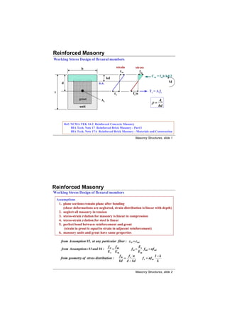
  • 1. Reinforced Masonry Working Stress Design of flexural members b strain stress εm fm Cm = fmb kd/2 kd d n.a. M Ts = Asfs t εs fs/n grout As As ρ= unit bd Ref: NCMA TEK 14-2 Reinforced Concrete Masonry BIA Tech. Note 17 Reinforced Brick Masonry - Part I BIA Tech. Note 17A Reinforced Brick Masonry - Materials and Construction Masonry Structures, slide 1 Reinforced Masonry Working Stress Design of flexural members Assumptions 1. plane sections remain plane after bending (shear deformations are neglected, strain distribution is linear with depth) 2. neglect all masonry in tension 3. stress-strain relation for masonry is linear in compression 4. stress-strain relation for steel is linear 5. perfect bond between reinforcement and grout (strain in grout is equal to strain in adjacent reinforcement) 6. masonry units and grout have same properties from Assumption #5, at any particular fiber : ε si = ε mi f si f mi Es from Assumption s #3 and #4 : = f si = f mi = nf mi E s Em Em fm f n 1− k from geometry of stress distribution : = s f s = nf m kd d − kd k Masonry Structures, slide 2
  • 2. Reinforced Masonry Working Stress Design of flexural members from equilibrium, C = T : f m bkd 1−k = As f s = ρ bd f s = ρ bd n f m 2 k 1− k k / 2= ρ n k 2 + 2 ρnk − 2 ρn = 0 k from equilibrium: ∑ M about C m = 0 M s = As f s jd = ρbd 2 jf s where jd=d-kd/3 or j=1-k/3 If fs=Fs then moment capacity will be limited by reinforcement. Allowable reinforcement tensile stress per MSJC Sec.2.3.2: Fs=20 ksi for Grades 40 or 50; Fs=24 ksi for Grade 60 Fs=30 ksi for wire joint reinforcement Allowable reinforcement tensile stress per UBC Sec.2107.2.11 : Fs= 0.5fy < 24 ksi for deformed bars; Fs= 0.5fy < 30 ksi for wire reinforcement Fs= 0.4fy < 20 ksi for ties, anchors, and smooth bars Masonry Structures, slide 3 Reinforced Masonry Working Stress Design of flexural members from equilibrium: ∑ M about T s =0 M m = 0.5 f m bkdjd = 0.5 f m jkbd 2 If fm= Fb then moment capacity will be limited by masonry. UBC 2107.2.6 & MSJC Sec.2.3.3.2: Fb=0.33f’m Masonry Structures, slide 4
  • 3. Reinforced Masonry WSD: Balanced Condition fm = F b Definition: The balanced condition occurs kbd C = fmb kd/2 when the extreme fiber stress in the masonry is equal to the allowable compressive stress, Fb, d and the tensile stress in the reinforcement is equal to the allowable tensile stress, Fs. T = As fs fs/n = Fs /n • For any section and materials, only one unique amount of balanced reinforcement exists. • Although balanced condition is purely hypothetical case, it is useful because it alerts the engineer to whether the reinforcement or the masonry stress will govern the design. Balanced stresses are not a design objective. Masonry Structures, slide 5 Reinforced Masonry WSD: Balanced Condition from geometry: from equilibrium: C=T Fs fm = Fb Fb + Fb n d = Fb b kb = ρb b d Fs kb d d 2 kbd Fk F n d Fb ρb = b b = b kb = 2 Fs 2 Fs ( n + Fs ) Fs Fb + Fb n fs/n = Fs /n n ⎡ n ⎤⎡ 1 ⎤ kb = ρb = ⎢ ⎥⎢ ⎥ n + Fs /Fb ⎣ n + Fs / Fb ⎦ ⎣ 2Fs / Fb ⎦ Masonry Structures, slide 6
  • 4. Example: Balanced Condition Determine the ratio of reinforcement that will result in a balanced condition per UBC. Given: f’m = 2000 psi and Grade 60 reinforcement Fb = 0.33 f'm = 667 psi Fs = 24 ksi for Grade 60 reinforcement E m = 750 f'm = 1500 ksi E s = 29,000 ksi E s 29,000 n = = = 19.3 Em 1500 ⎡ 19.3 ⎤⎡ 1 ⎤ ρb = ⎢ = 0.48% ⎣ 19.3 + 24/0.667 ⎥ ⎢ 2 x24/0.667 ⎥ ⎦⎣ ⎦ Masonry Structures, slide 7 Design Strategy for RM Flexural Design Procedure for sizing section and reinforcement for given moment. Calculate ρb knowing f’m and fy determine Fb from f’m determine Fs from fy determine Emfrom f’m determine n = Es/Em Size section for some ρ < ρb Note: Section must also be determine k and j sized for shear. bd2 = M/ρjFs select b and d using common units Size reinforcement Check design As = M/Fsjd Ms = AsFsjd > M select number and size of rebars fb = M/0.5jkbd2 < Fb Masonry Structures, slide 8
  • 5. Example: Reinforced Masonry Design a beam section for a moment equal to 370 kip-in. Prisms have been tested and f’m is specified at 2000 psi. Use Grade 60 reinforcement and 8” CMU’s. 1. From previous example, ρb = 0.48% 2. Estimate ρ to be slightly lower than ρ so steel will govern. b A good estimate is ρ = 0.4% 3. Solve for k : k 2 + 2 ρnk − 2 ρn = 0 2 ρn = 2( 0.004 )( 19.3 )= 0.154 k 2 + 0.154 k − 0.154 = 0 k = 0.323 j = 1 − k / 3 = 0.892 4. Solve for bd 2 : bd 2 = M / ρ j F s bd 2 = ( 370 kip − in ) /( 0.004 )( 0.892 )24 ksi ) = 4321 in 3 Masonry Structures, slide 9 Example: Reinforced Masonry 5. Select dimensions of beam using 8” CMU’s: b = 7.63” 4 - 8” CMU’s dreq’d = [4321 / 7.63]0.5 = 23.8” d=27.8” use four units and center bars in bottom unit, d = 27.8” 6. Estimate amount of reinforcem ent : As req' d = M / Fs j d 7.63” As req' d = (370 kip - in) / (24 ksi) (0.892) (27.8) = 0.62 in 2 use 2 #5' s (0.62 in 2 ) 7 . Check design: ρ = Αs / bd = 0.62 in 2 / (7.63quot; ) ( 27.8quot; ) = 0.00292 k 2 + 2 ρnk − 2 ρn = 0 k = 0.284 j = 1 − 0.284 / 3 = 0.905 Μ s = Αs Fs j d = ( 0.62 in 2 )( 24 ksi )( 0.905 )( 27.8quot; ) = 374 kip − in. > 370 kip − in. OK ( 370 kip − in x 1000 ) f m = Μ / 0. 5 j k d 2 = = 488 psi < 667 psi ok ( 0.5 )( 0.905 )( 0.284 )(7.63quot; )( 27.8quot; ) 2 Masonry Structures, slide 10
  • 6. Flexural Capacity of Partially Grouted Masonry Case A: neutral axis in flange * per MSJC Sec. 2.3.3.3 flange b = 6t or 72” or s* b tf kd neutral d t axis As As per width b If neutral axis is in flange, cracked section is the same as a solid rectangular section with width “b.” Therefore, depth to neutral axis from extreme compression fiber may be calculated using: As k 2 + 2 ρnk − 2 ρn = 0 ρ= bd If kd < tf assumption is valid, determine moment capacity as for rectangular section. If kd > tf assumption is not valid, need to consider web portion. Masonry Structures, slide 11 Shear Design of Reinforced Masonry s Cm Vm d Vs Vext. Viy Asfs Vd R Basic shear mechanisms: before cracking: Vext = Vint = Vm + Vd + Viy + Vs Once diagonal crack forms: • Vm reduces • flexural stresses increase • dowel action invoked • fsa is related to Mb Presence of shear reinforcement will: • restrict crack growth • resist tensile stress • help dowel action Masonry Structures, slide 12
  • 7. Shear Design of Reinforced Masonry after cracking: Vext = Vint = Vs = nAvfs where n is the number of transverse bars across the diagonal crack. Assuming a 45 degree slope, n=d/s Vs = (d/s)Avfs Av Vs Vs UBC Sec. 2107.2.17 (Eq. 7.38) = = MSJC Sec. 2.3.5.3 (Eq. 2-26) s df s dFs Masonry Structures, slide 13 Shear Design of Reinforced Masomry Flexural shear stress dx C M C + dC M + dM fvbdx na jd T T + dT T T + dT fvb dx = dT = dM/jd fv = (dM/dx)/bjd V fv = UBC Sec. 2107.2.17 (Eq. 7-38) bjd V fv = bd MSJC Sec. 2.3.5.2.1 (Eq. 2-19) Masonry Structures, slide 14
  • 8. Shear Design of Reinforced Masonry Allowable shear stresses for flexural members per UBC and MSJC UBC Sec. 2107.2.8.A and MSJC Sec. 2.3.5.2.2(a): members with no shear reinforcement Fv = 1.0 f'm < 50 psi UBC Eq. 7-17; MSJC Eq. 2-20 UBC Sec. 2107.2.8.B and MSJC Sec. 2.3.5.2.3(a): members with shear reinforcement designed to take the entire shear Fv = 3.0 f'm < 150 psi UBC Eq. 7-18; MSJC Eq. 2-23 Masonry Structures, slide 15 Shear Design of Reinforced Masonry Allowable shear stresses for shear walls per UBC and MSJC UBC Sec. 2107.2.9.i and MSJC Sec. 2.3.5.2.2(b): walls with in-plane flexural reinforcement and no shear reinforcement M 1 M M for <1 F v = ( 4 − ) f 'm <( 80 − 45 ) psi UBC Eq. 7-19; MSJC Eq. 2-21 Vd 3 Vd Vd M for ≥1 F v = 1.0 f 'm < 35 psi UBC Eq. 7-20; MSJC Eq. 2-22 Vd UBC Sec. 2107.2.9.ii and MSJC Sec. 2.3.5.2.3(b): walls with in-plane flexural reinforcement and shear reinforcement designed to take 100% of shear M 1 M M for <1 Fv = ( 4 − ) f'm < ( 120 − 45 )psi UBC Eq. 7-21; MSJC Eq. 2-24 Vd 2 Vd Vd M for ≥1 F v = 1.5 f 'm < 75 psi h UBC Eq. 7-22; MSJC Eq. 2-25 Vd Masonry Structures, slide 16
  • 9. Shear Design of Reinforced Masonry Moment-to-Shear Ratios For a single-story For piers between openings cantilevered shear walls M d V V d h h M M M Vh h M Vh / 2 h = = = = Vd Vd d Vd Vd 2d Masonry Structures, slide 17 Shear Design of Reinforced Masonry Additional MSJC Requirements MSJC Sec. 2.3.5.3.1 smax = d/2 or 48” MSJC Sec. 2.3.3.4.2 minimum reinforcement perpendicular to shear reinforcement = Av/3 smax = 8 ft MSJC Sec. 2.3.5.5 design for shear force at distance “d/2” out from support Vdesign Vdesign d/2 Masonry Structures, slide 18
  • 10. Shear Design of Reinforced Masonry Shear Design Strategy for Reinforced Sections Start Determine Flexural Tension Stress Determine Fv Assuming Shear ft= -P/A+Mc/I Reinforcement to take 100% of Shear consider as no no is ft>Ft? Resize unreinforced is fv<Fv? Section yes yes Determine Maximum Design Shear Provide Reinforcement to Take 100% of Shear Determine Shear Stress Av V V V = s fv = or s dFs bjd bd no yes Determine Fv Assuming No Shear is fv<Fv? End Reinforcement Masonry Structures, slide 19 Example: Design of RM Shear Wall Determine the maximum lateral force, Hwind per UBC and MSJC 6’-8” 8” CMU wall 120 psi Type S - PCL mortar solidly grouted f’m=3000 psi #4 @ 32” 2 - #8’s each end of wall 8’-0” Case A: neglect all reinforcement Case B: consider vertical reinf., neglect horizontal reinf. Case C: consider vertical and horizontal reinf. 6’-4” Case D: design horizontal reinforcement for max. shear Masonry Structures, slide 20
  • 11. Example: Design of RM Shear Wall Case A: neglect all reinforcement per UBC: 7.63 × 80 2 Sg = = 8139 in3 flexure 6 M 96 × H - fa + = Ft − 120 + = 40 x 1.33 H = 14 ,684 lbs. = 14.7 kips S 8139 shear Fv = [ 34 psi + 0.2 fa dead ] x 1.33 = [ 34 + 0.2 ( 120 )] x 1.33 = 77.1 psi 77.1 psi Vmax = Ae Fv = ( 7.63 x 80.0 )( ) = 47.1 kips 1000 per MSJC: flexure 96 × H - fa + M / S = Ft − 120 + =0 H = 10 ,174 lbs . = 10.2 kips shear 8139 Fv = 60 + 0.45 ( 120 ) = 114 psi > 1.5 f'm = 82.2 psi Fv = 1.33 × 82.2 psi = 109 psi 2 2 Vmax = Fv bt = ( 109 psi )( 7.63 x 80 ) = 44.3 kips 3 3 Masonry Structures, slide 21 Example: Design of RM Shear Wall Case B: consider only vertical reinforcement Flexure by UBC or MSJC: neglecting fa Ms = AsFsjd = 2 x 0.79 in2 (1.33 x 24 ksi) (0.9 x 72.0”) = 3268 k-in Hwind = 34.0 kips lumping 2 - #8’s ave. d for 2 bars Shear per UBC Sec.2107.2.9 or MSJC Sec.2.3.5.2 8.0' M/Vd = = 1.33 > 1 6.0' M for > 1 Fv = 1.0 f 'm < 35 psi Fv = 1.33 x 35 psi = 46.6 psi Vd for UBC Vmax = bjdFv = ( 7.63quot; )( 0.9 )( 72quot; )( 46.6 psi ) / 1000 = 23.0 kips governs for MSJC Vmax = bdFv = ( 7.63quot; )( 72quot; )( 46.6 psi ) / 1000 = 25.6 kips governs Masonry Structures, slide 22
  • 12. Example: Design of RM Shear Wall Case C: consider all reinforcement Flexure by UBC or MSJC: same as case B Shear per UBC Sec. 2107.2.17 or MSJC Sec.2.3.5.3 Vmax= Vs=(Av/s)Fsd = (0.20 in2/32”)(24 ksi x 1.33)(72”) = 14.4 kips governs Overall shear per UBC Sec. 2107.2.9.C or MSJC Sec. 2.3.5.2.3 (b) M for > 1 F = 1.5 f'm ≤75 psi F = 1.5 3000 = 82.2psi>75 psi v v Vd Fv = 1.33x 75 psi= 100 psi V (14.4 kips x 1000) UBC f v = = = 30.7 psi < 100 psi okay bjd (7.63)( 0 .9 )(72) V (14.4 kips x 1000) MSJC f v = = = 27.7 psi < 100 psi okay bd (7.63)(72) Masonry Structures, slide 23 Example: Design of RM Shear Wall Case D: design horizontal reinforcement for maximum shear strength Vmax = Fvbjd = ( 100 psi)( .63)(0.9 )(72)/ 1000 = 49.4 kips > 34 kips oka govern 7 y s Av /S = Vmax/Fsd = 49.4 kips/( .33 x 24 ksi)( ) = 0.0215in2 per in. 1 72 u sing #4 rebars(Av = 0.20 in2 ) s = 0.20 / 0.0215 = 9.3quot; use # @ 8 in. horiz 4 ontal Summary: Hmax, kips Case Consideration UBC MSJC A No steel No steel 14.7* 14.7* 10.2* 10.2* vertical steel 24.3 27.0 B vertical steel 23.0 25.6 no horizontal steel no horizontal steel vertical steel and 15.2 15.2 C vertical steel and 14.4 14.4 #4 @ 32” horizontal steel #4 @ 32” horizontal steel D #4#4 @ 8” horizontal @ 8” horizontal 34.0* 34.0* 34.0* *flexure governs Masonry Structures, slide 24
  • 13. Flexural Bond Stress M = Tjd M + dM = (T + dT)jd dM = dT jd dx dT = dM/jd C + dC U = bond force per unit length for group of bars C U dx = dT = dM/jd U = (dM/dx)/jd = V/jd M U dx jd u = flexural bond stress = M + dM ∑o where ∑ o = sum of perimeters of all bars in group T T + dT V u= UBC Sec. 2107.2.16 Eq. 7-36 dx Σ ο jd U T + dT allowable bond stress per UBC Sec.2107.2.2.4: T 60 psi for plain bars 200 psi for deformed bars dx 100 psi for deformed bars w/o inspection Masonry Structures, slide 25 Development Length uπ d b db As fs ld As fs = uπdb ld πd b 2 fs = uπdb ld 4 f s db ld = = 0.002 db fs for u = 125 psi UBC Sec. 2107.2.2.3 Eq.7 - 9 4u ld = 0.0015 db Fs for u = 167 psi MSJC Sec . 2.1.8.2 Eq . 2 − 8 Masonry Structures, slide 26
  • 14. Embedment of Flexural Reinforcement UBC Sec. 2106.3.4 and MSJC Sec.2.1. 8.3 Rule #1: extend bars a distance of “d” or “12db” past the theoretical cutoff point Rule #2: extend bars a distance of “ld” past the point of maximum stress Example for shear wall: bars “a” Moment Diagram (#2) > ld (#1) d or 12db theoretical cutoff point capacity with bars “a” bars “b” (#2) > ld moment capacity with bars “a” and “b” Masonry Structures, slide 27 Combined Bending and Axial Loads Code Requirements UBC Sec. 2107.1.6.3 fa fb use unity formula to check compressive stress: + < 1.0 Fa Fb UBC Sec. 2107.1.6.1 UBC Sec. 2107.2.15 P M Note: unity formula is conservative - better approach is to use P-M interaction diagram. M As fs fb = ( Eq .7 − 31 ) 2 jkbd 2 fa = P/Ae kd jd UBC Sec. 2.14.2 if h’/t >30 then analysis should consider effects of deflections on moments MSJC Sec. 2.3.3.2.2 fa + fb < 1/3 f’m provided that fa < Fa In lieu of approximate method, use an axial-force moment interaction diagram. Masonry Structures, slide 28
  • 15. Axial Force-Moment Interaction Diagrams General Assumptions 1. plane sections remain plane after bending • shear deformations neglected • strain distribution linear with depth 2. neglect all masonry in tension 3. neglect steel in compression unless tied Strain Stress 4. stress-strain relation for masonry is linear in compression εm fm 5. stress-strain relation for steel is linear 6. perfect bond between reinforcement and grout Cs • strain in grout is equal to strain in adjacent reinforcement 7. grout properties same as masonry unit properties P M εs Ts=Asfs Masonry Structures, slide 29 Axial Force-Moment Interaction Diagram Out-of-Plane Bending of Reinforced Wall Pa Mb d = t/2 Range “a”: large P, small M, e=M/P < t/6 unit width = b Pa = 0.5(fm1 + fm2)A Ma= 0.5(fm1 - fm2)S where S = bt2/6 fm2 fm1 em Cm Masonry Structures, slide 30
  • 16. Axial Force-Moment Interaction Diagram Out-of-Plane Bending of Reinforced Wall Pb Mb d = t/2 Range “b” medium P, medium M, e > t/6, As in compression unit width = b 0.5 < α < 1.0 for section with reinforcement at center t αt em = − 2 3 fm 1 fm1 Pb = C m = αtb em 2 Cm M b = C m em αt Masonry Structures, slide 31 Axial Force-Moment Interaction Diagram Out-of-Plane Bending of Reinforced Wall Pc Mc Range “c” small P, large M, e > t/6, As in tension d = t/2 α < 0.5 for section with reinforcement at center unit width = b t αt em = − 2 3 fm 1 Pc = C m − Ts Cm = αtb Ts = As fs 2 f s ⎡ d − αt ⎤ ⎡ 0. 5 − α ⎤ t = fm 1 = ⎢ f for d = fm1 n ⎢ αt ⎥ ⎣ ⎦ ⎣ α ⎥ m1 ⎦ 2 em Ts Cm t M c = C m em + Ts ( d − ) αt 2 Masonry Structures, slide 32
  • 17. Axial Force-Moment Interaction Diagram Out-of-Plane Bending of Reinforced Wall Range “a” Range “b” Range “c” e=0; M=0 fm1= fm2=Fa fm1= Fb= f’m/3 P=Fa A Reduce fm2 from Reduce α from Reduce α from 2Fa-Fb by 1.0 by 0.5 by Start increment increment increment compression controlling Determine P & M Determine P and Determine P and tension controlling per Range “a” M per Range “b” M per Range “c” no yes no is As in yes yes fm2 = 0? tension? M = 0? no no yes fs = Fs fs < Fs? fs < Fs fm1 < Fb fm1 = Fb Stop Masonry Structures, slide 33 Axial Force-Moment Interaction Diagram Out-of-Plane Bending of Reinforced Wall fm1 = Fb Fb fm1 = Fa fm2 = 2Fa - Fb Fa Fb Range “a” lim it b yu Axial Force Fb Range “b” nit 1 y for tension compression e mu fs/n controls controls Fs/n la Fb Fb balanced point Range “c” Fs Fs/n Moment fs = fm Masonry Structures, slide 34
  • 18. Example: Interaction Diagram Determine an axial force-moment interaction diagram for a fully grouted 8” block wall reinforced with #4 @ 16”. Prism compressive strength has been determined by test to be equal to 2500 psi. Reinforcement is Grade 60. Height of wall is 11.5 feet. Fs = 24 ksi for Grade 60 Fa = 0.25 f´ m = 625 psi without reduction factor Fb = 0.33f´ m = 833 psi E m = 750 f´ m = 1875 ksi per UBC E s = 29,000 ksi n = E s /E m = 15.5 per foot of wall : Ag = 7.63quot; x 12quot; = 91.6 in 2 ; S g = 12quot; x 7.63 2 / 6 = 116 in 3 As / ft = 0.20 x 12 / 16 = 0.150 in 2 ρ = 0.20 in 2 /( 16 x 3.81quot; ) = 0.0033 ρn = 0.0509 k = 0.272 j = 0.909 Masonry Structures, slide 35 Example: Interaction Diagram Fs ⎛ α ⎞ *masonry stress inferred from Fs and α: f m 1 = ⎜ ⎟ n ⎝ 0.5 − α ⎠ Range Case fm1 fm2 α Cm em Ts P=Cm- Ts M=Cm em (psi) (psi) (kips) (in.) (kips) (kips) (kip-in) 1 625 625 - 57.2 0 - 57.2 0 Compression Controls a 2 833 417 - 57.2 - - 57.2 24.1 3 833 0 - 38.1 1.27 - 38.1 48.4 4 833 - 0.75 28.6 1.91 - 28.6 54.5 b 5 833 - 0.50 19.1 2.54 - 19.1 48.5 6 833 - 0.33 12.6 2.97 0.9 11.7 37.4 7 833 - 0.25 9.5 3.18 2.0 7.5 30.2 8 833 - 0.167 6.4 3.39 3.9 2.5 21.5 9 for P = 0: Mm= 0.5Fbjkbd2 = 0.5(833 psi)(0.909)(0.272)(12)(3.81)2 = 17.9 c Controls 10 833 bal. - 0.175 6.7 3.37 3.6 3.1 22.5 Tension 11 664* - 0.150 4.6 3.43 3.6 1.0 15.7 12 check for P = 0: Ms = AsFsjd = (0.15 in2)(24 ksi)(0.909)(3.81”) = 12.5 Masonry Structures, slide 36
  • 19. Example: Interaction Diagram 50 1 2 6 833 0.9k 1 625 0.33t 40 2.0 k 2 833 7 833 Axial Force 3 417 0.25t kips 30 4 0 3 833 8 833 3.9 k > AsFs 20 5 0.167t 4 833 10 833 6 .75t 3.6 k = AsFs 10 10 0.175t 11 7 12 5 833 11 664 3.6 k = AsFs 10 20 30 40 50 0.15t 8 0.50t 9 Moment, kip-in Masonry Structures, slide 37 Flexural Capacity with Axial Compression Short Cut Method Out-of-Plane Bending, Reinforcement at Center fm d kd Cm d jd M Ts P fs/n f s /n f k f E stress compatibility: = m ; fm = ( s ) where n = s [1] d - kd kd 1-k n Em C m = 0.5 f m bkd [2] Ts = As f s = ρbdf s [3] Masonry Structures, slide 38
  • 20. Flexural Capacity with Axial Compression Short Cut Method P = C m - Ts [4] equilibrium: P = 0.5 f m bkd - ρbdf s [5] f ⎛ k ⎞ P = 0.5 ( s )⎜ ⎟ bkd - ρbdf s [6] n ⎝1-k ⎠ P k2 ⎛ 1 ⎞ = 0 .5 ⎜ ⎟− ρ [7] bdf s 1− k ⎝ n⎠ P if tension controls , f s = Fs set α = [8] bdFs 2 k ⎛ 1⎞ a = 0.5 ⎜ ⎟− ρ [9] (1 − k) ⎝ n ⎠ 1 k2 ρ +α = [10] 2n 1 − k k 2 + 2 n( ρ + α )k − 2 n( ρ + α ) = 0 [11] M = C m jd = 0.5 f m bkjd 2 where j = 1 − k / 3 [12] Masonry Structures, slide 39 Strength Design of Reinforced Masonry Ultimate Flexural Strength strains stresses As ε mu Cm c d n.a. t d Mn b εs > εy Ts = Asfy k3f’m k3f’m fm f’m k2c k2c c klc Cm = c Cm = k1k3f’mbc εm εmu Note: rectangular stress block can represent compressive stress distribution if k2/k1 = 0.5 Masonry Structures, slide 40
  • 21. Strength Design of Reinforced Masonry Measuring k1k3 and k2 Po P1 Po in displacement control P1 in force control summing moments about centroid: a increase P1 P1a = (Po + P1)g so that ∆ = 0 = (Po + P1)(c/2 - k2c) ∆ P1 a k 2 = 0.5 - c Po + P1 c strain g total compressive force: stress Po + P1 = k3f’m k1cb P0+P1 Po + P1 k2c k1 k 3 = f 'm bc k3f’m k1c Masonry Structures, slide 41 Strength Design of Reinforced Masonry Measured k1k3 and k2 values Sample experimentally determined constants k1k3, and k2 1 0.8 K1K3 K1K3 & K2 0.6 0.4 K2 0.2 0 0 0.001 0.002 0.003 0.004 0.005 0.006 Extreme Fiber Strain (in/in) Masonry Structures, slide 42
  • 22. Strength Design of Reinforced Masonry Ultimate Flexural Strength equilibrium C m + Ts = 0 k1 k 3 f 'm bc = As f y = ρbd f y fs ρdf y fy c = k1 k 3 f 'm summing moments about Cm εs M n = As f y ( d − k 2 c ) ρ df y M n = As f y ( d − k 2 ) k 1 k 3 f 'm ρf y M n = As f y d ( 1 − k 2 ) k 1 k 3 f 'm k2 fy if = 0.5 and k 3 = 0.85 then : M n = As f y d ( 1 − 0.59 ρ ) k1 f 'm Masonry Structures, slide 43 Strength Design of Reinforced Masonry Balanced condition with single layer of reinforcement strains stresses strain compatibility ε mu c ε mu ε mu = or c = d ε mu + ε y d ε mu + ε y k1c Cm c equilibrium n.a. C m + Ts = 0 d Mn ε mu k1 k 3 f 'm b d = ρ b bdf y ε mu + ε y k1 k 3 f 'm ε mu ρb = εs = ε y Ts= Asfy fy ε mu + ε y fy if k 3 = 0.85 ε mu = 0.003 ε y = E s = 29 ,000 ,000 psi : Es k1 ( 0.85 ) f 'm 0.003 0.85 k1 f 'm 87 ,000 ρb = = fy 0.003 + f y / E s fy 87 ,000 + f y Masonry Structures, slide 44
  • 23. Strength Design of Reinforced Masonry Balanced condition with single layer of reinforcement 0.85 k1 f 'm 87 ,000 ρb = ρ tb = As / bt for one layer of steel t = 2d k 1 = 0.85 fy 87 ,000 + f y Grade 40 Grade 60 f’m ρb ρ tb ρb ρ tb 1000 0.0124 0.0062 0.0071 0.0036 2000 0.0247 0.0124 0.0143 0.0072 3000 0.0371 0.0186 0.0214 0.0107 4000 0.0495 0.0247 0.0285 0.0142 5000 0.0619 0.0309 0.0356 0.0178 6000 0.0742 0.0371 0.0428 0.0214 Masonry Structures, slide 45 Strength Design of Reinforced Masonry Balanced condition with multiple layers of reinforcement strains stresses b ε mu 0.85f’m d1 ε s1 Cs1 d2 0.85c ε s2 Cm=0.85f’mb(0.85c) Cs2 c d3 d4 ε s3 Ts3 Ts4 = Asbal fy ε s4 = ε y Asbal strain compatibility equilibrium d ε mu f si = E sε si < f y ε si < ε mu − ( i )( ε mu + ε sy ) c= d d4 ε mu + ε y C si or Tsi = Asbal i f si 60 ksi C m + ∑( C si + Tsi ) = 0 εy= = 0 .00207 (Grade 60) 29,000 ksi − 0.428 f 'm bd + Asbal ∑ f si = 0 if ε mu = 0.003 , then c = 0 .592 d solve for Asbal Masonry Structures, slide 46
  • 24. Example: Flexural Strength of In-Plane Wall Determine the maximum bar size that can be placed as shown. Maximum steel is equal to one-half of that resulting in balanced conditions. f’m= 1500 psi Grade 60 reinforcement special inspection 7.63” 0.003 0.85f’m ε s1 4.0” Cs1 20.0” Cm = 0.85f’mb(0.85c) εs 2 44.0” c 60.0” Cs2 5’-4” Pn = 0 n.a. εs 3 Ts3 Asbal ? Ts4 = Asbal fy ε s = ε y = 0 .00207 Masonry Structures, slide 47 Example: Flexural Strength of In-Plane Wall Determine the maximum bar size. c = 0.003/0.00507 (60.0”) = 35.5” Cm = 0.85f’mb(0.85c) = -0.85(1500)(7.63”)(0.85 x 35.5) = -294 k layer di εsi fsi ⎛ c − d1 ⎞ εi =⎜ ⎟ ( −0.003 ) ⎝ c ⎠ 1 4.0” -0.00261 (C) -60.0 2 20.0” -0.00131 (C) -38.0 f si = E sε si ≤ f y 3 44.0” 0.00072 (T) 20.8 4 60.0” 0.00207 (T) 60.0 without compression steel (neglect Cs1 andCs2 forces) Cm + Σ(Csi + Tsi) = -294 + Asbal (20.8+ 60.0) = 0 Asbal = 3.64 in2 Asmax = 1.82 in2 max. bar size is #ll (1.56 in2)* *bars larger than #9 are not recommended because of anchorage and detailing problems with compression steel (include Cs1 and Cs2 forces) Cm + Σ(Csi + Tsi) = -294 + Asbal (-60.0 - 38.0 + 20.8 + 60.0) = 0 Asbal = -17.1 in2 note: negative Asbal means that ΣC > ΣT , in such case no limit on tensile reinforcement Masonry Structures, slide 48
  • 25. Example: Flexural Strength of In-Plane Wall Determine flexural strength of wall. f’m= 1500 psi Grade 60 reinforcement special inspection 0.003 0.85f’m ε s1 Cs1 4.0” 20.0” c Cm = 0.85f’mb(0.85c) 44.0” n.a. Ts2 60.0” εs 2 5’-4” εs 3 Ts3 εs > ε y Ts4 = As fy #8 (typ) = 0.79 in2 x 60 ksi = 47.4 k 7.63” Masonry Structures, slide 49 Example: Flexural Strength of In-Plane Wall Determine flexural strength of wall. ⎛ c − di ⎞ εi =⎜ ⎟( −0.003) compressive strains = (-) fsi = Esεsi < f y Cm =8.27c ⎝ c ⎠ d1 = 4.0” d2 = 20.0” d3 = 44.0” c ε1 f1 Csl ε2 f2 Ts2 ε3 f3 Ts3 Cm ∑(C + T ) 0.00360 60.0 20.0 -0.00240 -60 -47.4 0 0 0 -165 -117.6 47.4 15.0 -0.00220 -60 -47.4 0.00100 29.0 22.9 0.00580 60.0 47.4 -124 -54 11.0 -0.00191 -55 -43.7 0.00245 60.0 47.4 0.00900 60.0 47.4 -91 +7.5 11.5 -0.00196 -56 -44.8 0.00222 60.0 47.4 0.00848 60.0 47.4 -95 +2.3 0.85 c close to zero, take c = 11.5” M n = ∑ { Asi f si ( d i − )} 2 = ( −44.8 )( 4.00 − 4.89 ) + ( 47.4 )( 20.0 − 4.89 ) + ( 47.4 )( 44.0 − 4.89 ) + ( 47.4 )( 60.0 − 4.89 ) = 5 ,222 kip − in Masonry Structures, slide 50
  • 26. Example: Flexural Strength of In-Plane Wall Approximate flexural strength of wall. neglecting C sl and Ts 2 , and lumping As 3 and As 4 ( 60 + 44 ) 2 × 0.79 d= = 52.0quot; ρ= = 0.00398 2 7.63 × 52 fy 5’-4” M n = As f y d ( 1 − 0.59 ρ ) f 'm 60 = 2( 0.79 in 2 )( 60 )( 52.0 )( 1 − 0.59 x 0.00398 x ) 1.50 = 4 ,467 kip − in 86% of answer #8 (typ) 7.63” Masonry Structures, slide 51 Slender Wall Design Limitations of Method: UBC Sec. 2108.2.4 (a) for out-of-plane bending of solid, reinforced walls lightly stressed under gravity loads (b) limited to: Pw + Pf ≤ 0.04 f'm ( 8 − 19 ) Sec. 8.2.4.4 210 where f'm <6000 psi Ag Pw + Pf h' Note : when 0.04f'm < < 0.20f'm , method still can be used providing that < 30 Ag t (c) ρg= As/bt < 0.5 ρbal (d) special inspection must be provided during construction (e) t > 6” Sec. 2108.1.3: Load factors U = 1.4 D + 1.7 L U = 0.9 D ± 1.4 E U = 1.4( D + L + E ) U = 0.9 D ± 1.3W U = 0.75( 1.4 D + 1.7 L + 1.7W ) Ref: NCMA TEK 14-11A Strength Design of Tall Concrete Masonry Walls Masonry Structures, slide 52
  • 27. Slender Wall Design Required Flexural Strength: UBC Sec. 2108.2.4.4 e eccentric transverse P∆ load load Puf Pufe t h/2 Puw wu h wuh2/8 (Puw + Puf)∆ u Pufe/2 h/2 Pu = Puf + Puw wu h2 Puf e Mu = + + ( Puw + Puf )∆u ( 8 − 20 ) 8 2 Masonry Structures, slide 53 Slender Wall Design Design Considerations Design strength: Sec. 2108.2.4.4 Mu < φ Mn (8 - 22) Strength reduction factor: flexure φ = 0.8 Sec. 2108.1.4.2.1 Assumptions for ultimate flexural strength (Sec. 2108.2.1.2) 1. equilibrium 2. strain compatibility 3. εmu = 0.003 4. fs = Esεs < fy 5. neglect masonry strength in tension 6. rectangular stress block, k1 = 0.85, k3 = 0.85 Masonry Structures, slide 54
  • 28. Slender Wall Design Equivalent area of reinforcement, Ae for single wythe construction reinforced at center: d As a = 0.85c b 0.85f’m Ts = Asfy d c Pu Cm =0.85f’mb(0.85c) Ts = Asfy Pu = Cm - Asfy Cm Cm = Pu + Asfy= Asefy ( Pu + As f y ) Pu Ase = Eq. (8-24) fy flexural strength a ( Pu + As f y ) M n = Ase f y ( d − ) Eq. (8 - 23) where a = Eq. (8 - 25) 2 0.85 f 'm b Masonry Structures, slide 55 Slender Wall Design Lateral Deflections 5 wh 4 5 wh 2 h 2 5 Mh 2 ∆= = = M 384 EI 48 8 EI 48 EI 5 M s h2 for Ms < Mcr ∆s = (8-28) My 48 E m I g ∆y 5 M cr h 2 5 ( M s − M cr )h 2 Ms for Ms > Mcr ∆s = + (8-29) 48 E m I g 48 E m I cr ∆s Mcr b( kd )3 where I cr = nAse ( d − kd )2 + ∆cr 3 Mcr = fr S ∆ (note “kd” may be replaced by “c” for simplicity) Modulus of Rupture, fr Eqs. 8-31, 32, 33 fully grouted partially grouted hollow unit 4.0 f'm < 235 psi 2.5 f 'm < 125 psi 2-wythe brick 2.5 f 'm < 125 psi not allowed Masonry Structures, slide 56
  • 29. Slender Wall Design Design Considerations Serviceability Criteria ∆s ≤ 0.007 h ( 8 − 27 ) Strength Criteria w h 2 Puf e Mu = u + + ( Puw + Puf )∆u 8 2 5 M cr h2 5 ( M u − M cr )h2 ∆u = + 48 E m I g 48 E m I cr Masonry Structures, slide 57 Example: Slender Wall Design Determine the maximum wind load, w, per UBC and MSJC 3.5” 500 lbs/ft dead 200 lbs/ft live 3’-0” P w 8” CMU, partially grouted f’m = 2000 psi, Grade 60 7 .63quot; e = 3 .50quot; + = 7 .31quot; 2 12quot; in 2 As = 0 .20 in 2( ) = 0 .075 32quot; ft 20’-0” #4 @ 32” As 0 .075 1 1 ρ = = = 0 .000164 < ρbal = ( 0.0143)=0.0072 ok bd 12× 3.81 2 2 Masonry Structures, slide 58
  • 30. Example: Slender Wall Design Flexural Strength per UBC U = 0.75 (1.4D + 1.7L + 1.7W) w h 2 Puf e a Mu = u + + ( Puw + Puf )∆u < φ M n = φ Ase f y ( d − ) 8 2 2 Pu = Puf + Puw Puf = 0.75 ( 1.4 x 500 + 1.7 x 200 ) = 780 lbs . Puw = 0.75 ( 1.4 x 64 psf x 13' ) = 874 lbs . Pu = 1654 lbs . ( Pu + As f y ) ( 1.65 kips + 0.075 x 60 ksi ) Ase = = = 0.103 in 2 fy 60 ksi ( Pu + As f y ) 0.103 ( 60 ) a= = = 0.302quot; 0.85 f 'm b ( 0.85 x 2.0 ksi x 12quot; ) 0.302quot; c= = 0.355quot; < 1.2quot; neutral axis within face shell, treat as rectangular section 0.85 Mu=φMn = φAsefy(d - a/2)=0.8(0.103in2)(60ksi)(3.81in - 0.302in/2)=18.1 kip-in Masonry Structures, slide 59 Example: Slender Wall Design Flexural Strength per UBC Es 29,000 Em =750 f 'm = 1500ksi n= = = 19.3 Em 1500 Icr = nAse ( d − c )2 + bc3 3 ( ) = 19.3 0.103in2 ( 3.81− 0.355 )2 + 12( 0.355 )3 3 quot; = 23.9 in4 2 2 5 Mcrh 5 ( Mu − Mcr )h ∆u = + 48 Em I g 48 Em Icr 12quot; x7.632 Mcr = fr Sg fr = 2.5( f 'm )0.5 = 112 psi Mcr = 0.112ksi ( ) = 13.1 k − in. 6 for simplicity, use gross section even though partially grouted to avoid iteration, assume Mmax = Mu 5 ( 13.1 )( 20 x 12 )2 5 ( 18.1− 13.1 )( 20 x 12 )2 ∆u = + = 0.118 + 0.837quot; = 0.955 quot; quot; 48 ( 1500)( 444 ) 48 ( 1500)( 23.9 ) w ( 20 )2 0.780 7.31 / 2 ) ' ( quot; 0.955 Mu = u + +( 1.654)( )=181k − in. / 12 . quot; 8 12 12 wu ws = = 17.8psf wu=22.7 psf 0.75x1.7 Masonry Structures, slide 60
  • 31. Example: Slender Wall Design Check Service Load Deflections per UBC ∆s < 0.007 h 5 M cr h 2 5 ( M s − M cr )h 2 ∆s = + 48 E m I g 48 E m I cr w s h2 Ms = + Po e / 2 + ( Pw + Po ) ∆s 8 ⎡ ( 17.8 psf )( 20 )2 ⎤ 700 ( 7.31quot; ) =⎢ ⎥ x 12 + + 1532 ∆s = 13 ,239 + 1532 ∆s ( lb . − in .) ⎢ ⎣ 8 ⎥ ⎦ 2 5 ( 13.239 + 1.532 ∆s − 13.1 )( 20 x 12 )2 ∆s = 0.118quot; + 48 ( 1 ,500 )( 23.9 ) ∆s = 0.19quot; < 0.007 h = 0.007 (20' x 12 ) = 1.68quot; ok ) Masonry Structures, slide 61 Example: Slender Wall Design Maximum Wind Load per MSJC d = 3.82” 1.25” w h2 P e M s = s + os + ( Pws + Pos )∆s 8 2 #4 @ 32” w s ( 20' )2 = x 12 + 700 lbs ( 3.66quot; ) + ( 1532 lbs ) ∆s 8 = 600 w s + 2562 lb − in . + 1532 ∆s Determine Icr considering axial compression k 2 + 2 n( ρ + α )k − 2 n( ρ + α ) = 0 0.075 in 2 P 1.532 k n = 19.3 ρ= = 0.00164 α= = = 0.00104 12quot;×3.82quot; bdFs 12quot; × 3 .82quot; × 32 ksi k 2 + 0.0104 k − 0.0104 = 0 k = 0.275 kd = 1.05quot; < face shell thickness, ok k j = 1 − = 0.908 jd = 3.47quot; 3 b( kd )3 12quot; ( 1.05quot; )3 I cr = + nAs ( d − kd )2 = + 19.3( 0.075 in 2 )( 3.82quot; −1.05quot; )2 = 15.7 in 4 3 3 Masonry Structures, slide 62
  • 32. Example: Slender Wall Design Maximum Wind Load per MSJC M s = As Fs + ( Pws + Pos ) jd = [( 0.075 × 32 ksi) + 1.532 ] 3.47quot; = 13.64 kip - in 0.600 w s + 2.56 kip - in . + 1.532 ∆s = 13.64 kip - in w s = 18.47 − 2.55 ∆s ( w s is in psf) 2 5 M cr h 5 ( M s − M cr )h 2 ∆s = + 48 E m I g 48 E m I cr 5 ( 0.600 w s + 2.56 kip - in . + 1.532 ∆s − 13.1 )( 20 × 12 )2 ∆s = 0.118quot; + 48 ( 1500 ksi)(15.7 in 4 ) ∆s = 0.118quot; +0.153 w s + 0.652 + 0.390 ∆s − 3.34 ∆s = 0.251 w s − 4.21 w s = 18.47 − 2.55 ∆s ( 0.251 w s − 4.21 ) w s = 17.8 psf Note: same wind load as by UBC slender wall design procedure. Should also check compressive stress with an axial force-moment interaction diagram Masonry Structures, slide 63 Strength Design of RM Shear Walls UBC Requirements UBC Sec. 2108.1.1: Strength procedure may be used as an alternative to Sec. 2107 for design of reinforced hollow-unit masonry walls. UBC Sec. 2108.1.2: Special inspection must be provided during construction. Prisms should be tested or unit strength method should be used. UBC Sec.2108.1.3: Shear wall design procedure 1. Required strength A. earthquake loading: U = 1.4 (D+L+E) (12-1) U = 0.9D + - 1.4E (12-2) B. gravity loading: U = 1.4D + 1.7E (12-3) C. wind loading: U = 0.75(1.4D + 1.7 L + 1.7W) (12-4) U = 0.9D + - 1.3W (12-5) D. earth pressure: U = 1.4D + 1.7L + 1.7H (12-6) 2. Design strength φ = 0.65 for φPn > 0.1 f 'm Ae or φPn > 0.25 Pb (see next slide) A. axial load and flexure φ = 0.85 for φPn = 0 B. shear φ = 0 .60 for shear limit state φ = 0.80 for flexure limit state Masonry Structures, slide 64
  • 33. Strength Design of RM Shear Walls Definition of Balanced Axial Load, Pb ε mu 0.85f’m Cs1 a b = 0.85 c Cm = 0.85f’mbab c Cs2 Lw d Pb n.a. Ts3 Ts4 = Asbalfy ε s = ε y = 0.00207 b assume ΣC si = ΣTsi so Pb = C m emu for solidly grouted walls : Pb = 0.85 f 'm bab where ab = 0.85 d fy ( emu + ) Es Masonry Structures, slide 65 Strength Design of RM Shear Walls UBC Requirements 3. Design assumptions (same as for Slender Wall Design Procedure, UBC Sec. 2108.2.1.2) 1. equilibrium 2. strain compatibility 3. εmu = 0.003 4. fs = Esεs < fy 5. neglect masonry tensile strength 6. use rectangular stress block, k1 = 0.85, k3 = 0.85 7. 1500 psi < f’m < 4000 psi Masonry Structures, slide 66
  • 34. Strength Design of RM Shear Walls UBC Requirements 4. Reinforcement per UBC Sec. 2108.2.5.2 Mn > Mcr 1. minimum reinforcement M ductile ρ v + ρ h ≥ 0.002 ρ v and ρ h ≥ 0.0007 Mcr spacing ≤ 4' −0quot; Mn < Mcr nonductile 2. for flexural failure mode Mn > = 1.8 Mcr for fully grouted wall ∆ Mn > = 3.0 Mcr for partially grouted wall 3. anchor all continuous reinforcement 4. As vertical > 1/2 As horizontal 5. maximum spacing of horizontal reinforcement within plastic hinge region = 3t or 24” 5. Axial strength (no flexure) Po = 0.85 f’m(Ac-As) + fyAs Pu < = φ (0.80)Po Masonry Structures, slide 67 Strength Design of RM Shear Walls UBC Requirements 6. Shear Strength UBC Sec. 2108.2.5.5 1. maximum nominal shear: M Vn = 6.0 Ae f 'm ≤ 380 Ae for ≤ 0.25 Vd M = 4.0 Ae f 'm ≤ 250 Ae for ≥ 1.0 (Table 21 - J ) Vd Amv t 2. for walls limited by shear strength: Lw Vn = Vm + Vs where Vm = C d Amv f 'm (8 - 37) Vu M and C d = 2.4 for ≤ 0.25 Vd Amv = net area of masonry M wall section bounded by = 1.2 for ≥ 1.0 (Table 21 - K) Vd wall thickness and length of section in direction of shear Masonry Structures, slide 68
  • 35. Strength Design of RM Shear Walls UBC Requirements t 6. Shear Strength UBC Sec. 2108.2.5.5.2 (continued) Vs = Amv ρ n f y (8 − 38) Avertical plane where ρ n = As horizontal / Avertical plane h As horizontal Vs = Amv ( )fy Avertical plane As horizontal As horizontal Lw Vs = Lw t ( ) fy = ( As horizontal ) f y ht h Lw Lw Lw As fy h As fy As fy Masonry Structures, slide 69 Strength Design of RM Shear Walls UBC Requirements 6. Shear Strength UBC Sec. 2108.2.5.5: continued 3. for walls limited by flexural strength: within hinge region, distance of Lw above base: V n = V s = Am ρ n f y (8 − 39) (Vu determined at Lw/2 from base) above hinge region: V n = Vm + V s Masonry Structures, slide 70
  • 36. Strength Design of RM Shear Walls UBC Requirements Boundary Members: Sec.2108.2.5.6 1. Provide boundary members when the extreme fiber strain exceeds 0.0015. 2. The minimum length of boundary members shall be 3t. 3. Boundary members shall be confined with a minimum of #3 bars @ 8” spacing, or equivalent confinement to develop an ultimate compressive masonry strain equal to 0.006. #3 @ 8” wall > 3t centroid min. t 0.0015 εmu > 0.0015 Section at Base of Wall Masonry Structures, slide 71 Example: Strength Design Determine the maximum wind force, H, and design horizontal reinforcement to develop the wall flexural strength. Consider: zero vertical load and 5’-4” H Pdead = 40 kips and Plive = 30 kips 8” concrete block, fully grouted Grade 60 reinforcement , f’m= 1500 psi from previous example: 10’-8” Mn = 5 ,222 kip − in. Mu = φ Mn = 0 .85( 5 ,222) = 4 ,439 kip − in. check cracking moment per Eq. 8 - 30 M cr = f r S g f r = 4.0 f'm < 235 psi f r = 4.0 1500 = 155 psi 64 2 M M cr = ( 0.155 ksi)(7.63 × ) = 807 kip - in < n ok 7.63” 6 1.8 Mu H 4 - #8’s if flexure limit state exists : H u = = 34.7 kips H = u = 26.7 kips 128quot; 1.3 Masonry Structures, slide 72
  • 37. Example: Strength Design Shear Reinforcement (neglecting vertical force) U = 1.3W shear design within Lw (5’-4”) of base: L Vn = Vs = Amv ρ n f y = ( w ) As horiz f y = ( 0.5 ) As horiz ( 60 ksi) h Vu = H u = 34.7 kips = φ Vn = 0.80[(0.5) (Ahoriz ) (60 ksi)] As horiz = 1.45 in 2 smax = 24quot; use #4' s @ 8quot; for bottom 8 courses As horiz provided = 8(0.20 in 2 ) = 1.60 in 2 > 1.45 in 2 shear design for top 5’-4” of wall: Vn = Vm + Vs = C d Amv f'm + Am ρ n f y L = 1.2(7.63 x 64.00) 1500 + ( w )(As horiz )f y = 22.7 kips + (0.5)(As horiz )(60 ksi) h Vu = H u = 34.7 kips = φ Vn = 0.80[22.7 + (0.5)(As horiz )(60 ksi)] As horiz = 0.69 in 2 smax = 48quot; use #4' s @ 16quot; for top 8 courses As horiz provided = 4(0.20 in ) = 0.80 in 2 > 0.69 in 2 2 Masonry Structures, slide 73 Example:Shear Wall Strength Design Confinement Reinforcement (neglecting vertical force) Confinement requirements for vertical reinforcement per Sec. 2108.2.5.6 Mu = 4,439 kip-in. 5’-4” 7.63” 3t > 5.7” #8 #3 @ 8” bottom 8 courses 11.5” ε = 0.003 ε = 0.0015 5.75” Strain Diagram per Previous Example Masonry Structures, slide 74
  • 38. Example: Strength Design Flexural Strength considering Vertical Loads Case 1: Pu = 0.75(1.4 x 40 + 1.7 x 30) = 80.3 kips perhaps maximum flexural capacity and critical for shear design Case 2: Pu = 0.9(40) = 36.0 kips perhaps minimum flexural capacity and lowest Hu capacity reduction factors Pb = 0.85f'm bab ε mu 0.003 ab = 0.85 d = 0.85 60quot; = 30.2quot; fy 0.003 + 0.00207 ε mu + Es Pb = 0 .85( 1 .5 ksi)( 7 .63quot;)( 30 .2quot;) = 294 kips 0 .25 Pb = 73 .5 kips considering reinforcement : Pb = −294 + 0 .79 in 2 ( − 60 .0 - 36 .0 + 20 .2 + 60 .0 ) = −306 kips Case 1: Pu = 80.3 kips > 0.25 Pb = 73.5 kips φ = 0.65 36.0 Case 2: Pu = 36.0 kips < 0.25 Pb = 73.5 kips φ = 0.65 + ( )0.20 = 0.75 73.5 Masonry Structures, slide 75 Example: Strength Design Flexural Strength considering Vertical Loads ⎛ c − di ⎞ εi = ⎜ ⎟ ( − 0.003 ) f si = E s ε si < f y C m = 8.27 c ⎝ c ⎠ d1 = 4.0” d2 = 20.0” d3 = 44.0” ε1 f1 Cs1 ε2 f2 Ts2 ε3 f3 Cs3 Cm Pn Mn (ksi) (kips) (ksi) (kips) (ksi) (kips) (kips) (kips) (kip-in) 20.0 -0.00240 -60 -47.4 0 0 0 0.00360 60.0 47.4 -165 -118 6,983 15.0 -0.00220 -60 -47.4 0.00100 29.0 22.9 0.00580 60.0 47.4 -124 -54 6,126 16.8 -0.00229 -60 -47.4 0.00057 16.6 13.1 0.00185 53.8 42.5 -139 -83 6,463 13.1 -0.00208 -60 -47.4 0.00104 30.0 23.7 0.00708 60.0 47.4 -108 -37 5,794 0.85c ∑ M cl = C m (32.0quot; - ) + C sl (28.0quot; ) - Ts2 ( 12.0quot; ) + Ts3 ( 12.0quot; ) + Ts4 ( 28.0quot; ) 2 Masonry Structures, slide 76
  • 39. Example: Strength Design Flexural Strength considering Vertical Loads Case 1: M u = φ M n = 0.65(6450) = 4,192 kip - in. Axial Compressive Force, kips 140 6450 kip-in. 4,192 120 Hu = = 32.7 kips (10.67 x 12) 100 Hu H= = 25.7 kips governs ( 0.75 x 1.7) 5820 kip-in. 80 80.3 kips Case 1 60 Case 2: M u = φ M n = 0.75(5820) = 4,365 kip - in. 40 4,365 Case 2 Hu = = 34.1 kips 36.0 kips (10.67 x 12) 20 Hu H= = 26.2 kips 1.3 5500 6000 6500 7000 Moment, Mn kip-in. Hu = 34.1 kips (Case 2) ~ 34.7 kips (w/o vertical force). Use same shear design as for first part of problem. Mu = 4,365 kip-in. (Case 2) ~ 4,439 kip-in. (w/o vertical force). Use same boundary members as for first part of problem. Masonry Structures, slide 77