

Empfohlen
Weitere ähnliche Inhalte
Ähnlich wie 14 h sis.hidraulico
Mehr von Oscar Alvarez
Kürzlich hochgeladen
Kürzlich hochgeladen (20)
14 h sis.hidraulico
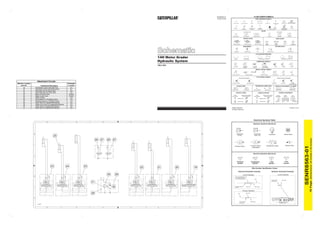
- 1. SENR8563-01 FLUID POWER SYMBOLS October 2006 BASIC COMPONENT SYMBOLS MAIN AUX. PUMP: VARIABLE and PUMP or MOTOR FLUID CONDITIONER SPRING CONTROL VALVES RESTRICTION LINE RESTRICTION 2-SECTION PUMP PRESSURE COMPENSATED (FIXED) VARIABILITY SPRING LINE RESTRICTION PRESSURE HYDRAULIC PNEUMATIC LINE RESTRICTION ATTACHMENT (ADJUSTABLE) (VARIABLE) COMPENSATION ENERGY TRIANGLES VARIABLE and PRESSURE COMPENSATED VALVES VALVE ENVELOPES VALVE PORTS ONE POSITION TWO POSITION THREE POSITION TWO-WAY THREE-WAY FOUR-WAY CONTROL VALVES CHECK VALVES AB AB P T P T BASIC SPRING SHUTTLE PILOT NORMAL POSITION SHIFTED POSITION INFINITE POSITION SYMBOL LOADED CONTROLLED MEASUREMENT ROTATING SHAFTS PRESSURE TEMPERATURE FLOW UNIDIRECTIONAL BIDIRECTIONAL FLUID STORAGE RESERVOIRS 14H Motor Grader Hydraulic System VENTED PRESSURIZED RETURN ABOVE FLUID LEVEL RETURN BELOW FLUID LEVEL COMBINATION CONTROLS 7WJ1-663 SOLENOID SOLENOID SOLENOID SOLENOID and SERVO THERMAL DETENT or MANUAL and PILOT PILOT or MANUAL MANUAL CONTROL SYMBOLS PUSH-PULL LEVER MANUAL SHUTOFF GENERAL MANUAL PUSH BUTTON PEDAL SPRING PILOT CONTROL SYMBOLS RELEASED PRESSURE REMOTE SUPPLY PRESSURE Attachment Circuits EXTERNAL RETURN INTERNAL Machine Location Schematic INTERNAL RETURN SIMPLIFIED COMPLETE SUPPLY PRESSURE Item No. Component Description Location ACCUMULATORS CROSSING AND JOINING LINES HYDRAULIC AND PNEUMATIC CYLINDERS 19 Plow/Dozeer Control Valve With Float B-1 20 Plow/Dozer Control Valve Without Float B-1 SPRING LOADED GAS CHARGED LINES CROSSING LINES JOINING SINGLE ACTING DOUBLE ACTING 21 Snow Wing Toe Tilt Control Valve B-2 22 Snow Wing Heel Lift Control Valve B-3 HYDRAULIC PUMPS HYDRAULIC MOTORS INTERNAL PASSAGEWAYS 23 Blade Lift Control Valve B-5,B-6 FIXED VARIABLE DISPLACEMENT FIXED VARIABLE DISPLACEMENT THREE TWO INFINITE 24 Ripper Control Valve B-5,B-6 DISPLACEMENT NON-COMPENSATED DISPLACEMENT NON-COMPENSATED POSITIONING POSITION POSITION 25 Ripper Cylinder D-6 UNIDIRECTIONAL UNIDIRECTIONAL 26 Accumulators For The Blade Cushion D-4 27 Mounting Valves For The Blade Cushion D-4 BIDIRECTIONAL BIDIRECTIONAL FLOW IN ONE DIRECTION PARALLEL FLOW CROSS FLOW FLOW ALLOWED IN EITHER DIRECTION 28 Check Valve For Supplemental Steering B-4 29 Electric Drive Pump For Supplemental Steeirng B-3 30 Check Valve For Supplemental Steering B-4 31 Relief Valve For Supplemental Steering B-4 © 2006 Caterpillar Printed in U.S.A. All Rights Reserved Electrical Symbols Table 6 5 4 3 2 1 Hydraulic Symbols (Electrical) G M D D Transducer Transducer Generator Electric Motor 25 (Fluid) (Gas / Air) (Dimensions: 24 inches x 34 inches) 26 27 26 27 Pressure Switch Temperature Switch Electrical Wire SENR8563-01 Pressure Switch (Adjustable) Electrical Symbols (Electrical) C C C1 C2 T Pressure Temperature Level Flow Symbol Symbol Symbol Symbol 23 24 23 22 21 20 19 Wire Number Identification Codes Electrical Schematic Example Hydraulic Schematic Example B 30 29 B Current Standard Current Standard Harness identification code S2 V1 This example indicates wire 135 in harness "AG". Wire Circuit Number Wire Color 16 Page, 31 325-AG135 PK-14 Identification 325-PK M Circuit Identification Number Wire Color Wire Gauge Previous Standard 28 1 T1 T2 Wire Wire Color A A 325-PK-14 B A Circuit Number Wire Gauge Identification (EXAMPLE VALVE) D14497 6 5 4 3 2 1
- 2. 15 18 13 14 6 5 4 3 2 1 8 12 25 26 10 F 9 11 F 6 22 8 8 12 8 23 9 13 14 17 18 5 17 27 28 11 29 30 2 7 19 E 10 E 3 4 1 20 21 16 16 22 C2 C1 16 16 D17025 15 24 5 D 6 7 D C C S2 (Dimensions: 24 inches x 34 inches) MAIN CONNECTOR LINE PILOT LINE SENR8563-01 DRAIN LINE S1 B B Hydraulic System For Implement And Steering Circuits Machine Location Schematic Item No. Component Description Location 4 1 Filter & Tank B-6 1 2 3 Piston Pump Combination valve A-4 A-3 4 Steering Accumulator B-3 5 Metering Pump For Steering D-3 6 Left Implement Valve Group D-6 7 Right Implement Valve Group D-3 8 Cylinder For Blade Lift F-2,F-6 9 Cylinder For Side Shift F-6 10 Swivel Group E-6 16 Page, Color 2, 11 Cylinder For Blade Tip F-5 12 Gerotor Motor For Circle Drive E-5 T1 T2 13 Left Steering Cylinder F-4 3 14 Right Steering Cyliinder F-4 15 Relief Valves For Steering Cylinders E-4 A V1 A 16 Left And Right Articulation Cylinders E-4 17 Centershift Cylinder F-3 2 18 Wheel Lean Cylinder F-3 D14496 6 5 4 3 2 1 THIS SCHEMATIC IS FOR THE 14H Components are shown installed on a fully operable machine with the key and engine off and transmission shifter in neutral. Refer to the appropriate Service Manual for Troubleshooting, Specifications and Systems Operations