
Empfohlen
Empfohlen
Weitere ähnliche Inhalte
Was ist angesagt?
Was ist angesagt? (20)
Ähnlich wie structured cabling.pdf
Ähnlich wie structured cabling.pdf (20)
Kürzlich hochgeladen
Kürzlich hochgeladen (20)
structured cabling.pdf
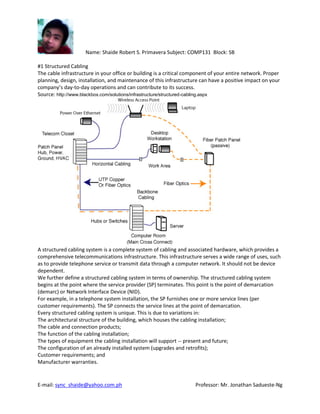
- 1. Name: Shaide Robert S. Primavera Subject: COMP131 Block: SB #1 Structured Cabling The cable infrastructure in your office or building is a critical component of your entire network. Proper planning, design, installation, and maintenance of this infrastructure can have a positive impact on your company’s day-to-day operations and can contribute to its success. Source: http://www.blackbox.com/solutions/infrastructure/structured-cabling.aspx A structured cabling system is a complete system of cabling and associated hardware, which provides a comprehensive telecommunications infrastructure. This infrastructure serves a wide range of uses, such as to provide telephone service or transmit data through a computer network. It should not be device dependent. We further define a structured cabling system in terms of ownership. The structured cabling system begins at the point where the service provider (SP) terminates. This point is the point of demarcation (demarc) or Network Interface Device (NID). For example, in a telephone system installation, the SP furnishes one or more service lines (per customer requirements). The SP connects the service lines at the point of demarcation. Every structured cabling system is unique. This is due to variations in: The architectural structure of the building, which houses the cabling installation; The cable and connection products; The function of the cabling installation; The types of equipment the cabling installation will support -- present and future; The configuration of an already installed system (upgrades and retrofits); Customer requirements; and Manufacturer warranties. E-mail: sync_shaide@yahoo.com.ph Professor: Mr. Jonathan Sadueste-Ng
- 2. The methods we use to complete and maintain cabling installations are relatively standard. The standardization of these installations is necessary because of the need to ensure acceptable system performance from increasingly complex arrangements. The U.S. cabling industry accepts the American National Standards Institute (ANSI), in conjunction with TIA/EIA, as the responsible organization for providing and maintaining standards and practices within the profession. It has published a series of standards to design, install, and maintain cabling installations. These help to ensure a proper cabling installation. The benefits of these standards include: Consistency of design and installation; Conformance to physical and transmission line requirements; A basis for examining a proposed system expansion and other changes; and Uniform documentation. The industry standard term for a network installation that serves a relatively small area (such as a structured cabling installation serving a building) is a local area network (LAN). There are also metropolitan area networks (MANs) and wide area networks (WANs). Structured cabling installations typically include: entrance facilities; vertical and horizontal backbone pathways; vertical and horizontal backbone cables; horizontal pathways; horizontal cables; work area outlets; equipment rooms; telecommunications closets; cross-connect facilities; multi-user telecommunications outlet assemblies (MUTOA); transition points; and consolidation points. The entrance facility includes the cabling components needed to provide a means to connect the outside service facilities to the premises cabling. This can include service entrance pathways, cables, connecting hardware, circuit protection devices, and transition hardware. An entrance facility houses the transition outside plant cabling to cabling approved for intrabuilding construction. This usually involves transition to fire-rated cable. The entrance facility is also the network demarc between the SP and customer premises cabling (if required). National and regional electrical codes govern placement of electrical protection devices at this point. The location of the entrance facility depends on the type of facility, route of the outside plant cabling (e.g. buried or aerial), building architecture, and aesthetic considerations. The four principal types of entrance facilities include underground, tunnel, buried, and aerial. (We will cover only aerial entrances in this article.) In an aerial entrance, the SP cables provide service to a building via an overhead route. Aerial entrances usually provide the lowest installation cost, and they're readily accessible for maintenance. However, they're subject to traffic and pedestrian clearances, can damage a building's exterior, are susceptible to environmental conditions (such wind and ice), and are usually joint-use installations with the power company, CATV company, and telephone or data service providers. Backbone cabling. From the entrance facility, the structured cabling network branches out to other buildings, as well as from floor to floor within a building on the backbone cabling system. We use the term backbone to describe the cables handling the major network traffic. The ANSI/TIA/EIA-568-A standard defines backbone cabling as follows: "The function of the backbone cabling is to provide interconnections between telecommunications closets, equipment rooms, and entrance facilities in the telecommunications cabling system structure. Backbone cabling consists of the backbone cables, intermediate and main cross-connects, mechanical terminations, and patch cords or jumpers used for backbone-to-backbone cross-connection. Backbone cabling also includes cabling between buildings." Interbuilding and intrabuilding are two types of backbone cables. Interbuilding backbone cable handles traffic between buildings. Intrabuilding backbone cable handles traffic between closets in a single building.
- 3. This standard identifies two levels of backbone cabling. First-level backbone is a cable between a main cross-connect (MC) and intermediate cross-connect (IC) or horizontal cross-connect (HC). Second-level backbone exists between an IC and HC. The main components of backbone cabling are: Cable pathways: shafts, conduits, raceways, and floor penetrations (such as sleeves or slots) that provide routing space for the cables. The actual cables: optical fiber, twisted-pair copper, coaxial copper, or some combination of these. (Note: You should avoid areas where potential sources of EMI or electromagnetic interference may exist when planning the routing and support structure for copper cabling.) Connecting hardware: connecting blocks, patch panels, interconnections, cross-connections, or some combination of these components, and Miscellaneous support facilities: cable support hardware, firestopping and grounding hardware. Note: The terms horizontal and backbone (previously called riser) evolved from the orientations typical for functional cables of these types. However, the physical orientation of the cabling has no bearing on classifying the cable as horizontal or backbone. The useful life of a backbone cabling system consists of several planned growth periods (typically three to 10 years). This is shorter than the life expectancy of the premises cabling system. Cabling connectors. A connector is a mechanical device you use to interface a cable to a piece of equipment or one cable to another. The role of the connector is to provide a coupling mechanism that keeps loss to a minimum. In the case of fiber, it allows light impulses to transfer from one connector to another. For copper, it allows electrical signals to transfer from one connector to another. A good connection requires aligning the connectors, preventing the connectors from unintentional separation, and efficient transferring of light or electricity from one connector to the other. A connector demonstrates durability by withstanding hundreds of insertion and withdrawal cycles without failing. We calculate this as mean time between failures (MTBF). Connectors are as essential to the integrity of the entire telecommunications network as is the cable itself. Connectors align, attach, and decouple the media to a transmitter, receiver, another media of same or similar type, an active telecommunications device, or a specified passive telecommunications device. Source: http://ecmweb.com/basics/basics-structured-cabling #2 Network Planning – is an iterative process, encompassing topological design, network-synthesis, and network-realization, and is aimed at ensuring that a new telecommunications network or service meets the needs of the subscriber and operator. The process can be tailored according to each new network or service. Source: http://www.tandemlogistics.com/resources/glossary-of-terms.php
- 4. #3 Structured cabling plan Is the plan of building or campus telecommunications cabling infrastructure that consists of a number of standardized smaller elements (hence structured) called subsystems. #4 Difference of structured cabling plan and a network plan Structured cabling plan is the The cable infrastructure in your office or building is a critical component of your entire network while network plan is the process can be tailored according to each new network or service. #5 What is RJ45, RJ11, CAT5E, CAT5, CAT6, CAT6A? RJ45 - is a standard type of connector for network cables. RJ45 connectors are most commonly seen with Ethernet cables and networks. Source: http://compnetworking.about.com/od/networkcables/g/bldef_rj45.htm RJ11 - More commonly known as a phone connector, phone jack or phone line, the RJ-11 is short for Registered Jack-11 and is a four or six wire connection primarily used for telephones and computer
- 5. modem connectors in the United States. In the picture to the right, is an example image of what the RJ11 phone connection looks like. Although this cable can be used to connect your modem to the Internet it should not be confused with the RJ-45 connector, which is used with your network card. Source: http://www.computerhope.com/jargon/r/rj11.htm CAT5E - Short for Category 5 Enhanced, Cat-5e network cabling is used as a cabling infrastructure for 10BASE-T (Ethernet), full duplex 100BASE-TX (Fast Ethernet) and 1000BASE-T (Gigabit Ethernet, or GbE) networks. The Cat 5e standard provides performance of up to 100 MHz and can be used up to a maximum length of 100 meters. As with Category 5 (Cat-5) cables, Cat 5e cables typically consist of fourunshielded twisted pairs (UTP) of copper wire terminated by RJ45connectors. Cat 5e is distinguished from the original Cat 5 standard primarily in its performance requirements. Cat 5e has stricter specifications in a number of areas, including Near-End Crosstalk (NEXT), Power Sum Equal-Level Far-End Crosstalk (PS-ELFEXT), attenuation and return loss. The Cat 5e standard was first released in 1999 as part of the Telecommunications Industry Association’s TIA/EIA-568-5-A document specification. The Cat 5e cable standard is backward compatible with the Cat 3 and Cat 5 cable standards. Source: http://www.webopedia.com/TERM/C/Cat_5e.html CAT5 - Short for Category 5, network cabling that consists of four twisted pairs of copper wire terminated by RJ45 connectors. Cat-5 cabling supports frequencies up to 100 MHz and speeds up to 1000 Mbps. It can be used forATM, token ring, 1000Base-T, 100Base-T, and 10Base-T networking.
- 6. Computers hooked up to LAN s are connected using Cat-5 cables, so if you're on a LAN, most likely the cable running out of the back of your PC is Category 5. Cat-5 is based on the EIA/TIA 568 Commercial Building Telecommunications Wiring Standard developed by the Electronics Industries Association as requested by the Computer Communications Industry Association in 1985. Source: http://www.webopedia.com/TERM/C/Cat_5.html CAT6 - is an Ethernet cable standard defined by the Electronic Industries Association and Telecommunications Industry Association (commonly known as EIA/TIA). CAT6 is the sixth generation of twisted pair Ethernet cabling. CAT6 cable contains four pairs of copper wire like the previous generation CAT5. Unlike CAT5, however, CAT6 fully utilizes all four pairs. CAT6 supports Gigabit Ethernet speeds up to 1 gigabit per second (Gbps) and supports communications at more than twice the speed ofCAT5e, the other popular standard for Gigabit Ethernet cabling. An enhanced version of CAT6 called CAT6a supports up to 10 Gbps speeds. As with all other types of twisted pair EIA/TIA cabling, individual CAT6 cable runs are limited to a maximum recommended length of 100m (328 feet). Printing along the length of the cable sheath identifies it as CAT6. Source: http://compnetworking.about.com/od/ethernet/g/cat6-cables.htm
- 7. CAT6A - The latest standard from the TIA for enhanced performance standards for twisted pair cable systems was defined in February 2008 in ANSI/TIA/EIA-568-B.2-10. Category 6a (or Augmented Category 6) is defined at frequencies up to 500 MHz—twice that of Cat. 6. Category 6a performs at improved specifications, in particular in the area of alien crosstalk as compared to Cat 6 UTP (unshielded twisted pair), which exhibited high alien noise in high frequencies. The global cabling standard ISO/IEC 11801 has been extended by the addition of amendment 2. This amendment defines new specifications for Cat. 6A components and Class EA permanent links. These new global Cat. 6A/Class EA specifications require a new generation of connecting hardware offering far superior performance compared to the existing products that are based on the American TIA standard. The most important point is a performance difference between ISO/IEC and EIA/TIA component specifications for the NEXT transmission parameter. At a frequency of 500 MHz, an ISO/IEC Cat. 6A connector performs 3 dB better than a Cat. 6A connector that conforms with the EIA/TIA specification. 3 dB equals 50% reduction of near-end crosstalk noise signal power; see 3dB-point. Confusion therefore arises because of the different naming conventions and performance benchmarks laid down by the International ISO/IEC and American TIA/EIA standards, which in turn are different from the regional European standard, EN 50173-1. In broad terms, the ISO standard for Cat6A is the highest, followed by the European standard and then the American (1 on 1 matching capability). Source: http://en.wikipedia.org/wiki/CAT6
- 8. #6 What is Ethernet? Ethernet is a physical and data link layer technology forlocal area networks (LANs). Ethernet was invented by engineer Robert Metcalfe. When first widely deployed in the 1980s, Ethernet supported a maximum theoretical data rate of 10 megabits per second (Mbps). Later, so-called "Fast Ethernet" standards increased this maximum data rate to 100 Mbps. Today, Gigabit Ethernet technology further extends peak performance up to 1000 Mbps. Higher level network protocols like Internet Protocol (IP) use Ethernet as their transmission medium. Data travels over Ethernet inside protocol units called frames. The run length of individual Ethernet cables is limited to roughly 100 meters, but Ethernet networks can be easily extended to link entire schools or office buildings using network bridge devices. Source: http://compnetworking.about.com/cs/ethernet1/g/bldef_ethernet.htm #7 What is Giga Ethernet? Gigabit Ethernet is part of the family of Ethernet computer networking and communication standards. The Gigabit Ethernet standard supports a theoretical maximum data rate of 1 gigabit per second (Gbps) (1000 Mbps). When first developed, some thought achieving gigabit speeds with Ethernet would require using fiber optic or other special cables. However, today's Gigabit Ethernet works using twisted pair copper cable (specifically, the CAT5e and CAT6 cabling standards) similar to older 100 Mbps Fast Ethernet (that works over CAT5 cables). Newer home broadband routers now support Gigabit Ethernet along with other mainstream computer network equipment. Gigabit Ethernet also provides backward compatibility to older 100 Mbps and 10 Mbps legacy Ethernet devices: Connections to these devices function normally but perform at the lower speed. Also Known As: 1000 Mbps Ethernet Source: http://compnetworking.about.com/cs/gigabitethernet/g/bldef_gigaenet.htm #8 What is the difference between a Ethernet and giga Ethernet?
- 9. Gigabit is 1000mbps (megabits per second) Ethernet, which is 10x faster than 100mbps Ethernet, which is 10x faster than 10mbps Ethernet. By: eibgrad Source: http://www.tomshardware.com/forum/29154-42-ethernet-gigabit-ethernet#. #9 What is hub, switch, router, switch hub? Hub – An Ethernet hub, active hub, network hub, repeater hub, multiport repeater or hub is a device for connecting multiple Ethernet devices together and making them act as a single network segment. It has multiple input/output(I/O) ports, in which a signal introduced at the input of any port appears at the output of every port except the original incoming. A hub works at the physical layer (layer 1) of the OSI model.[1] The device is a form of multiport repeater. Repeater hubs also participate in collision detection, forwarding a jam signal to all ports if it detects a collision. Some hubs may also come with a BNC and/or Attachment Unit Interface (AUI) connector to allow connection to legacy 10BASE2 or 10BASE5 network segments. The availability of low-priced network switches has largely rendered hubs obsolete but they are still seen in 20th century installations and more specialized applications. Source: http://en.wikipedia.org/wiki/Ethernet_hub Switch – A switch is a network hardware device that allows communication between devices within a network, like your local home network. Most home and small business routers contain built-in switches. The Switch is Also Known As: A switch is more correctly called a network switch though you'll rarely see one referred to as such. A switch is also uncommonly called a switching hub. Important Switch Facts: Switches are found in both unmanaged and managed forms. Unmanaged switches have no options and simply work out of box. Managed switches have advanced options that can be configured. Managed switches also contain software called firmware that should be updated as released by the switch manufacturer. Switches connect to other network devices via network cables only and thus do not require driversto operate in Windows or other operating systems. Source: http://pcsupport.about.com/od/componentprofiles/p/switch.htm
- 10. Router – Routers are small physical devices that join multiple networks together. Technically, a router is a Layer 3 gateway device, meaning that it connects two or more networks and that the router operates at the network layer of the OSI model. Home networks typically use a wireless or wired Internet Protocol (IP) router, IP being the most common OSI network layer protocol. An IP router such as a DSL or cable modembroadband router joins the home's local area network (LAN) to the wide-area network (WAN)of the Internet. Source: http://compnetworking.about.com/cs/routers/g/bldef_router.htm Switch hub – Short for port-switching hub, a special type of hub that forwards packets to the appropriate port based on the packet's address. Conventional hubs simply rebroadcast every packet to every port. Since switching hubs forward each packet only to the required port, they provide much better performance. Most switching hubs also support load balancing, so that ports are dynamically reassigned to different LAN segments based on traffic patterns.
- 11. Some newer switching hubs support both traditional Ethernet (10 Mbps) andFast Ethernet (100 Mbps) ports. This enables the administrator to establish a dedicated, Fast Ethernet channel for high-traffic devices such as servers. Source: http://www.webopedia.com/TERM/S/switching_hub.html #10 What is the difference between switch and hub? A network router is a more sophisticated network device compared to either a network switchor a network hub. Like hubs and switches, routers are typically small, box-like pieces of equipment that multiple computers can connect to. Each features a number of ports on the front or back of the unit that provide the connection points for these computers, a connection for electric power, and a number of LED lights to display device status. While routers, hubs and switches all share similar physical appearance, routers differ substantially in their inner workings. Traditional routers are designed to join together multiple local area networks (LANs) with a wide area network (WAN). Routers serve as intermediate destinations for network traffic. They receive incoming network packets, look inside each packet to identify the source and target network addresses, then forward these packets where needed to ensure the data reaches its final destination. Routers for home networks (often called broadband routers) are designed specifically to join the home (LAN) to the Internet (WAN) for the purpose of Internet connection sharing. In contrast, switches (and hubs) are not capable of joining multiple networks or sharing an Internet connection. A network with only switches (hubs) must instead designate one computer as the gateway to the Internet, and that device must possess two network adapters for sharing, one for the home LAN and one for the Internet WAN. With a router, all home computers connect to the router as peers, and the router performs all gateway functions. Additionally, broadband routers contain several features beyond those of traditional routers such as integrated DHCP server and network firewall support. Most notably, though, broadband routers typically incorporate a built-in Ethernet switch. This allows several switches (hubs) to be connected to them, as a means to expand the local network to accommodate more Ethernet devices. Wi-Fi wireless networks also utilize routers but technically do not have the concept of a wireless switch or hub, although a wireless access point can be roughly compared to a wired switch. Source: http://compnetworking.about.com/od/homenetworkhardware/f/routervsswitch.htm