Jawaban uts astl ganjil analisa sistem tenaga
•
0 gefällt mir•858 views

This document contains the answers to questions on a mid-semester exam for a power systems analysis course. The questions cover topics like: - Deriving the power mismatch equation and Jacobian matrix for the Newton Raphson load flow method. - Discussing the steady-state modeling of power system components. - Converting component parameters in a sample power system diagram from real to per unit values. - Constructing the admittance matrix and obtaining the Thevenin equivalent circuit for a part of the sample system. - Calculating line power flows and system losses based on a given load and generator power factors.

Empfohlen
Weitere ähnliche Inhalte
Was ist angesagt?
Was ist angesagt? (20)
Ähnlich wie Jawaban uts astl ganjil analisa sistem tenaga
Ähnlich wie Jawaban uts astl ganjil analisa sistem tenaga (20)
Mehr von suparman unkhair
Mehr von suparman unkhair (20)
Kürzlich hochgeladen
Kürzlich hochgeladen (20)
Jawaban uts astl ganjil analisa sistem tenaga
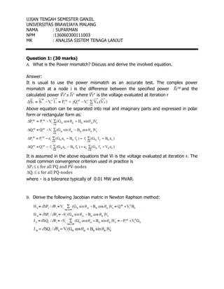
- 1. UJIAN TENGAH SEMESTER GANJIL UNIVERSITAS BRAWIJAYA MALANG NAMA : SUPARMAN NPM :136060300111003 MK : ANALISA SISTEM TENAGA LANJUT Question 1: (30 marks) A. What is the Power mismatch? Discuss and derive the involved equation. Answer: It is usual to use the power mismatch as an accurate test. The complex power mismatch at a node i is the difference between the specified power ̅ and the calculated power ̅ ̅ where ̅ is the voltage evaluated at iteration r Above equation can be separated into real and imaginary parts and expressed in polar form or rectangular form as: It is assumed in the above equations that Vi is the voltage evaluated at iteration r. The most common convergence criterion used in practice is B. Derive the following Jacobian matric in Newton Raphson method:
- 2. Answer: Equation 1 ∑ ( ) Verification: ∑ ( ) ( ) ( ) Equation 2 ( ) Verification: ∑ ( ) ( ) ( ) ( ) Equation 3 ∑ ( ) Verification: ∑ ( )
- 3. ( ) ( ) ( ) Equation 4 ( ) Verification: ∑ ( ) ( ) ( ) Question 2: (20 marks) Discuss briefly the steady state (load flow) modeling of each power system component involved in the power system. Answer: steady state (steady / steady) is the normal condition of post-occurring disorders in an RL circuit with t ≠ 0 and steady state always has the same magnitude but opposite in sign to declare the value zero from existing flows. Picture below is an image of power system modeling and graphic images of steady state conditions:
- 4. Picture below is an image of power system modeling Picture below is graphic images of steady state conditions:
- 5. Question 3: (50 marks) Figure 1 shows three phase system that are connected to generators A, B, C and D at 11kV level. The five nodes of the system with the specific ID are given in the figure. The power supplies the load through node 2 at 132kV level. The reactance of the transmission line and component parameters in per unit are shown in the Figure. a) Change all components in Figure 1 which are given in real parameters to per unit system. Note: use 100MVA as reference to determine the per unit system. Answer: VBase4 =33 KV VBase5 =33x(11/33)=11 KV VBase3 =11x(11/11)=11 KV VBase2 =33x(11/33)=11 KV VBase1 =11x(11/11)=11 KV ZBase gen 1 = (11 KV) 2 /(100 MVA)=1,21 Ω ZBase 2 = (11 KV) 2 /(100 MVA)=1,21 Ω ZBase 5 = (11 KV) 2 /(100 MVA)=1,21 Ω ZBase 4 = (33 KV) 2 /(100 MVA)=10,89 Ω ZBase 1 = (11 KV) 2 /(100 MVA)=1,21 Ω
- 6. ZGen / Z5 = 1,21 x (11 ) 2 /(33) x (200/100)=0,26 pu Z1 = 1,21 x (11 ) 2 /(132) x (200/100)=0,16 pu Z2 = 1,21 x (11 ) 2 /(11) x (100/100)=1,21 pu Z3 = 1,21 x (11 ) 2 /(132) x (150/100)=0,012 pu Z4= 10.89 x (33 ) 2 /(33) x (100/100)=10,89 pu Z5 = 0 b) Construct the admittance matrix of the system. Answer: Y11 Y12 Y13 Y14 Y15 V1 I1 Y21 Y22 Y23 Y24 Y25 V2 I2 Y31 Y32 Y33 Y34 Y35 V3 = I3 Y41 Y42 Y43 Y44 Y45 V4 I4 Y51 Y52 Y53 Y54 Y55 V5 I5 c) Obtain the Thevenin equivalence circuit at bus 2. Answer:
- 7. V 1 V 2 V 3 V 4 V 5 I 1 I 2 I 3 I 4 I 5 Y 10 Y 40 Y 12 Y 24 Y 23 Y 20 Y 30 Y 45 a Y 45 b Y 45 c Y 50 d) Assume that the power load required in the system is about 525 MW and all gernerators running on pf 0.9, determine the power flow in the Lines: 1-2, 2-3, 2-4 and calculate the system losses. Answer: