1. Keep it watertight with
Patent Pending
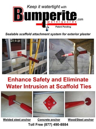
Sealable scaffold attachment system for exterior plaster
Enhance Safety and Eliminate
Water Intrusion at Scaffold Ties
Welded steel anchor Concrete anchor Wood/Steel anchor
Toll Free (877) 490-8884
2. Patent Pending
THE PROBLEM
Water intrusion at conventional push pull wire ties.
THE SOLUTION
Sealable scaffold attachments.
Bumperite Waterguards enhance Safety and eliminate Liability
due to leaks caused by conventional scaffold wire ties assemblies.
3. Patent Pending
• SAFETY
OSHA compliant
Engineered and tested
structural attachment for
scaffolding (4500) lbs.
Report # L-06-3265
Ideal for tarped or enclosed
scaffolds in high wind
conditions.
• REDUCED LABOR COST
Eliminate costly end laps
and their cuts to building
papers verses conventional
scaffold wire ties.
Removable bumper allows
easy access to difficult
work areas.*
Promotes the continuous
installation of building
materials.
• RELIABILITY
Water tested to ASTM
E331-00 at Smith-Emery
laboratories, Inc. Los
Angeles, CA. Report
# L-06-3059
*See installation instructions.
WARRANTY: Bumperite Waterguards, LLC. liability expressed or implied is limited to the selling price of any defected goods. User shall determine the suitability
of this product for the intended use by doing field test before using, and assumes all risk and liabilities in connection and seals therewith.
4. Patent Pending
Welded Steel Anchor
INSTALLATION PROCEDURE
• Determine spacing
requirement to insure safe
scaffold erection.*
• Measure distance between
slab edge bent plate and
outer face of stud framing. 1/8”
• Cut the anchor strut to
length as to flush out with
face of stud framing.
• Align the anchor strut with
the bent plate and stud
framing (true, square, and
plumb) per detail.
• Weld anchor strut to
building bent plate per
welding detail shown.
• The use of a certified welder
and E7018 rod or equal is
recommended.
*Spacing requirements for application should be determined by a competent scaffold erector or structural engineer per building and safety codes prior to
installation. The temporary disconnection and reconnection of this product at erected scaffold should only be performed one connection at a time and
only after it is determined safe to do so. The final determination of safety is the sole responsibility of the end user and should be determined by a
competent and qualified person. Follow all OSHA, Federal, State, and Local requirements to ensure scaffold safety.
To ensure safety, use only components manufactured by Bumperite Waterguards, LLC. at scaffold attachment.
5. Bumperite Attachment To Steel Bent Plate
Illustrations and load Capacity provided by FICCADENTI & WAGGONER, Consulting Structural Engineers, Inc
6. Patent Pending
WOOD INSTALLATION PROCEDURE
• Determine spacing
requirement to insure safe
scaffold erection.*
• Review screw matrix
provided to determine screw
size and quantity required
for safe installation.
• Install Bumperite anchor
plate where suitable framing
and or backing occurs to
ensure sufficient strength
required to carry intended
scaffold load.
• Apply compatible sealant
between Bumperite anchor
plate & building papers to
ensure seal at screws.
• Ensure complete screw
embedment at pre-drilled
holes in anchor plate.
See engineered detail.
*Spacing requirements for application should be determined by a competent scaffold erector or structural engineer per building and safety codes prior to
installation. The temporary disconnection and reconnection of this product at erected scaffold should only be performed one connection at a time and
only after it is determined safe to do so. The final determination of safety is the sole responsibility of the end user and should be determined by a
competent and qualified person. Follow all OSHA, Federal, State, and Local requirements to ensure scaffold safety.
To ensure safety, use only components manufactured by Bumperite Waterguards, LLC. at scaffold attachment.
7. Bumperite Attachment to Wood Framing
Allowable Nail Withdraw Value (P):
Fastener Type w/ 2 Fasteners w/ 4 Fasteners w/ 6 Fasteners w/ 8 Fasteners
16d Nail 40 lbs. 80 lbs. 120 lbs. 160 lbs.
10d Nail 36 lbs. 72 lbs. 108 lbs. 144 lbs.
Allowable Screw withdraw Value (P):
Fastener Type
(Screw Size x
Length) w/ 2 Fasteners w/ 4 Fasteners w/ 6 Fasteners w/ 8 Fasteners
#12 x 2" Screw 410 lbs. 820 lbs. 1080 lbs. 1232 lbs.
#12 x 11⁄2" Screw 308 lbs. 616 lbs. 924 lbs. 1232 lbs.
#10 x 2" Screw 360 lbs. 720 lbs. 1080 lbs. 1232 lbs.
#10 x 11⁄2" Screw 270 lbs. 540 lbs. 810 lbs. 810 lbs.
Illustrations and load Capacity provided by FICCADENTI & WAGGONER, Consulting Structural Engineers, Inc
8. Patent Pending
STEEL FRAMED INSTALLATION PROCEDURE
• Determine spacing
requirement to insure safe
scaffold erection.*
• Review backing plate
requirements.
• Install Bumperite anchor
plate over 12 gage backing
plate per diagram to ensure
sufficient strength required
to carry intended scaffold
load.
• Apply compatible sealant
between Bumperite anchor
plate & building papers to
ensure seal at screws.
• Ensure complete screw
embedment at pre-drilled
holes in anchor plate.
See engineered detail.
*Spacing requirements for application should be determined by a competent scaffold erector or structural engineer per building and safety codes prior to
installation. The temporary disconnection and reconnection of this product at erected scaffold should only be performed one connection at a time and
only after it is determined safe to do so. The final determination of safety is the sole responsibility of the end user and should be determined by a
competent and qualified person. Follow all OSHA, Federal, State, and Local requirements to ensure scaffold safety.
To ensure safety, use only components manufactured by Bumperite Waterguards, LLC. at scaffold attachment.
9. Bumperite Attachment to Light Gauge Framing
ALLOWABLE FORCE (P) = 1,000 LBS.
Minimum Design Requirements :
:
• For scaffold application this product complies w/ OSHA requirements
• 12 ga. Deck Edge Clip
• 18 ga. Wall Studs
• 8”x12 ga.x11/2” Fl. Track
• Track Blocking must be located within 6” of the Deck Edge Clip
Illustrations and load Capacity provided by FICCADENTI & WAGGONER, Consulting Structural Engineers, Inc
10. Bumperite Attachment to Light Gauge Framing
ALT. #1
6” x 16GA x 1-1/2” FLANGE
TRACK W / CUPPED
FLANGES @ ENDS EXTEND
WEB TAB ATTACHMENT TO
(E) STUD AS SHOWN
(4) # 8 S.M.S. EA. END
ALLOWABLE FORCE (P) = 500 LBS.
Minimum Design Requirements :
:
• For scaffold application this product complies w/ OSHA requirements
• 12 ga. Deck Edge Clip
• 18 ga. Wall Studs
• 6”x16 ga.x1-1/2” Fl. Track
• Track Blocking must be located within 6” of the Deck Edge Clip
Illustrations and load Capacity provided by FICCADENTI & WAGGONER, Consulting Structural Engineers, Inc
11. Patent Pending
CONCRETE INSTALLATION PROCEDURE
• Determine Bumperite
spacing requirement
and concrete psi
values suitable for
safe scaffold
erection.*
• Install Bumperite
anchor plate at
concrete slab edge
with a minimum of
two concrete
anchors bolts, see
engineered detail.
• Install concrete
anchors per
manufactures
installation
guidelines.
• Ensure complete
anchor bolt
embedment for
maximum strength.
See engineered detail.
*Spacing requirements for application should be determined by a competent scaffold erector or structural engineer per building and safety codes prior to
installation. The temporary disconnection and reconnection of this product at erected scaffold should only be performed one connection at a time and
only after it is determined safe to do so. The final determination of safety is the sole responsibility of the end user and should be determined by a
competent and qualified person. Follow all OSHA, Federal, State, and Local requirements to ensure scaffold safety.
To ensure safety, use only components manufactured by Bumperite Waterguards, LLC. at scaffold attachment.
12. Bumperite Attachment to Concrete Deck
Illustrations and load Capacity provided by FICCADENTI & WAGGONER, Consulting Structural Engineers, Inc
13. Patent Pending
BUMPERITE QUICK-TAB
Optional feature
• The specially designed
Quick-tab is a scaffold
erectors dream.
• Fast and easy installation
with no hassle.
• A temporary attachment
to building slab edge
during scaffold erection
prior to exterior wall
framing and final welded
attachment of Bumperite
Waterguard.
• Available upon
request.
• See engineered detail
• WARNING: The Quick-
tab attachment is not to
be used at tarped or
enclosed scaffolds.
*Spacing requirements for application should be determined by a competent scaffold erector or structural engineer per building and safety codes prior to
installation. The temporary disconnection and reconnection of this product at erected scaffold should only be performed one connection at a time and
only after it is determined safe to do so. The final determination of safety is the sole responsibility of the end user and should be determined by a
competent and qualified person. Follow all OSHA, Federal, State, and Local requirements to ensure scaffold safety.
To ensure safety, use only components manufactured by Bumperite Waterguards, LLC. at scaffold attachment.
15. Patent Pending
RECOMMENDED METHOD OF SEAL AT CONNECTION
Manufacturer recommends the use of Densglass Gold exterior sheathing, butyl
sealant, Tyvek Straight Flash, minimum UU-B-790a grade D, building paper, and
three coat cement plaster per testing report L-06-3059 from Smith-Emery
Laboratories, Inc. using test method ASTM E331-00
WARRANTY: Bumperite Waterguards, LLC. liability expressed or implied is limited to the selling price of any defected goods. User shall determine
the suitability of this product for the intended use by doing field test before using, and assumes all risk and liabilities in connection therewith.
17. Patent Pending
RECOMMENDED METHOD OF SEAL AT WOOD / STEEL FRAMED
ANCHOR PLATE TO EXTERIOR WATER MANAGEMENT SYSTEM
Water tested to ASTM E 1105-00 & ASTM E 331-00 by Architectural Testing, Inc.
Report No: 90353.01-701-43
WARRANTY: Bumperite Waterguards, LLC. liability expressed or implied is limited to the selling price of any defected goods. User shall determine
the suitability of this product for the intended use by doing field test before using, and assumes all risk and liabilities in connection therewith.
18. Step by Step at wood / steel framed plates Patent Pending
19. Patent Pending
BUMPERITE - VS - WIRE TIES
OSHA 1926.451(c)(1) states,
Capacity- - Scaffolds and scaffold components must support
at least 4 times the maximum intended load.
Sealable & strength Difficult to seal & weaker
Testing at Smith-Emery Laboratories suggest that the Bumperite Waterguard peak
tension load is MANY TIMES STRONGER than conventional double strand #12
black annealed wire tie assemblies.
See Our Web Site At
Bumperite.com
For More Information Please Contact Us At
INFO@BUMPERITE.COM
Toll free (877) 490-8884
Bumperite Waterguards, LLC.