
Empfohlen
Weitere ähnliche Inhalte
Ähnlich wie Ortho projection.ppt
Ähnlich wie Ortho projection.ppt (20)
Kürzlich hochgeladen
Kürzlich hochgeladen (20)
Ortho projection.ppt
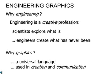
- 1. ENGINEERING GRAPHICS Engineering is a creative profession: … engineers create what has never been’ Why graphics ? Why engineering ? … a universal language … used in creation and communication ‘scientists explore what is …
- 2. But graphic images from 15,000-18,000 BC communicate very effectively today Red ochre cave painting Vallon-Pont-d'Arc, France
- 3. A universal graphic language? Egyptian hieroglyphs were based on recognisable graphic symbols
- 4. Chinese characters became much more abstract
- 5. Many Western languages use standard symbols, but not in a universal way … Hello Bon Jour Guten Tag G’day ...
- 6. Sketches Leonardo da Vinci (1452-1519) Perspective projection Parallel projection We will study ‘orthographic’ projection systems in detail
- 7. a printer Imagine trying to describe this printer, precisely, using verbal communication
- 8. Orthographic projection • Multi-view drawings provide the most accurate description of 3D objects and structures for engineering, manufacturing, and construction requirements
- 10. Orthographic Projection • The word Orthographic means 'to draw at right angles'. Hence orthographic projection is a means of visualising an object by projecting its edges at right angles onto the projection plane. • In practice, orthographic projection uses two main planes, called the principal planes of projection or planes of reference
- 11. Orthographic Projection Projectors are orthogonal (90°) to projection surface
- 12. Orthographic Projection In engineering, there are two systems of projection: – First Angle Projection – Europe, Asia and former European colonies in Africa and parts of Australia – Third Angle Projection – Used in the USA and Canada, in Africa where American development is taking place and parts of Australia
- 13. First Angle Projection • Fist Angle Projection - object positioned in space in the First Quadrant. • View on the vertical plane - ELEVATION • View on the horizontal plane - PLAN • To obtain the views as they would appear on a sheet of paper, the horizontal plane is opened out about the intersection of the planes. The line of intersection is called the XY line, ground line or folding line.
- 19. Glass projection box End elevation Plan Elevation
- 20. YY line or fold line Vertical plane End vertical plane Horizontal plane XY lines or fold lines
- 21. Vertical plane End vertical plane Horizontal plane YY line of fold line XY lines or fold lines Elevation End elevation Plan
- 27. Front Elevation End Elevation (Left) End Elevation (Right) Plan View
- 28. First Angle Plan View Front Elevation End Elevation (Left) End Elevation (Right)
- 29. Advantages and Disadvantages • Preserves both distances and angles – Shapes preserved – Can be used for measurements • Building plans • Manuals • Cannot see what object really looks like because many surfaces hidden from view – Often we add the isometric (3D)