VVIP Pune Call Girls Parvati Gaon WhatSapp Number 8005736733 With Elite Staff...
Us873655
1. No. 873,655.
A. W. BERKNER,
ELEVATOR BUCKET,
APPLICATION FILED MAR,26,1907.
3-vevitov
<1%2/? A Zerza."Ritvacosco
06eges/27%zee/7 2662s6azzam u-6. elitotic
2. O
5
20
25
30
35
40
45
50
55
UNITED STATES PATENT OFFICE.
ADOLPH. W. BERKNER, OF CAYUGA, NORTH DAKOTA.
ELEVATOR-BUCKET.
No. 873,655. Specification of Letters Patent. Patented Dec. 10, 1907.
Application filedMarch 26, 1907, SerialNo, 364,667,
To all whom it may concern:
Beit known that I, ADOLPH. W. BERKNER,
a citizen of the United States, residing at
Cayuga, in the county of Sargent and State
of North Dakota, have invented new and
useful Improvements in Elevator-Buckets,
of which the following is a specification.
This invention relates to buckets intended
for use in grain elevators, and it relates more
particularlyto a bucket construction, where
bytheoverloadingof thebucket isprevented.
The invention has for one of its objects to
improve and simplify the construction of de
vices of this character so as to be compara
tively easy and inexpensive to manufacture,
of substantial and durable design, and reliable and efficient in use.
A further object of the invention is the
provision of an elevator bucket that is
equippedwith a yieldinglysupported bottom
that is adapted to open under the weight of
an excessive amount of material and auto
matically closed when theweightor quantity
reaches a certain predetermined amount so
that the buckets of the elevator will each de
liver accurate amounts.
With these objects in view and others, as
will appear as the description proceeds, the
invention comprises the various novel fea
tures of construction and arrangement of
parts as will be more fully described herein
after and set forth with particularity in the
claims appended hereto.
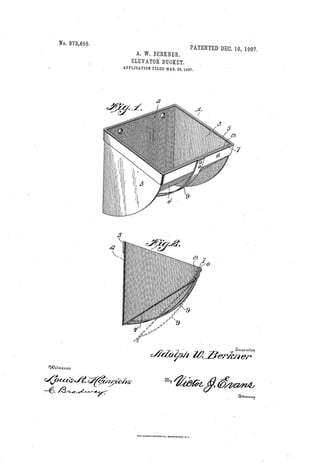
In the accompanying drawing, which illus
trates one of the embodiments of the inven
tion, Figure 1 is a perspective of the bucket.
Fig. 2is a transversesectionshowingthebot
tom closed and opened by full and dottedlines respectively.
Similar reference characters are employed
to designate similar parts throughout the
several views.
Referring to the drawings, 1 designates the
body of the bucket that is preferably made
of sheet metal and bent to form a vertical
back wall 2 and sector shaped end walls 3
disposed laterally with respectto theback
wall, the top edges of the end walls 3 being
disposed at an oblique or acute angle with
respect to the vertical, as shown in Fig. 2.
Disposed between the ends 3 is a bottom
plate 4 arranged downwardly inclined to
ward the bottom edge ofthebackwall2, and
overlappingthesaid bottom edgeso thatthelatter forms a stop againstwhich the bottom
plate is normally held. Around the upper
edge of the bucket is a metal rectangular
band 5 which, in addition to giving stability
and strength to the bucket, forms a support
to which the bottom plate is attached. The
front portion 6 of the band 5 has secured
thereto a flexible strip of leather, spring
60
metal or other material 7 that is backed by
a metal strip 8. To the bottom free edge of
the flexible member 7 is riveted or otherwise
suitably secured the upper edge of the bot
tomplate4. Byflexiblysupportingthebot
tom plate, the latter can swing outwardly
away from the back 2 so as to discharge ma
terial from the bottom of the bucket. The
bottom 4 is normally held in place by an
arcuate leaf spring of steel or other spring
metal designated by 9, the upper end being
riveted to the center of the front portion 6
of the encircling reinforce or band 5 with the
lower end of the spring resting against the
bottom extremityoftheplate4. Thespring
is so proportioned that it will hold the bot
tom of the bucket closed under the weight of
a predetermined amount of grain or other
material picked up by the bucket. As for
example, when the bucket is filled perfectly
level, the bottom will remain closed, but
should the material be heaped up on the top,
the weight would be sufficient to cause the
bucket to swing open against the tension of
the spring 9 until the weight has diminished
sufficiently to permit the bottom to auto
matically close. In this manner, each bucket
will transport a predetermined amount so
that the materialtransported by theelevator
for a given length of time or numbers of
turns of the endless belt or conveyerthereof,
can be accurately ascertained.
The use of a hingein the form of a flexible
strip as described, is a special feature of the
present invention for the reason that the
strip acts as a shield for preventing grain
from lodging between the top edge of the
bottom plate 4 and bottom edge of the por
tion 6 of the band 5. If ordinary hinges
were employed, the grain would enter be
tween the said parts when the bottom swings
open to permit theexcessgrain to empty and
the grain lodged between the bottom plate
and part to which it is hinged would thereby
prevent thebottom platefrom Swingingback
to closed position with the result that the
bucket would leak and never carry its proper
measure of grain.
From the foregoing description, taken in
connection with the accompanying drawing,
65
70
75
80
85
90
95
100
05
110.
3. 0.
5
20
25
30
35
40
2.
the advantages ofthe construction and ofthe
methodofoperation will be readily apparentto those skilled in the art to which the inven
tion appertains, and while I have describedthe principle of operation of the invention,
together with the device which I now con
sider to be the best embodiment thereof, I
desire to have it understood that the device
shown is merely illustrative and that such
changes may be made when desired, as are
within the scope of the claims.
Having thus described the invention,what
I claim is:-
1. An elevator bucket having an auto
matically opening and closing bottom, a
flexible supporting strip extending continu
ously across the whole length of the bucket
for supporting the bottom and serving as a
shield, and means for yieldingly holding the
bottom normally in closed position.
2. An elevator bucket provided with a
bottom plate, a flexible strip to which the
said plate is attached and extending con
tinuously across the whole length of the
bucket and serving as a shield, and a spring
arranged to normally hold the bottom in
closed position.
3. An elevator bucket provided with a
bottom plate, a flexible strip attached to the
top of the plate for supporting the same and
extending continuously across the whole
length of the bucket, and a leaf spring sup
ported to normally hold the plate in closed
position.
4. An elevator bucket comprising, con
nected back and end plates, an inclined bot
tom plate, a band encircling the bucket at
the upper edge thereof, a flexible strip se
cured to the band on which the bottom plate
is secured and extending continuously across
the whole length of the bucket, and a leaf
878,655
spring attached to the band at one end and
bearing at opposite end against the bottom
plate to hold the latter yieldingly in closed
position.
5. An elevator bucket comprising a sheet
metal body bent into a back and end walls,
a bottom plate disposed between the end
walls and bearing against the bottom edge
of the back wall, a flexible strip securing the
bottom plate on the body and extending
continuously across the whole length of the
bucket, and meansforyieldingly holding the
bottom plate in closed position.
6. An elevator bucket comprising a sheet
metal body bent into back and end walls, a
bottom plate disposed between the end walls
and bearing against the lower edge of the
back wall, a band encircling the upper por
tion of the body, a flexible member attached
to the band and bottom plat for flexibly
supporting the latter and extending con
tinuously across the whole length of the
bucket, and a leaf spring disposed parallel
with the end walls and secured at One end to
the band and bearing at its opposite end
against the under side of the bottom plate.
7. An elevator bucket comprising a body
composed of back and end plates, a cross
member arranged at the outer corners of the
end walls to form a support, a flexible strip
attached thereto and depending therefrom
and extending continuously across the whole
length of the bucket, a bottom plate secured
to the strip, and a spring fixed on the cross
member and bearing on the bottom plate.
In testimony whereof, I affix my signature
in presence of two witnesses.ADOLPH. W. BERKNER
Witnesses:
R. B. WITHINGTON,
EDWIN PEDERSON.
45
50
55
60
65
70
75