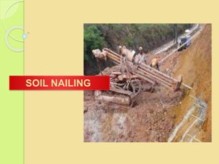
2. Soil nail as stabilization measure for
distressed slopes and for new very steep
cut slopes has the distinct advantage of
strengthening the slope without excessive
earthworks to provide construction access
and working space associated with
commonly used retaining system such as
reinforced concrete wall, reinforced soil
wall, etc. In addition, due to its rather
straightforward construction method and is
relatively maintenance free.
3. Stabilization of existing retaining wall
Tunnels excavations in unstable
slopes
Steep cutting stabilizations
Stabilizing of over steep existing embankments
Stabilization of highway and roadway cut slopes
temporary excavation shoring
Provide long term stability to existing concrete
structures without demolition and rebuilding costs
4.
5. Ground Condition
a) Residual soil and weathered
rocks
b) Stiff cohesive soils such
as clayey silts and other soils
that is not prone to creep
deformation.
c) Dense sand and gravel with
some cohesive properties.
d) Ground conditions located
above the ground water table
(GWT).
a) Soft to very soft fine-
grained soils, Loose clean
granular sand
b) Soils with high
groundwater, .
c) Organic soils
d) Highly fractured rocks with
open joints or voids due to
problem in grouting.
7. 3.2 Basic Elements of a Soil-nailed
System
a) Steel
bar-
b) Centralizers-
c) Grout
e) Hex
nut
f) Temporary and
Permanent Facing-
g) Drainage
System-
d) Nail
head-
8.
9.
10. 4 . advantage of soil nail
It is suitable for cramped sites with difficult
access.
It can easily cope with site constraints and
variations in ground conditions encountered
during construction,.
it causes less environmental impact.
There could be time and cost savings .
The failure mode of a soil-nailed system is
likely to be ductile, thus providing warning
signs before failure.
11. Disadvantages :
1. Nail encroachment to retained
ground rendering unusable
underground space,
2. Less suitable for course
grained soil and soft clayey soil.
3. Lower mobilised nail strength
at lower rows of nailing,
4. Suitable only for excavation
above groundwater.
12. (a)The presence of utilities, underground
structures
(b)Permission has to be obtained from the
owners of the adjacent land for the installation of
soil nails beyond the lot boundary.
(f)Long soil nails are difficult to install, and thus
the soil nailing technique may not be
appropriate for deep-seated landslides and
large slopes.
13. (h)Because soil nails are not prestressed,
mobilisation of soil-nail forces will be
accompanied by ground deformation. The
effects on nearby structures, facilities or
services may have to be considered,
particularly in the case of soil-nailed
excavations.
14. 6 . PRINCIPLES OF A SOIL-NAILED SYSTEM
6.1 FUNDAMENTAL MECHANISM OF A SOIL-NAILED
SYSTEM
The effect of soil nailing is to improve the stability of
slope or excavation through :
Increasing the normal force on shear plane and
hence increase the shear resistance along slip
plane in friction soil.
Reducing the driving force along slip plane both
in friction and cohesive soil In soil nailing.
Soil nail head and facing provides containment
effect to limit the deformation near slope surface.
15. The internal stability of a soil- nailed system
is usually assessed using a two-zone model,
namely the active zone and the passive zone
(or resistant zone).
The active zone is the region in front of the
potential failure surface, where it has a
tendency to detach from the soil-nailed
system.
The passive zone is the region behind the
potential failure surface, where it remains
more or less intact.
The soil nails act to tie the active zone to
the passive zone.
16.
17. These points must be noted for
installation of soil nails
1. Soil Nails must penetrate beyond the slip
plane into the passive zone typically for 4 to
5m.
2. The spacing of soil nails in horizontal or
vertical direction must be related to strength of
the soil
3. Soil nailing should start immediately after
excavation.
4. Any delay in nailing may lead to collapse of
soil slope
18. 7 . SITE INVESTIGATION AND TESTING
which normally proceed in stages:
(i) desk study,
(ii) site reconnaissance,
(iii) collection of field data including
ground investigation and laboratory
testing
(iv) follow-up investigation and
design review during construction
20. CONSTRUCTION
Construction Sequence
Excavate Initial Small Cut is excavated
before the first row nail installation which
is typically about 1to 2 m.The excavated
face should be smooth so as to minimize
shotcrete quantities.
Drill Hole for Nail Holes are drilled at
required location with suitable length
and inclination.
Install and Grout Nail With the help of
centralizers, nails are properly placed
(centered) in the drill holes.
21. Place Drainage System To control
seepage
Place construction facing
temproray( install bearing plates
Steel and securing nut are placed
at each nail head) .
Repeat Process to final grade .
Place final facing For long term
stability reason and durability
reason, a CIP concrete facing is
used. Precast concrete can also be
used as final facing for soil nail
22.
23.
24. . DESIGN OF A SOIL-NAILED
SYSTEM
.3.Engineering
programs used
in designing soil
nailing
.2 Design method
steps
1DESIGN
CONSIDERATION
S
Stability
.
Service
ability
Durability
.
Economi
c
Consider
ations.
Environme
ntal
Considerati
ons.
25. 1. SNAIL-plus computer program
2. GOLDNAIL computer program
3. Geo-Studio computer program
28. 1-external failure mode
External failure modes refer to the
development of potential failure surfaces
passing through or behind the soil nails .For
external failure modes, the soil nail wall
mass is generally treated as a block.
global failure mode
sliding failure mode
bearing failure mode
29.
30. a- Global Stability
This failure is induced in the soil, the nail
and the injection material because the
fixed wall does not bear the impeded loads
and this type of failure depends on both the
tensile strength and the length of the nail
and also on the amount of bonding between
the soil and the nail.
31.
32. It is the failure that occurs in the soil, the nail,
or the substance used in the injection due to
the intolerance of the imposed loads and
depends on the tensile strength, the length of
the nail and the bonding material, as shown
in the figure
2- Internal Failure modes
33. a-Pullout Failure
It is the failure that occurs along the line of contact
between the nail and the substance used in the
injection, and usually results from insufficient
strength of the substance used in injection or that
the length of the nail is not sufficient.
several factors control it:
location of the failure surface depended on soil
type
Drill diameter and method of fixing nails
Friction surface area.
34. b-Tensile Failure of Nail
It is the failure that occurs due to
insufficient tensile strength in the
material used for the nail. Where the
tensile force is generated in the nail
fixed in the soil in the passive area and
extends to the nail head
35. (a) Failure of Ground around
Soil Nails (b) Soil-nail Head Bearing
Failure
(c) Local Failure between
Soil Nails
(d) Tensile Failure of Soil Nails (e) Pullout Failure at (f) Bending or Shear
Ground-grout Interface Failure of Soil Nails
(or Grout-reinforcement
Interface)
(g) Structural Failure and Connection
Failure of Soil-nail Head
(h) Structural Failure and Connection
Failure of Facing
Figure 8.2 Potential Internal Failure Modes of a Soil-nailed System
36. 3- Facing Failure
The most common and likely failure forms of a
facing are when the thickness of the concrete
used is low or the amount of reinforcement used
on the facing is small.
The most common types of failure are
• Due to the high
curvature of the face, whether permanent or
temporary
• It occurs around the
head of the nail whether permanent or
temporary
• As a
37. Steps to design an earthen wall installed using nails with depend on
FHWA,2003
38. 1.Soil wall height obtained from field (H) = 7m
2.Density of the soil obtained from the field Ճm= 18
KNm3
3.Soil cohesion and angle of friction obtained from
the field = 42 , 25
4. SH & SV Between the soil nails Within the range
specified in the approved standard SH * SV <= 4
m2.
SV = 1.25m
SH = 1.25m
39. 5.Calculate the area of influencen=
1.25*1.25 = 1.56 m2 <= 4 (FHWA)
6.Soil Nail pattern on Wall Face, and it
turned out square
7.Soil Nail Inclination(i) = 15
8. Angle of face batter α= 0
9. back slope angle β=0
10.Nail length (L1 = 0.7-1.2H). FHWA
L= 0.7 * 7 = 4.9 m
40.
41. The length of the nail in the lower rows
should not be less than 0.5 H
Nails of irregular length should be used
when layers of soil are of different
conditions.
When using different lengths of nails, the
length of the nails in the upper rows
should be longer than the length of the
nails in the lower rows in order to reduce
42. 11.Select the Drillhole Diameter which ranges between (100-200)
OR (100-300) .(FHWA)
Assume DDH=150mm
12. Determine the values of safety factors and failure patterns = 2
from table
13. The ultimate bond strength ( qu) = 50 kpa from table
14. The allowable bond strength
qa = 25 kpa
F.SP : pullout Resistance
43.
44. 15. (Normalized Bond Strength) μ
μ= (qa . DDH)/( γm . SH . SV) =
0.133
16. .The Normalized cohesion c*
c*=c/γ . H =0.33
17.Find a value (L/H) from the
value μ
= 1.15 from fig
Angle of face batter α=
0
back slope angle β=0
47. 20.Find Soil Cohesion correction
C2L=0.85
21. Find (FSG) Global factor of Safety
C3L=0.52 X 1.35+0.30= 1.00 ≥ 0.85
48. 22. Find Length of Soil Nail
23. Correction ( t max-s ) for drill diameter
• C1F=1.47
• Soil Cohesion :
C2F= -4.0 X C* + 1.09 ≥ 0.85
C2F= -4.0 X 0.33 + 1.09 = -0.23 < 0.85
Use C2F= 0.85
t max-s = C1F X C2F X t max-s
t max-s = 1.47 X 0.85 X 0.22 = 0.27
49. 24. The maximum design nail force:
Tmax-s=γ . H . Sv .SH . t max-s
Tmax-s=18 X 7 X 1.25 X 1.25 X 0.27= 53.15 KN
25. F.ST=1.8
The nail tensile capacity RT
RT= F.ST * T max-s =1.8 X 53.15=95.67 KN
The necessary nail bar cross-sectional area
(AT):
AT=(T max-s X F.ST)/fy = RT/ fy
AT =53.15 X 1.8/517 = 0.185m2=185mm2
Fy=517 MPa
26. Facing Design:T0 = T max-s[0.6+0.2(Sv -1)]
T0 =53.15[0.6+0.2(1.25-1)]= 34.55 KN
56. Discuss the results
From FHWA the minimum F.SG
= 1.35
Through the study of multiple
cases of (i , SH=SV , ϕ)
i = 10 , 15 , 20
SH=SV = 1 , 1.25
Φ = 25
57.
58.
59. Recommendations are for reference only :
• See the design method in FHWA,2003 Extensively It includes
a comprehensive design method for soil nailig ,
• British Standard BS 8006:1995 code of practice for
strengthened reinforcement soils and other fills.
• British Standard BS 8081:1989 code of parametric for ground
Anchorage.
• https://gnpgroup.com.my/wp-
content/uploads/2017/03/2006_06.pdf
• رساله
الطالبه
محمد جيهان
الحيالي
,
خليل احمد امينه الست اشراف
,
الموصل جامعه
,
2020
60. summary
a soil nailing is one of the recent in situ techniques used for soil
improvement and in stabilizing slopes .my search include applications (
Stabilization of highway and roadway embankments and cut slopes Tunnel
portals in unstable and steep stratified slopes).
We also covered fundamentals of a soil-nailed system ( installation
methods .Basic Elements of a Soil-nailed System )
We mentioned a advantages of soil nail and limitations of The soil nailing
technique and study .
then studied site investigation and testing Which includes buildability ,
durability of soil nails and Soil aggressivity and
we studied design of soil nailed Which includes tow methods Which
manual depends on fhwa and Engineering programs used in designing soil
nailing (snail -plus computer program goldnail computer program geo
studio computer program)
monitoring and maintenance
finally we studied construction and