SlideShare ist ein Scribd-Unternehmen logo
1 von 11
Downloaden Sie, um offline zu lesen
2001 GENERAL MOTORS
Saturn L-Series
BUZZERS, RELAYS & TIMERS
BUZZERS, RELAYS & TIMERS LOCATION
CIRCUIT PROTECTION DEVICES
CIRCUIT PROTECTION DEVICES LOCATION
CONTROL UNITS
CONTROL UNITS LOCATION
Component Location
A/C Relay In underhood fuse block (UHFB).
Air Pump Relay (2.2L California) In underhood fuse block (UHFB).
DRL Relay In underhood fuse block (UHFB).
DR Unlock Relay In right instrument panel fuse block (RIPFB).
Fog Lamp Relay In right instrument panel fuse block (RIPFB).
Fuel Pump Relay In underhood fuse block (UHFB).
Horn Relay In underhood fuse block (UHFB).
IGN 3 Relay In left instrument panel fuse block (LIPFB).
Lock Relay In right instrument panel fuse block (RIPFB).
Main Relay (3.0L) In underhood fuse block (UHFB).
Mirror Relay In right instrument panel fuse block (RIPFB).
Rear Defogger Relay In left instrument panel fuse block (LIPFB).
Rear Wiper Relay In underhood fuse block (UHFB).
Unlock Relay In right instrument panel fuse block (RIPFB).
Window Relay In right instrument panel fuse block (RIPFB).
Wiper Relay In underhood fuse block (UHFB).
Component Location
Left Instrument Panel Fuse Block (LIPFB) Behind left kick panel. See Fig. 5 .
Right Instrument Panel Fuse Block (RIPFB) Behind right kick panel. See Fig. 5 .
Underhood Fuse Block (UHFB) Left side of engine compartment. See Fig. 5 .
Component Location
Body Control Module (BCM) Mounted to top of glove box. See Fig. 5 .
Cooling Fan Control Unit Near battery.
Electronic Brake Traction Control Module
(EBTCM)
At left rear of engine compartment.
Electronic Ignition (EI) Module (2.2L) On top of engine, attached to ignition coil housing.
2001 Saturn L300
2001 GENERAL MOTORS Saturn L-Series
2001 Saturn L300
2001 GENERAL MOTORS Saturn L-Series
steve
Monday, May 09, 2011 11:31:30 AM Page 1 © 2006 Mitchell Repair Information Company, LLC.
steve
Monday, May 09, 2011 11:31:37 AM Page 1 © 2006 Mitchell Repair Information Company, LLC.
MOTORS
MOTORS LOCATION
SENDING UNITS & SENSORS
SENDING UNITS & SENSORS LOCATION
See Fig. 1 .
Electronic Ignition (EI) Module (1, 3, 5 Coil) (3.0L) Under right side of upper intake manifold runner.
See Fig. 4 .
Electronic Ignition (EI) Module (2, 4, 6 Coil) (3.0L) Under left side of upper intake manifold runner. See
Fig. 4 .
Engine Control Module (ECM) (3.0L) On top right rear of engine. See Fig. 5 .
Powertrain Control Module (PCM) (2.2L) Behind passenger side air bag. See Fig. 5 .
Sensing & Diagnostic Module (SDM) Under rear of floor console.
Transaxle Control Module (TCM) (3.0L) At right rear corner of engine compartment, behind
strut tower.
Wheel Speed Signal Conditioner Module (2.2L) Behind left side of dash, above hood release.
Component Location
Air Pump (2.2L) On left side of engine, near starter.
Blower Motor On HVAC assembly.
Brake Pressure Modulator Valve (BPMV) On electronic brake traction control module.
Engine Cooling Fan 1 (Puller) Behind radiator.
Engine Cooling Fan 2 (Pusher) On front of A/C condenser.
Front Wiper Motor Below left side of windshield.
Fuel Tank Unit On top of fuel tank.
Heater Water Pump (3.0L) On right side of engine.
Idle Air Control Motor (2.2L) On throttle body.
Mode Door Motor On HVAC assembly.
Rear Wiper Motor (Wagon) In center of liftgate, behind trim.
Recirculation Door Motor On HVAC assembly.
Throttle Control Module (3.0L) On throttle body. See Fig. 3 .
Washer Pump On rear of washer pump reservoir.
Component Location
Accelerator Pedal Position Sensor (3.0L) On accelerator pedal linkage arm.
A/C Pressure Sensor In A/C high side pressure line.
Camshaft Position (CMP) Sensor (3.0L) On top left front of engine. See Fig. 4 .
Crankshaft Position (CKP) Sensor (2.2L) On left side of engine block, above starter. See Fig.
1 .
Crankshaft Position (CKP) Sensor (3.0L) On left rear side of engine, behind oil filter. See Fig.
4 .
2001 Saturn L300
2001 GENERAL MOTORS Saturn L-Series
steve
Monday, May 09, 2011 11:31:30 AM Page 2 © 2006 Mitchell Repair Information Company, LLC.
SOLENOIDS & SOLENOID VALVES
SOLENOIDS & SOLENOID VALVES LOCATION
Engine Coolant Temperature (ECT) Sensor (2.2L) On thermostat housing. See Fig. 2 .
Engine Coolant Temperature (ECT) Sensor (3.0L) In lower coolant passage of left cylinder head. See
Fig. 4 .
Front Wheel Speed Sensor (Left/Right) On steering knuckle.
Fuel Tank Unit On top of fuel tank.
Heated Oxygen Sensor (HO2S) Bank 1 Sensor 1
(3.0L)
On right exhaust manifold. See Fig. 3 .
Heated Oxygen Sensor (HO2S) Bank 1 Sensor 2
(3.0L)
In exhaust system, downstream of right pup
converter.
Heated Oxygen Sensor (HO2S) Bank 2 Sensor 1
(3.0L)
On left exhaust manifold. See Fig. 4 .
Heated Oxygen Sensor (HO2S) Bank 2 Sensor 2
(3.0L)
In exhaust system, downstream of left pup
converter.
Heated Oxygen Sensor (HO2S) Sensor 2 (2.2L) Behind catalytic converter.
Intake Air Temperature (IAT) Sensor (2.2L) In air intake passage of air induction system.
Knock Sensor (2.2L) On engine block, under intake manifold. See Fig. 1 .
Knock Sensor (Cyl. 1, 3, 5) (3.0L) On right side of engine, below exhaust manifold.
See Fig. 3 .
Knock Sensor (Cyl. 2, 4, 6) (3.0L) On left side of engine, below exhaust manifold. See
Fig. 4 .
Low Coolant Level Sensor On bottom of coolant surge tank.
Manifold Absolute Pressure (MAP) Sensor (2.2L) On intake manifold. See Fig. 1 .
Manifold Absolute Pressure (MAP) Sensor (3.0L) On intake manifold. See Fig. 3 .
Mass Airflow (MAF) Sensor (3.0L) On air intake duct.
Output Speed Sensor On right side of transaxle.
Oxygen Sensor 1 (O2S-1) (2.2L) On exhaust manifold. See Fig. 2 .
Rear Wheel Speed Sensor (Left/Right) On hub/bearing assembly.
Side Impact Sensor (Left/Right) On respective lower "B" pillar.
Throttle Position Sensor (2.2L) On throttle body. See Fig. 1 .
Component Location
Air Pump Solenoid (2.2L) Right rear of engine, near thermostat housing.
Decklid Release Solenoid/Ajar Switch At center rear of rear compartment lid.
EGR Solenoid (3.0L) On top right front of engine. See Fig. 3 .
EVAP Purge Solenoid At right side of engine compartment, forward of
strut tower.
EVAP Vent Solenoid At upper end of fuel filler pipe, in right rear wheel
opening.
Fuel Tank Filler Door Lock Actuator At right rear of cargo area, behind trim.
2001 Saturn L300
2001 GENERAL MOTORS Saturn L-Series
steve
Monday, May 09, 2011 11:31:30 AM Page 3 © 2006 Mitchell Repair Information Company, LLC.
SWITCHES
SWITCHES LOCATION
MISCELLANEOUS
MISCELLANEOUS LOCATION
CONNECTORS
CONNECTORS LOCATION
Intake Plenum Switchover Solenoid (3.0L) In intake manifold. See Fig. 3 .
Parklock Switch/BTSI Solenoid At base of selector lever.
Component Location
Back-Up Lamp Switch (M/T) On top rear of transaxle.
Brake/Cruise Switch On brake pedal bracket.
Cruise Clutch Switch On clutch pedal bracket.
Decklid Release Solenoid/Ajar Switch At center rear of rear compartment lid.
Driver Seat Belt Switch In driver's seat belt buckle.
Low Brake Fluid Switch In master cylinder reservoir.
Oil Pressure Switch (2.2L) On engine block, near oil filter. See Fig. 1 .
Oil Pressure Switch (3.0L) On oil pump housing, on lower front of engine.
Parklock Switch/BTSI Solenoid At base of selector lever.
Stoplight Switch On brake pedal bracket.
Transaxle Range Switch On top of transaxle.
Component Location
A/C Diode In underhood fuse block (UHFB).
Blower Motor Resistors On right side of HVAC assembly.
Data Link Connector (DLC) Lower left side of dash.
Ignition Coils (2.2L) On top of engine. See Fig. 1 .
RR Compressor Diode In left instrument panel fuse block (LIPFB).
Component Location
Body To Courtesy Light Jumper (Left) (Gray, 2 Pin) In left front door.
Body To Courtesy Light Jumper (Right) (Gray, 2
Pin)
In right front door.
Body To Headliner (Black, 12 Pin) Behind upper right side of dash.
Body To Left Door Jumper No. 1 (Black, 2 Pin) In left front door.
Body To Left Door Jumper No. 2 (Black, 8 Pin) In left front door.
Body To Left Door Jumper No. 3 (Black, 6 Pin) In left front door.
Body To Right Door Jumper No. 1 (Black, 2 Pin) In right front door.
2001 Saturn L300
2001 GENERAL MOTORS Saturn L-Series
steve
Monday, May 09, 2011 11:31:30 AM Page 4 © 2006 Mitchell Repair Information Company, LLC.
GROUNDS
GROUNDS LOCATION
COMPONENT LOCATION GRAPHICS
Body To Right Door Jumper No. 2 (Black, 10 Pin) In right front door.
CD Body To I/P (Blue, 10 Pin) Near right instrument panel fuse block (RIPFB).
Console Jumper To I/P (Black, 6 Pin) Below center console.
Decklid To Body (Black, 8 Pin) At left side of luggage compartment.
Electronic Brake Traction Control Module Jumper
To Body (Black, 4 Pin)
Near middle of rear suspension assembly.
EVAP Solenoid Jumper To Body (Black, 2 Pin) Near filler neck.
Fuel Tank Jumper To Body (Black, 8 Pin) Near middle of rear suspension assembly.
HVAC Module Jumper (Black, 12 Pin) Behind HVAC module.
Injector Jumper To Engine (2.2L) (Black, 8 Pin) On top of engine.
I/P To Body (Left) (Black, 12 Pin) Near left instrument panel fuse block (LIPFB).
I/P To Body (Right) (White, 16 Pin) Near right instrument panel fuse block (RIPFB).
Premium Sound Jumper To Body (Black, 6 Pin) Near left instrument panel fuse block (LIPFB).
Premium Sound Jumper To Radio (Gray, 24 Pin) Behind radio.
Rear Door Jumper To Body (Left) (Black, 15 Pin) At bottom of left "B" pillar.
Rear Door Jumper To Body (Right) (Black, 15 Pin) At bottom of right "B" pillar.
Component Location
Engine Ground Splice Pack Near center of engine compartment. See Fig. 6 .
I/P Ground Splice Pack (1) At left rear of engine compartment. See Fig. 6 .
I/P Ground Splice Pack (2) At left rear of engine compartment. See Fig. 6 .
Left Forward Light Ground Splice Pack On front of left front fender. See Fig. 6 .
Rear Ground Splice Pack At left rear of luggage compartment. See Fig. 6 .
Right Body Ground Splice Pack Near rear of center console. See Fig. 6 .
NOTE: Figures may show multiple component locations. Refer to appropriate table for
proper figure references.
2001 Saturn L300
2001 GENERAL MOTORS Saturn L-Series
steve
Monday, May 09, 2011 11:31:30 AM Page 5 © 2006 Mitchell Repair Information Company, LLC.
Fig. 1: Left Front Of Engine (2.2L)
Courtesy of GENERAL MOTORS CORP.
2001 Saturn L300
2001 GENERAL MOTORS Saturn L-Series
steve
Monday, May 09, 2011 11:31:30 AM Page 6 © 2006 Mitchell Repair Information Company, LLC.
Fig. 2: Right Rear Of Engine (2.2L)
Courtesy of GENERAL MOTORS CORP.
2001 Saturn L300
2001 GENERAL MOTORS Saturn L-Series
steve
Monday, May 09, 2011 11:31:30 AM Page 7 © 2006 Mitchell Repair Information Company, LLC.
Fig. 3: Right Rear Of Engine (3.0L)
Courtesy of GENERAL MOTORS CORP.
2001 Saturn L300
2001 GENERAL MOTORS Saturn L-Series
steve
Monday, May 09, 2011 11:31:30 AM Page 8 © 2006 Mitchell Repair Information Company, LLC.
Fig. 4: Left Rear Of Engine (3.0L)
Courtesy of GENERAL MOTORS CORP.
2001 Saturn L300
2001 GENERAL MOTORS Saturn L-Series
steve
Monday, May 09, 2011 11:31:30 AM Page 9 © 2006 Mitchell Repair Information Company, LLC.
Fig. 5: Vehicle Overview
Courtesy of GENERAL MOTORS CORP.
2001 Saturn L300
2001 GENERAL MOTORS Saturn L-Series
steve
Monday, May 09, 2011 11:31:30 AM Page 10 © 2006 Mitchell Repair Information Company, LLC.
Fig. 6: Vehicle Overview
Courtesy of GENERAL MOTORS CORP.
2001 Saturn L300
2001 GENERAL MOTORS Saturn L-Series
steve
Monday, May 09, 2011 11:31:30 AM Page 11 © 2006 Mitchell Repair Information Company, LLC.

Weitere ähnliche Inhalte

Was ist angesagt?

Manual serviço c 100 biz c-100 biz es c-100 biz+ (2002) - 00 x6b-gce-763 diag...
Manual serviço c 100 biz c-100 biz es c-100 biz+ (2002) - 00 x6b-gce-763 diag...Manual serviço c 100 biz c-100 biz es c-100 biz+ (2002) - 00 x6b-gce-763 diag...
Manual serviço c 100 biz c-100 biz es c-100 biz+ (2002) - 00 x6b-gce-763 diag...
Thiago Huari
 
Nissan forklift internal combustion 1 d2 series service repair manual
Nissan forklift internal combustion 1 d2 series service repair manualNissan forklift internal combustion 1 d2 series service repair manual
Nissan forklift internal combustion 1 d2 series service repair manual
ufjjjsekkmdm
 
MANUAL ENGINE 1/2KD-FTV TOYOTA SISTEMA COMNON RAIL
MANUAL ENGINE 1/2KD-FTV TOYOTA SISTEMA COMNON RAILMANUAL ENGINE 1/2KD-FTV TOYOTA SISTEMA COMNON RAIL
MANUAL ENGINE 1/2KD-FTV TOYOTA SISTEMA COMNON RAIL
Inês Krug
 
Manaul de serviço ms cbx250 (2001) luzes indicadores
Manaul de serviço ms cbx250 (2001) luzes indicadoresManaul de serviço ms cbx250 (2001) luzes indicadores
Manaul de serviço ms cbx250 (2001) luzes indicadores
Thiago Huari
 

Was ist angesagt? (20)

CASE 1010 GRAIN HEADER parts catalog
CASE 1010 GRAIN HEADER parts catalogCASE 1010 GRAIN HEADER parts catalog
CASE 1010 GRAIN HEADER parts catalog
 
Manual serviço c 100 biz c-100 biz es c-100 biz+ (2002) - 00 x6b-gce-763 diag...
Manual serviço c 100 biz c-100 biz es c-100 biz+ (2002) - 00 x6b-gce-763 diag...Manual serviço c 100 biz c-100 biz es c-100 biz+ (2002) - 00 x6b-gce-763 diag...
Manual serviço c 100 biz c-100 biz es c-100 biz+ (2002) - 00 x6b-gce-763 diag...
 
trabajo de lamultima tarea.docx
trabajo de lamultima tarea.docxtrabajo de lamultima tarea.docx
trabajo de lamultima tarea.docx
 
Diagramas atos
Diagramas atosDiagramas atos
Diagramas atos
 
2005-2010 Ford Mustang Electrical Wiring Diagrams
2005-2010 Ford Mustang Electrical Wiring Diagrams2005-2010 Ford Mustang Electrical Wiring Diagrams
2005-2010 Ford Mustang Electrical Wiring Diagrams
 
Nissan forklift internal combustion 1 d2 series service repair manual
Nissan forklift internal combustion 1 d2 series service repair manualNissan forklift internal combustion 1 d2 series service repair manual
Nissan forklift internal combustion 1 d2 series service repair manual
 
Al4 oil change
Al4 oil changeAl4 oil change
Al4 oil change
 
Esquema elétrico renault master 2.5
Esquema elétrico renault master 2.5Esquema elétrico renault master 2.5
Esquema elétrico renault master 2.5
 
1008 manuals 23032012
1008 manuals   230320121008 manuals   23032012
1008 manuals 23032012
 
3.3 e olss control valve
3.3 e olss control valve3.3 e olss control valve
3.3 e olss control valve
 
Tabela de Códigos de Falhas OBD2 P0001 A P18273
Tabela de Códigos de Falhas OBD2 P0001 A P18273Tabela de Códigos de Falhas OBD2 P0001 A P18273
Tabela de Códigos de Falhas OBD2 P0001 A P18273
 
MANUAL ENGINE 1/2KD-FTV TOYOTA SISTEMA COMNON RAIL
MANUAL ENGINE 1/2KD-FTV TOYOTA SISTEMA COMNON RAILMANUAL ENGINE 1/2KD-FTV TOYOTA SISTEMA COMNON RAIL
MANUAL ENGINE 1/2KD-FTV TOYOTA SISTEMA COMNON RAIL
 
Hyundai D4DD engine manual
Hyundai D4DD engine manualHyundai D4DD engine manual
Hyundai D4DD engine manual
 
Manual volvo
Manual volvoManual volvo
Manual volvo
 
Manaul de serviço ms cbx250 (2001) luzes indicadores
Manaul de serviço ms cbx250 (2001) luzes indicadoresManaul de serviço ms cbx250 (2001) luzes indicadores
Manaul de serviço ms cbx250 (2001) luzes indicadores
 
Fuel d13
Fuel d13Fuel d13
Fuel d13
 
Toyota corolla 1.6 ecu wiring
Toyota corolla 1.6 ecu wiringToyota corolla 1.6 ecu wiring
Toyota corolla 1.6 ecu wiring
 
WIRING DIAGRAM MAZDA 3 2018.pdf
WIRING DIAGRAM MAZDA 3 2018.pdfWIRING DIAGRAM MAZDA 3 2018.pdf
WIRING DIAGRAM MAZDA 3 2018.pdf
 
Chery orinoco m11-service manual
Chery orinoco m11-service manualChery orinoco m11-service manual
Chery orinoco m11-service manual
 
Manual de serviço nx350 sahara 00 x6b-kas-602 alimenta
Manual de serviço nx350 sahara   00 x6b-kas-602 alimentaManual de serviço nx350 sahara   00 x6b-kas-602 alimenta
Manual de serviço nx350 sahara 00 x6b-kas-602 alimenta
 

Ähnlich wie 2001 electrical component locator

MITSUBISHI FB16N FORKLIFT TRUCKS Service Repair Manual SN:EFB15-20011-UP
MITSUBISHI FB16N FORKLIFT TRUCKS Service Repair Manual SN:EFB15-20011-UPMITSUBISHI FB16N FORKLIFT TRUCKS Service Repair Manual SN:EFB15-20011-UP
MITSUBISHI FB16N FORKLIFT TRUCKS Service Repair Manual SN:EFB15-20011-UP
fujdfjjskefkmem
 
Mitsubishi fb20 cn forklift trucks service repair manual snefb17 20011-up
Mitsubishi fb20 cn forklift trucks service repair manual snefb17 20011-upMitsubishi fb20 cn forklift trucks service repair manual snefb17 20011-up
Mitsubishi fb20 cn forklift trucks service repair manual snefb17 20011-up
fjskekdmmse
 
Mitsubishi fb16 n forklift trucks service repair manual snefb15 20011-up
Mitsubishi fb16 n forklift trucks service repair manual snefb15 20011-upMitsubishi fb16 n forklift trucks service repair manual snefb15 20011-up
Mitsubishi fb16 n forklift trucks service repair manual snefb15 20011-up
fskkkdjskemd
 
P-38 BeCM Body Control ECU Guide.pdf
P-38 BeCM Body Control ECU Guide.pdfP-38 BeCM Body Control ECU Guide.pdf
P-38 BeCM Body Control ECU Guide.pdf
JorgeFrana24
 

Ähnlich wie 2001 electrical component locator (14)

Manual reparacion Jeep Compass - Patriot Limited 2007-2009_Electrical compone...
Manual reparacion Jeep Compass - Patriot Limited 2007-2009_Electrical compone...Manual reparacion Jeep Compass - Patriot Limited 2007-2009_Electrical compone...
Manual reparacion Jeep Compass - Patriot Limited 2007-2009_Electrical compone...
 
98 escort
98 escort98 escort
98 escort
 
Plano electrico D8T.pdf
Plano electrico D8T.pdfPlano electrico D8T.pdf
Plano electrico D8T.pdf
 
Toyota yaris diagrama
Toyota yaris diagramaToyota yaris diagrama
Toyota yaris diagrama
 
98estog1e
98estog1e98estog1e
98estog1e
 
fEc210 b 09
fEc210 b 09fEc210 b 09
fEc210 b 09
 
MITSUBISHI FB16N FORKLIFT TRUCKS Service Repair Manual SN:EFB15-20011-UP
MITSUBISHI FB16N FORKLIFT TRUCKS Service Repair Manual SN:EFB15-20011-UPMITSUBISHI FB16N FORKLIFT TRUCKS Service Repair Manual SN:EFB15-20011-UP
MITSUBISHI FB16N FORKLIFT TRUCKS Service Repair Manual SN:EFB15-20011-UP
 
Mitsubishi fb20 cn forklift trucks service repair manual snefb17 20011-up
Mitsubishi fb20 cn forklift trucks service repair manual snefb17 20011-upMitsubishi fb20 cn forklift trucks service repair manual snefb17 20011-up
Mitsubishi fb20 cn forklift trucks service repair manual snefb17 20011-up
 
Mitsubishi fb16 n forklift trucks service repair manual snefb15 20011-up
Mitsubishi fb16 n forklift trucks service repair manual snefb15 20011-upMitsubishi fb16 n forklift trucks service repair manual snefb15 20011-up
Mitsubishi fb16 n forklift trucks service repair manual snefb15 20011-up
 
12m cat
12m cat12m cat
12m cat
 
null-1.pdf
null-1.pdfnull-1.pdf
null-1.pdf
 
Kenr6099 kenr6099 05-sis
Kenr6099 kenr6099 05-sisKenr6099 kenr6099 05-sis
Kenr6099 kenr6099 05-sis
 
CAT 312.pdf
CAT 312.pdfCAT 312.pdf
CAT 312.pdf
 
P-38 BeCM Body Control ECU Guide.pdf
P-38 BeCM Body Control ECU Guide.pdfP-38 BeCM Body Control ECU Guide.pdf
P-38 BeCM Body Control ECU Guide.pdf
 

Mehr von Jeff Sparks

2005 front suspension
2005 front suspension2005 front suspension
2005 front suspension
Jeff Sparks
 
2005 engine electrical
2005 engine electrical2005 engine electrical
2005 engine electrical
Jeff Sparks
 
2005 engine cooling
2005 engine cooling2005 engine cooling
2005 engine cooling
Jeff Sparks
 
2005 disc brakes
2005 disc brakes2005 disc brakes
2005 disc brakes
Jeff Sparks
 
2005 axle shafts
2005 axle shafts2005 axle shafts
2005 axle shafts
Jeff Sparks
 
2005 antilock brakes
2005 antilock brakes2005 antilock brakes
2005 antilock brakes
Jeff Sparks
 
2004 wiring part 3
2004 wiring part 32004 wiring part 3
2004 wiring part 3
Jeff Sparks
 
2004 wiring part 2
2004 wiring part 22004 wiring part 2
2004 wiring part 2
Jeff Sparks
 
2003 power steering
2003 power steering2003 power steering
2003 power steering
Jeff Sparks
 
2001 drive belt routing
2001 drive belt routing2001 drive belt routing
2001 drive belt routing
Jeff Sparks
 
2000 02 rear suspension
2000 02 rear suspension2000 02 rear suspension
2000 02 rear suspension
Jeff Sparks
 
2000 01 steering column
2000 01 steering column2000 01 steering column
2000 01 steering column
Jeff Sparks
 
2000 01 power steering
2000 01 power steering2000 01 power steering
2000 01 power steering
Jeff Sparks
 
2000 01 engine cooling
2000 01 engine cooling2000 01 engine cooling
2000 01 engine cooling
Jeff Sparks
 
2000 01 axle shafts
2000 01 axle shafts2000 01 axle shafts
2000 01 axle shafts
Jeff Sparks
 

Mehr von Jeff Sparks (20)

2005 front suspension
2005 front suspension2005 front suspension
2005 front suspension
 
2005 engine electrical
2005 engine electrical2005 engine electrical
2005 engine electrical
 
2005 engine cooling
2005 engine cooling2005 engine cooling
2005 engine cooling
 
2005 disc brakes
2005 disc brakes2005 disc brakes
2005 disc brakes
 
2005 axle shafts
2005 axle shafts2005 axle shafts
2005 axle shafts
 
2005 antilock brakes
2005 antilock brakes2005 antilock brakes
2005 antilock brakes
 
2004 wiring
2004 wiring2004 wiring
2004 wiring
 
2004 wiring part 3
2004 wiring part 32004 wiring part 3
2004 wiring part 3
 
2004 wiring part 2
2004 wiring part 22004 wiring part 2
2004 wiring part 2
 
2003 power steering
2003 power steering2003 power steering
2003 power steering
 
2001 fuses
2001 fuses2001 fuses
2001 fuses
 
2001 drive belt routing
2001 drive belt routing2001 drive belt routing
2001 drive belt routing
 
2001 airbag
2001 airbag2001 airbag
2001 airbag
 
2000 02 rear suspension
2000 02 rear suspension2000 02 rear suspension
2000 02 rear suspension
 
2000 01 steering column
2000 01 steering column2000 01 steering column
2000 01 steering column
 
2000 01 hvac
2000 01 hvac2000 01 hvac
2000 01 hvac
 
2000 01 power steering
2000 01 power steering2000 01 power steering
2000 01 power steering
 
2000 01 engine cooling
2000 01 engine cooling2000 01 engine cooling
2000 01 engine cooling
 
2000 01 brakes
2000 01 brakes2000 01 brakes
2000 01 brakes
 
2000 01 axle shafts
2000 01 axle shafts2000 01 axle shafts
2000 01 axle shafts
 

2001 electrical component locator

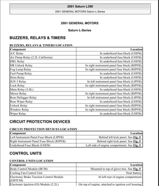
  • 1. 2001 GENERAL MOTORS Saturn L-Series BUZZERS, RELAYS & TIMERS BUZZERS, RELAYS & TIMERS LOCATION CIRCUIT PROTECTION DEVICES CIRCUIT PROTECTION DEVICES LOCATION CONTROL UNITS CONTROL UNITS LOCATION Component Location A/C Relay In underhood fuse block (UHFB). Air Pump Relay (2.2L California) In underhood fuse block (UHFB). DRL Relay In underhood fuse block (UHFB). DR Unlock Relay In right instrument panel fuse block (RIPFB). Fog Lamp Relay In right instrument panel fuse block (RIPFB). Fuel Pump Relay In underhood fuse block (UHFB). Horn Relay In underhood fuse block (UHFB). IGN 3 Relay In left instrument panel fuse block (LIPFB). Lock Relay In right instrument panel fuse block (RIPFB). Main Relay (3.0L) In underhood fuse block (UHFB). Mirror Relay In right instrument panel fuse block (RIPFB). Rear Defogger Relay In left instrument panel fuse block (LIPFB). Rear Wiper Relay In underhood fuse block (UHFB). Unlock Relay In right instrument panel fuse block (RIPFB). Window Relay In right instrument panel fuse block (RIPFB). Wiper Relay In underhood fuse block (UHFB). Component Location Left Instrument Panel Fuse Block (LIPFB) Behind left kick panel. See Fig. 5 . Right Instrument Panel Fuse Block (RIPFB) Behind right kick panel. See Fig. 5 . Underhood Fuse Block (UHFB) Left side of engine compartment. See Fig. 5 . Component Location Body Control Module (BCM) Mounted to top of glove box. See Fig. 5 . Cooling Fan Control Unit Near battery. Electronic Brake Traction Control Module (EBTCM) At left rear of engine compartment. Electronic Ignition (EI) Module (2.2L) On top of engine, attached to ignition coil housing. 2001 Saturn L300 2001 GENERAL MOTORS Saturn L-Series 2001 Saturn L300 2001 GENERAL MOTORS Saturn L-Series steve Monday, May 09, 2011 11:31:30 AM Page 1 © 2006 Mitchell Repair Information Company, LLC. steve Monday, May 09, 2011 11:31:37 AM Page 1 © 2006 Mitchell Repair Information Company, LLC.
  • 2. MOTORS MOTORS LOCATION SENDING UNITS & SENSORS SENDING UNITS & SENSORS LOCATION See Fig. 1 . Electronic Ignition (EI) Module (1, 3, 5 Coil) (3.0L) Under right side of upper intake manifold runner. See Fig. 4 . Electronic Ignition (EI) Module (2, 4, 6 Coil) (3.0L) Under left side of upper intake manifold runner. See Fig. 4 . Engine Control Module (ECM) (3.0L) On top right rear of engine. See Fig. 5 . Powertrain Control Module (PCM) (2.2L) Behind passenger side air bag. See Fig. 5 . Sensing & Diagnostic Module (SDM) Under rear of floor console. Transaxle Control Module (TCM) (3.0L) At right rear corner of engine compartment, behind strut tower. Wheel Speed Signal Conditioner Module (2.2L) Behind left side of dash, above hood release. Component Location Air Pump (2.2L) On left side of engine, near starter. Blower Motor On HVAC assembly. Brake Pressure Modulator Valve (BPMV) On electronic brake traction control module. Engine Cooling Fan 1 (Puller) Behind radiator. Engine Cooling Fan 2 (Pusher) On front of A/C condenser. Front Wiper Motor Below left side of windshield. Fuel Tank Unit On top of fuel tank. Heater Water Pump (3.0L) On right side of engine. Idle Air Control Motor (2.2L) On throttle body. Mode Door Motor On HVAC assembly. Rear Wiper Motor (Wagon) In center of liftgate, behind trim. Recirculation Door Motor On HVAC assembly. Throttle Control Module (3.0L) On throttle body. See Fig. 3 . Washer Pump On rear of washer pump reservoir. Component Location Accelerator Pedal Position Sensor (3.0L) On accelerator pedal linkage arm. A/C Pressure Sensor In A/C high side pressure line. Camshaft Position (CMP) Sensor (3.0L) On top left front of engine. See Fig. 4 . Crankshaft Position (CKP) Sensor (2.2L) On left side of engine block, above starter. See Fig. 1 . Crankshaft Position (CKP) Sensor (3.0L) On left rear side of engine, behind oil filter. See Fig. 4 . 2001 Saturn L300 2001 GENERAL MOTORS Saturn L-Series steve Monday, May 09, 2011 11:31:30 AM Page 2 © 2006 Mitchell Repair Information Company, LLC.
  • 3. SOLENOIDS & SOLENOID VALVES SOLENOIDS & SOLENOID VALVES LOCATION Engine Coolant Temperature (ECT) Sensor (2.2L) On thermostat housing. See Fig. 2 . Engine Coolant Temperature (ECT) Sensor (3.0L) In lower coolant passage of left cylinder head. See Fig. 4 . Front Wheel Speed Sensor (Left/Right) On steering knuckle. Fuel Tank Unit On top of fuel tank. Heated Oxygen Sensor (HO2S) Bank 1 Sensor 1 (3.0L) On right exhaust manifold. See Fig. 3 . Heated Oxygen Sensor (HO2S) Bank 1 Sensor 2 (3.0L) In exhaust system, downstream of right pup converter. Heated Oxygen Sensor (HO2S) Bank 2 Sensor 1 (3.0L) On left exhaust manifold. See Fig. 4 . Heated Oxygen Sensor (HO2S) Bank 2 Sensor 2 (3.0L) In exhaust system, downstream of left pup converter. Heated Oxygen Sensor (HO2S) Sensor 2 (2.2L) Behind catalytic converter. Intake Air Temperature (IAT) Sensor (2.2L) In air intake passage of air induction system. Knock Sensor (2.2L) On engine block, under intake manifold. See Fig. 1 . Knock Sensor (Cyl. 1, 3, 5) (3.0L) On right side of engine, below exhaust manifold. See Fig. 3 . Knock Sensor (Cyl. 2, 4, 6) (3.0L) On left side of engine, below exhaust manifold. See Fig. 4 . Low Coolant Level Sensor On bottom of coolant surge tank. Manifold Absolute Pressure (MAP) Sensor (2.2L) On intake manifold. See Fig. 1 . Manifold Absolute Pressure (MAP) Sensor (3.0L) On intake manifold. See Fig. 3 . Mass Airflow (MAF) Sensor (3.0L) On air intake duct. Output Speed Sensor On right side of transaxle. Oxygen Sensor 1 (O2S-1) (2.2L) On exhaust manifold. See Fig. 2 . Rear Wheel Speed Sensor (Left/Right) On hub/bearing assembly. Side Impact Sensor (Left/Right) On respective lower "B" pillar. Throttle Position Sensor (2.2L) On throttle body. See Fig. 1 . Component Location Air Pump Solenoid (2.2L) Right rear of engine, near thermostat housing. Decklid Release Solenoid/Ajar Switch At center rear of rear compartment lid. EGR Solenoid (3.0L) On top right front of engine. See Fig. 3 . EVAP Purge Solenoid At right side of engine compartment, forward of strut tower. EVAP Vent Solenoid At upper end of fuel filler pipe, in right rear wheel opening. Fuel Tank Filler Door Lock Actuator At right rear of cargo area, behind trim. 2001 Saturn L300 2001 GENERAL MOTORS Saturn L-Series steve Monday, May 09, 2011 11:31:30 AM Page 3 © 2006 Mitchell Repair Information Company, LLC.
  • 4. SWITCHES SWITCHES LOCATION MISCELLANEOUS MISCELLANEOUS LOCATION CONNECTORS CONNECTORS LOCATION Intake Plenum Switchover Solenoid (3.0L) In intake manifold. See Fig. 3 . Parklock Switch/BTSI Solenoid At base of selector lever. Component Location Back-Up Lamp Switch (M/T) On top rear of transaxle. Brake/Cruise Switch On brake pedal bracket. Cruise Clutch Switch On clutch pedal bracket. Decklid Release Solenoid/Ajar Switch At center rear of rear compartment lid. Driver Seat Belt Switch In driver's seat belt buckle. Low Brake Fluid Switch In master cylinder reservoir. Oil Pressure Switch (2.2L) On engine block, near oil filter. See Fig. 1 . Oil Pressure Switch (3.0L) On oil pump housing, on lower front of engine. Parklock Switch/BTSI Solenoid At base of selector lever. Stoplight Switch On brake pedal bracket. Transaxle Range Switch On top of transaxle. Component Location A/C Diode In underhood fuse block (UHFB). Blower Motor Resistors On right side of HVAC assembly. Data Link Connector (DLC) Lower left side of dash. Ignition Coils (2.2L) On top of engine. See Fig. 1 . RR Compressor Diode In left instrument panel fuse block (LIPFB). Component Location Body To Courtesy Light Jumper (Left) (Gray, 2 Pin) In left front door. Body To Courtesy Light Jumper (Right) (Gray, 2 Pin) In right front door. Body To Headliner (Black, 12 Pin) Behind upper right side of dash. Body To Left Door Jumper No. 1 (Black, 2 Pin) In left front door. Body To Left Door Jumper No. 2 (Black, 8 Pin) In left front door. Body To Left Door Jumper No. 3 (Black, 6 Pin) In left front door. Body To Right Door Jumper No. 1 (Black, 2 Pin) In right front door. 2001 Saturn L300 2001 GENERAL MOTORS Saturn L-Series steve Monday, May 09, 2011 11:31:30 AM Page 4 © 2006 Mitchell Repair Information Company, LLC.
  • 5. GROUNDS GROUNDS LOCATION COMPONENT LOCATION GRAPHICS Body To Right Door Jumper No. 2 (Black, 10 Pin) In right front door. CD Body To I/P (Blue, 10 Pin) Near right instrument panel fuse block (RIPFB). Console Jumper To I/P (Black, 6 Pin) Below center console. Decklid To Body (Black, 8 Pin) At left side of luggage compartment. Electronic Brake Traction Control Module Jumper To Body (Black, 4 Pin) Near middle of rear suspension assembly. EVAP Solenoid Jumper To Body (Black, 2 Pin) Near filler neck. Fuel Tank Jumper To Body (Black, 8 Pin) Near middle of rear suspension assembly. HVAC Module Jumper (Black, 12 Pin) Behind HVAC module. Injector Jumper To Engine (2.2L) (Black, 8 Pin) On top of engine. I/P To Body (Left) (Black, 12 Pin) Near left instrument panel fuse block (LIPFB). I/P To Body (Right) (White, 16 Pin) Near right instrument panel fuse block (RIPFB). Premium Sound Jumper To Body (Black, 6 Pin) Near left instrument panel fuse block (LIPFB). Premium Sound Jumper To Radio (Gray, 24 Pin) Behind radio. Rear Door Jumper To Body (Left) (Black, 15 Pin) At bottom of left "B" pillar. Rear Door Jumper To Body (Right) (Black, 15 Pin) At bottom of right "B" pillar. Component Location Engine Ground Splice Pack Near center of engine compartment. See Fig. 6 . I/P Ground Splice Pack (1) At left rear of engine compartment. See Fig. 6 . I/P Ground Splice Pack (2) At left rear of engine compartment. See Fig. 6 . Left Forward Light Ground Splice Pack On front of left front fender. See Fig. 6 . Rear Ground Splice Pack At left rear of luggage compartment. See Fig. 6 . Right Body Ground Splice Pack Near rear of center console. See Fig. 6 . NOTE: Figures may show multiple component locations. Refer to appropriate table for proper figure references. 2001 Saturn L300 2001 GENERAL MOTORS Saturn L-Series steve Monday, May 09, 2011 11:31:30 AM Page 5 © 2006 Mitchell Repair Information Company, LLC.
  • 6. Fig. 1: Left Front Of Engine (2.2L) Courtesy of GENERAL MOTORS CORP. 2001 Saturn L300 2001 GENERAL MOTORS Saturn L-Series steve Monday, May 09, 2011 11:31:30 AM Page 6 © 2006 Mitchell Repair Information Company, LLC.
  • 7. Fig. 2: Right Rear Of Engine (2.2L) Courtesy of GENERAL MOTORS CORP. 2001 Saturn L300 2001 GENERAL MOTORS Saturn L-Series steve Monday, May 09, 2011 11:31:30 AM Page 7 © 2006 Mitchell Repair Information Company, LLC.
  • 8. Fig. 3: Right Rear Of Engine (3.0L) Courtesy of GENERAL MOTORS CORP. 2001 Saturn L300 2001 GENERAL MOTORS Saturn L-Series steve Monday, May 09, 2011 11:31:30 AM Page 8 © 2006 Mitchell Repair Information Company, LLC.
  • 9. Fig. 4: Left Rear Of Engine (3.0L) Courtesy of GENERAL MOTORS CORP. 2001 Saturn L300 2001 GENERAL MOTORS Saturn L-Series steve Monday, May 09, 2011 11:31:30 AM Page 9 © 2006 Mitchell Repair Information Company, LLC.
  • 10. Fig. 5: Vehicle Overview Courtesy of GENERAL MOTORS CORP. 2001 Saturn L300 2001 GENERAL MOTORS Saturn L-Series steve Monday, May 09, 2011 11:31:30 AM Page 10 © 2006 Mitchell Repair Information Company, LLC.
  • 11. Fig. 6: Vehicle Overview Courtesy of GENERAL MOTORS CORP. 2001 Saturn L300 2001 GENERAL MOTORS Saturn L-Series steve Monday, May 09, 2011 11:31:30 AM Page 11 © 2006 Mitchell Repair Information Company, LLC.