Dc compund motor construction and working
•Als PPTX, PDF herunterladen•
3 gefällt mir•2,748 views

DC Compound motors are popular due do their characteristic of good starting torque and low speed regulation. The are used in pressure blowers, pumps, industrial fan, lathes etc.

Empfohlen
Weitere ähnliche Inhalte
Was ist angesagt?
Was ist angesagt? (20)
Ähnlich wie Dc compund motor construction and working
Ähnlich wie Dc compund motor construction and working (20)
Mehr von Sourabh sharma
Mehr von Sourabh sharma (20)
Kürzlich hochgeladen
Kürzlich hochgeladen (20)
Dc compund motor construction and working
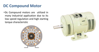
- 1. DC Compound Motor •Dc Compound motors are utilized in many industrial application due to its low speed regulation and high starting torque characteristic
- 2. Construction Stator: • Generally the outer is stationary part that’s why it is called as stator which consist of Frame or yoke inside which pole shoes are bolted projecting Inwards . • Main fields poles (bigger ones) are always in even number or in number of pairs • Inter poles (smaller ones) are also built in even number or in number of pairs • On each pole shoe the cropper or aluminum winding is wound known as field winding which carries the field current to create static magnetic poles on the stator. • In all dc machines Filed winding are wound on stators. DC Compound Motor
- 3. Construction Rotor: • Central rotating part is known as rotor built up of laminated core having multiple number of slots (axially oriented) on outer periphery. • The rotor slots consist of armature conductors are connected to form close type winding. • Winding could be wound in “lap” or “wave” patterns • The complete core is mounted on high grade stainless steel shaft also keyed to it so as to avoid slipping. • The shaft is also mounted with commutator ring made up of multiple number of commutator segments. • From each commutator segments ends of the armature winding are connected. DC Compound Motor
- 4. Related Videos; Click Or Skip to Next Slide
- 5. Main Field Pole Inter-pole Yoke Pole Shoe Armature/ Rotor core Armature winding Commutator Shaft DC Compound Motor Shunt Field Winding Series Field Winding
- 6. Construction • Rotor is placed inside the stator separated by small air gap and free to rotate. • Rotor is supported by the end cover on both side of the motor frame by the help of bearings. • Brushes feeds direct electric current in to the armature winding pressing on commutator segment. • Number of brushes are always equal to number of main poles • Four carbon brushes are in this case of four pole compound motor • brushes are always placed at inter polar region. DC Compound Motor
- 7. N S N S Working • It works on the principle of Lorentz Law, which states that “the current carrying conductor placed in a magnetic field experience a force. • Magnetic Field is produce by the main field poles. • All main poles consist of two winding set and out of which one is connected in parallel and another set is connected in series with the main field winding. • Field lines emerges radialy inwards from North Pole and converges in to South Poles placed next to every North Pole. DC Compound Motor
- 8. Working • Simple representation of field winding. • Current enters in to first pole form one end and exit form another terminal from last pole. DC Compound Motor
- 9. Working • Verifying direction of each pole magnet using right hand thumb rule. • Using right hand grip rule DC Compound Motor
- 10. Working • Wiring connection of burses. • Two brushes are given Positive voltage and two are given negative. DC Compound Motor
- 11. Related Videos; Click Or Skip to Next Slide
- 12. DC Shunt Motor Working • When dc current is feed in to the commutator using brushes. • The current flows through the armature/rotor winding in such a way that the coil sides/conductors under the influence of North pole of stator/field carry current in one direction represented by dot in the diagram. • The current flows in the coil side/conductor under the influence of south pole carries current in opposite direction represented by cross in the diagram.
- 14. Working • Verifying the direction of force on the conductors of Left hand side of rotor. • Applying Fleming left hand rule. • Index finger – direction of field • Middle finger – direction of current • Thumb – Gives direction of force DC Compound Motor
- 15. Working • Verifying the direction of force on the conductors of top side of rotor. • Applying Fleming left hand rule. • Index finger – direction of field • Middle finger – direction of current • Thumb – Gives direction of force DC Compound Motor
- 16. Working • Verifying the direction of force on the conductors of right side of rotor. • Applying Fleming left hand rule. • Index finger – direction of field • Middle finger – direction of current • Thumb – Gives direction of force DC Compound Motor
- 17. Working • Verifying the direction of force on the conductors of bottom side of rotor. • Applying Fleming left hand rule. • Index finger – direction of field • Middle finger – direction of current • Thumb – Gives direction of force DC Compound Motor
- 19. Working • After verifying direction of force on all the conductors, it could be conclude that the rotor is getting torque in clock wise direction DC Compound Motor
- 20. DC Compound Motor Connection of windings
- 22. Related Videos; Click Thank You