1. 1
Embedded System Project (521423S)
Tero Vallius
Hannu Rautio
Juha Röning
Computer Engineering Laboratory
Department of Electrical Engineering
University of Oulu
2003
2. 2
Abstract
The goal of this course is to help students understand the world of embedded computer
systems. Usually participants are information and electrical engineering students who
are specialized in software and system design. Most attention has been given to ele-
mentary hardware design skills because these skills are the ones students often lack.
This course is structured as a guided walk through the hardware design process.
This document defines the project topic for spring 2003, gives general guidelines and
course procedures. Additionally major electronics components is proposed and practi-
cal hints are given. The students are encouraged to give feedback for improving both
the course and its material.
The Embedded System Project is related to, but independent of Software Engineering
Project (Ohjelmistotekniikan työ, 521451S) that concentrates on software-hardware
interface.
4. 4
1. Course objectives
The purpose of the Embedded System Project (Sulautettujen järjestelmien työt) course
is to provide you knowledge and hands-on experience in the embedded computer sys-
tem technology. The course is intended to students specializing in software and system
design, giving most attention to hardware design, as understanding in this area is vital
for most embedded software designers. In short, this course is a chance for the very
novices in electronics design to create a simple embedded computer based device and
to learn the maximum from the experience.
You will learn both about design and tools. You will learn to study the components to
fit the various pieces together into a complete system and you will understand the role
of a microcontroller, seeing it as basic building block. In particular, you will concen-
trate on hardware-software interaction, although very little software will be written in
this project. You will learn to design the schematics and layout using Printed Circuit
Board (PCB) tools (e.g. OrCad), although their more advanced functions are not cov-
ered in this course. In the end, you will learn to use an emulator and other microcon-
troller development tools while testing the assembled circuit board you will make.
Admittedly, there is a lot to be learned.
The course is realized as a project-like assignment that requires approximately 120-
160 hours from a team of two students during a single term. There are several topics to
choose from. The topics are divided to three categories: basic topic, optional topics and
own topic. The basic topic is meant for people that are new to the embedded systems.
The basic topic contains only familiar technologies and the teachers are familiar with
the topic, enabling more efficient tutoring. Also some suitable components for the as-
signment have been pre-examined, letting the students to avoid the full exposure to
“navigation” problems, such as selecting, finding, and ordering components. The spec-
ification for this topic is already defined and the basic structure of the work is fixed,
but there are still some degrees of freedom in the design.
The optional topics are meant for students with some interest in embedded systems.
These topics use modern technology and the design is predefined only at high level.
The students create the actual specification by themselves. This specification is then
checked and approved by the teachers. For these topics there are only a few pre-exam-
ined key component proposals, but the students will choose most of the components
themselves. These topics give the students a great freedom of creativity. The teachers
will help with adjusting the specification to be not too difficult but still challenging
enough. The teachers will also help with the component selections and with the design,
but the students have the main responsibility of the design. As some of the components
may be new, they may prove to be non-functional in some designs. This is not a catas-
trophy and these possibilities are taken into account in grading. However, careful plan-
ning and hard trying is still required. The students may also propose their own topic.
These proposals are handled similarly to the optional topic specifications.
We believe a reasonably painless completion of this course requires the following
course background: Digital Design I (Digitaalitekniikka I, 521413A), Computer Engi-
neering I (Tietokonetekniikka I, 521415A), and Computer Engineering II
5. 5
(Tietokonetekniikka II 521419A). In addition, Software Engineering Project (Ohjel-
mistotekniikan työ, 521451S) and Electronic Design course (Elektroniikkasuunnitte-
lun perusteet, 521431A) are useful.
We hope you will assist us in the development of this course by giving your criticism
and hints. The basic topic for spring 2003 is Robot Control Module. You may also
choose one of our optional topics or propose a topic of your own.
6. 6
2 Topic descriptions
2.1 Basic topic: Robot Control Module (RCM)
Your task is to design a control module for a robot. The robot is a simple two wheel
robot that uses two stepper motors for driving. The robot can be programmed to drive
autonomously a certain path. A list of driving commands are first downloaded from a
PC to the robot, after which the robot will drive automatically through the program.
The mechanics of the robot are provided. They include the robot base with two stepper
motors for wheels, bumber switches and an LCD display. The motors, switches and
LCD-display have simple connectors for attaching them to the control module. Figure
of the base will appear to course web pages (http://www.ee.oulu.fi/~terva/
Embedded2003) when ready. The robot base has a space for a standard euro size PCB
(10 x 16 cm) and four holes for attaching the PCB to the base. Thus you need to imple-
ment your control module to a 10 x 16 cm sized PCB and place the holes to correct
places. A footprint for the holes is provided, so you only need to add the footprint to
your PCB to get the holes to their right places.
The control module will be based on an Atmel ATmega series microcontroller. The
students can choose from three choices: Atmega 161, 163 and 323. The control module
is required to contain the following peripherals:
- some external memory for saving the driving commands
- RS232 serial connection for the PC
- some buttons and an LCD display for operating the robot
- driver or amplifier IC:s for interfacing to the stepper motors
- programmer header or programming circuit for programming a real microcontroller
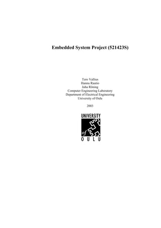
The main connections are presented in figure 1. The minimum requirements for the
RCM system to be built by each group are the following:
1) The driving commands can be uploaded from a PC to the RCM.
2) The robot can autonomously drive the programmed path.
3) The robot will stop when bumper hits an obstacle (optionally tries to avoid the ob-
stacle).
4) The robot has a user interface, which is used with buttons and LCD-display. The UI
is used at least for starting the driving and downloading data from PC.
5) The robot is operable with both battery and external dc-power.
The robot control module must be able to understand at least commands for driving
forward and backwards a length specified in centimeters and turning an angle specified
in degrees. For example a command for driving could be FW25, which takes the robot
forward 25 cm or BW04, which takes it bacwards 4 cm:s. Similarly turning could be
CW50, which turns the robot 50 degrees clockwise or CC24, which turns the robot 24
degrees counter-clockwise.
The command list, which will be uploaded from a PC, will consist of a series of these
commands. For example using commands from the previous example, the list could be:
FW10
CC90
FW50
7. 7
CW90
BW10
CW90
FW50
...
The previous commands are just examples. The groups may use them or create their
own commands. We suggest you use ASCII commands in order to be able to test them
easily with normal terminal programs such as HyperTerminal. However, any com-
mands are allowed, as long as you are able too demonstrate it working.
LCD display
PC
Stepper
Motor
Buttons
RS-232
Robot Control Module
External
Memory
Stepper Bumper
Motor Switches
Figure 1. The main connections of Robot Control Module (RCM)
The robot software will be developed mainly with an emulator environment and using
an external power source. When the software and hardware are about complete, the
emulator will be left out and a real microcontroller will taken into use. Similarly the
external power source will be replaced by a battery. In other words, the final tests and
the demonstration will be made with a real microcontroller and a battery.
The suggested emulator environment for developing the software and testing the im-
plementations is presented in Figure 2. It consists of a PC workstation and a Atmel
ICE50 In Circuit Emulator. The self-made Printed Circuit Board (PCB) is connected
to the pod of the ICE. This is about the only stage in which the ICE can be damaged.
8. 8
Connector pod Emulator cable
Atmel Emulator
ICE50 PC
Your own
PCB
Figure 2. The emulator system hardware for Embedded Systems course.
How to connect the emulator cable:
1. Before connecting your design, turn the power off from the Atmel ICE50. The
PC workstation does not need to be shut down or switched off.
2. Connect the pod into the microprocessor socket of the PCB to be tested very
gently - it is extremely easy to bend the pins of the pod. Always use an extra
socket connected to the pod to avoid damaging it. This way the pod itself stays
in tact even if the pins are bend - only the extra socket has to be replaced.
3. When the ICE50 is properly connected to the target and the host PC, the power
can be turned on. The following procedure is recommended to ensure proper
communication between the ICE50 and AVR Studio.
• Power up ICE50
² Power up target board (PCB)
² Start AVR Studio
Note: The equipment will not be harmed in any way if a different power up se-
quence is used, but since AVR Studio tries to detect peripherals when started, the
ICE50 will not be detected if not powered.
Be sure to switch off all powers before disassembling the system!
If these instructions are followed carefully every time the environment is used, costly
(and time consuming) repairs can be avoided.
If you are unsure about how to use the system, please read the instructions once more,
familiarize yourself with the manuals, and consult the supervisor of your team before
doing something questionable. After you have learned the basic routines, the use of the
system is quite straightforward and easy. However, please remember that everyone has
to start from the beginning sometime.
As the robot is a moving object, the final tests and the demonstration cannot be made
with the emulator, but with a real microcontroller. This requires that the students will
include either a programming header or the circuit to their PCB:s. Tools for uploading
the software to the controller are provided in the laboratory. The flashing software is
PonyProg2000. More information about the programming is found at http://
www.ee.oulu.fi/~terva/Embedded2003/flashing.php.
9. 9
The teams are free to create additional features to their system if they will. These ad-
ditional features affect positively (to a certain extend) to the grading of the team, pro-
vided that the features are useful and working. All the basic features have to be met to
pass the course.
The teams are free to choose any microcontroller environment for their RCM system,
but they are strongly encouraged to use the Atmel ATmega161 microcontroller and the
ICE found from the student laboratory TS139. Before some other architecture is cho-
sen the teams shall consult with the supervisor of their team.
2.2 Optional topics and own topic
The optional topics are available at http://www.ee.oulu.fi/~terva/Embedded2003/top-
ics.php. For these topics the students are recommended to choose their microcontroller
from the ones listed at page http://www.ee.oulu.fi/~terva/Embedded2003/mcus.php.
Some components that may be suitable for different topics can be found at http://
www.ee.oulu.fi/~terva/Embedded2003/components.php.
10. 10
3. General guidelines
As this course is intended to students with software orientation, the question is proba-
bly about the first electronics device you design. Therefore, do not rush, but proceed
in good order, as this will eliminate much of the learning pains.
First, write down the system requirements and sketch your design on paper avoiding
too much detail. The requirements should include the operational sequences of the sys-
tem. Also write down your ideas and calculations, and keep your notes, please. It is im-
portant for yourself to see the progress, because design is an iterative process and you
are likely to review your earlier decisions. Figure 3 shows the major milestones in a
typical small project that combines software and hardware development.
power consumption, operation procedures
environment etc. System requirements
partitioning, Sketch of Sketch of modes, functions,
basic solutions hardware software algorithms, control
Evaluation and simulation
against requirements
schematics and testability
layout Detailed Test
HW-design design considerations
printed wiring board PWB and embedded software
manufacturing assembly Software design
continuity and Simulator
HW functionality HW-tests tests
EEPROM
Integration programming
Figure 3. Typical stages in a small-scale embedded HW/SW-project.
Familiarize yourself with the proposed components. This is necessary before detailed
design can be carried out. Selecting the components, or building blocks, is very time
consuming, unless you have prior experience and know what you are looking for. The
component selection process can be compared to finding pieces to a jigsaw puzzle: you
may approximately know your needs, but you do not know for sure if something you
see fits unless you try it.
11. 11
In the course web page http://www.ee.oulu.fi/~terva/Embedded2003/index.php we list
a handful of key components. Please, remember that the list of the components is just
a suggestion and you can and need to use another components too.
First you are advised to check what components can be found from the store of the lab-
oratory TS102 (Appendix F). More components can be found from component cata-
logues. The ordering of the components is buffered, i.e. orders from a couple of groups
are collected together before sending it out. If you have selected some very special
components you have to find out yourselves the availability. Please, try to follow rea-
sonable budget.
We recommend that in the beginning you should first study the functions of the com-
ponents and make sketches of their use. If you are still not sure how a component
works, it’s a good idea to build a test circuit. Tools for testing are available in the
laboratory TS102.
The example applications presented on the data sheets are very helpful. After a few ex-
ercises your data sheet reading skills have improved substantially. You will then start
seeing solutions and may proceed to the first sketch of the system. Alternatively, if you
have some prior experience, you may first make a rough sketch of the system and then
look for suitable components.
Keep in mind that in this system software works in a close interaction with hardware.
Thus, check every hardware change you make during design against the software func-
tions and system requirements. Check every wire of the components and the timing of
every signal. The first time it is laborious, but you will learn a lot in the process and
will never regret it.
Use the PCB tools after the design has stabilized. Please check the example PCB
project that Mr. Eric Galloix has made from course web page. Try to learn the use of
the tools systematically, because this will speed up your work. It is good practice to
exercise with a simpler toy design. The final implementation and testing phases are
quite rapid, when compared to software design.
Finally, we recommend that you avoid dividing the tasks in the project between the
members of your team on a strict hardware/software basis.
4. Atmel ICE50 In Circuit Emulator system
The Embedded system project is suggested to be built using the on of the Atmel At-
mega series microcontroller, for which an In Circuit Emulator (ICE) can be found from
TS139. The ICE is connected to a PC workstation and all the controlling and develop-
ment software are run under a 32 bit Windows operating system. Detailed instructions
of using the ICE, and the software are found from the manuals, which every team is
suggested to read (the manual is available as a help documents in Atmel AVR Studio
4.x software package, which is freely downloadable at http://www.atmel.com/atmel/
products/prod203.htm). Some overview of the system and its general structure is how-
12. 12
ever presented in this section.
4.1 System hardware
The Atmel ICE50 is designed for developing software for Atmel ATmega series mi-
crocontrollers. It can be used as a stand-alone emulator without user hardware, or as
done in this course, as a microcontroller emulator for debugging and testing self-build
PCBs. The ICE is connected to a PC workstation via a cable and it connects to the mi-
crocontroller socket of the PCB via another cable and a pod (for 40-pin dip socket).
The emulator supports several hardware and program breakpoints, which are useful in
debugging the system. It also provides advanced capabilities for tracing the operation
of the microcontroller, as well the possibility to single-step the program currently per-
formed by the system. The greatest benefit is however the fact that as it emulates the
microcontroller code, that is normally programmed into the internal memory of the mi-
crocontroller, can now be changed on the fly thus significantly reducing the time to
make changes in the software.
4.2 Software development tools
The tools for developing the software needed in the Embedded system project consist
of three main software tools:
• Atmel AVR-studio 4.xx that is used for transferring the program code into the ICE,
as well as debugging and running the program. It includes also a C-level debug-
ging tool and for simulation of the program operation and a complete manual for
using the ICE50. The studio is freely available at http://www.atmel.com/atmel/
products/prod203.htm.
• IAR Embedded Workbench that is used for writing the source code (other text edi-
tors can be used as well), and compiling and linking the software for the target
microcontroller. Optionally students can use GNU AVR-gcc, which is freely avail-
able and suitable for home development.
The usage of these tools is explained in their respective manuals that can be found (and
are to be kept) in room TS139. The basic principle is to develop and test the program
with the IAR tools and transfer it to the target hardware with the AVR-studio, when the
logical structure of the program is done.
All these software tools are installed into the PC workstation connected to the emula-
tor. Another PC workstation for developing software with the IAR tools is also avail-
able. If the team wants to develop software at home, which is also recommend to some
extend, students can use a demonstration system of the IAR Embedded workbench
(available from the Internet at http://www.iar.com/) or GNU AVR-gcc (available at
www.avrfreaks.net).
4.3 General principles of using the ICE
When connecting the self-made board to the pod of the ICE50 special care is to be tak-
13. 13
en. This is about the only stage in which the ICE can be damaged. The following steps
must be followed at all times:
• Turn the power off from the ICE50 before connecting your system to it. The PC
workstation does not have to be shut down or switched off
• Connect the pod into the microprocessor socket of the PCB to be tested very gently
- it is extremely easy to bend the pins of the pod.
• Always use an extra socket connected to the pod to avoid damaging it. This way
the pod itself stays in tact even if the pins are bend - only the extra socket has to be
replaced.
• The power of the self made PCB can be switched on and off any time when the PC
workstation and the ICE are up and running.
• Be sure to switch off all powers before disassembling the system.
If these instructions are followed carefully every time the environment is used costly
(and time consuming) repairs can be avoided.
5. Practical advice
Many of the following hints are based on the personal experiences of the authors and
the experiences from the last years courses. Most of them are warnings. To err is hu-
man and destroying a component due to a design mistake is part of the life.
• The workshop of the department has facilities for producing plated-through holes.
The printed wiring boards (PWBs) are made with a milling cutter (jyrsin), and the
short instructions can be found from course web page http://www.ee.oulu.fi/~terva/
Embedded2003. Please contact to Kirsi Kullaa (SÄ125, tel. 553 2634, email
kirsi.kullaa@ee.oulu.fi) for milling the board.
• Make the power supply conductors wider than the signal wires. This is almost
impossible to correct later and regularly results in a new layout design round. A
good rule of thumb is that all the power conductors should be about 0.04” (1.0
mm), and the signal conductors about 0.02” (0.5 mm).
• Place a capacitor close to the power supply pins of each integrated circuit. You
may have seen prototype boards that have extra capacitors added on the solder
side.
• Place the crystal and the two capacitors as near as possible to the microcontroller
socket. This will prevent curious errors in the debugging phase.
• Never connect any output directly to the ground or power supply. This applies to
the testing stage, in particular, when one may be most tempted to give a signal by
short-circuiting.
• Many pins of the microcontroller can be programmed as either input or output.
Incorrect initialization as output may damage the circuitry, depending on the
14. 14
design. For this reason the tests must be planned beforehand with care.
• With PCB tools it is deceptively easy to make apparent connections. The correc-
tions force you to go back to the schematics design stage and substantial modifica-
tions to the layout may result. If you have already made the board, you may simply
add a wire.
• After drawing a layout, print it as a normal size print and try if the the components
fit on it. It is an easy way to test if you have right footprints and enough space for
each component.
• Pay special attention to the orientation and pin order of connector footprints
when drawing the layout and assembling the PCB. It is very easy to accidentally
put the connectors facing towards the center of the PCB or to the wrong side of the
PCB.
• Don’t be afraid to put the components close to each other. It is better to have short
leads in order to avoid inductance disturbances. And small PCB:s look nicer. =)
• Always check the voltage and the polarity of the power supply before connecting it
to your design. Also use a +5V regulator (7805) in your design.
• Assemble your board step-by-step. First you should plug the voltages and check
that every voltage pin has the correct value. Also all plated-through holes should
be checked.
• Do not connect the emulator before you have checked the voltages and connections
of every pin in the microcontroller socket.
• If you get stuck, find help, if the situation persists for longer than a day. Try to find
solutions by working systematically.
• Above all, do not delay your start.
Please, notice that the device you design is a rather simple one and after this project
you are still relatively novice. More complex devices require substantially more atten-
tion to system partitioning issues, buses, lengths of conductors on the PWB, etc.
Your feedback is always welcome.
6. Main components
The appendixes contain pinouts for LCD, stepper motor, bumber switches and pro-
gramming socket. Suggestions for main components and other documentation can be
found from course web page http://www.ee.oulu.fi/~terva/Embedded2003/index.php.
However, your choices are by no means limited to those components.
15. 15
We highly recommend using Atmel ATmega series microcontroller, because its emu-
lator is available in the laboratory. Specific information about the microcontroller can
be found from the course web page. In laboratory TS139 there is also a printed version
of ATmega161 Hardware Manual. Please, if you have any proposals to the list of com-
ponents let us know so that we can add the data sheets to the web page.
7. Course procedures
To ensure constant progress and completion of the projects the supervisor will have at
least 5 scheduled 30-60 minute meetings with each team. During the meetings the
teams will describe their solutions, ideas and encountered problems, helping the super-
visor to correct serious design flaws at an early stage. The meetings also encourage to
the planned use of time, instead of painful around-the-clock marathons as the deadline
approaches.
The contents of the meetings could be as follows:
1: Presentation of initial (hand-drawn) design. Overall sanity check.
2: Presentation of final schematics. Operational “simulation”.
3: Presentation of layout. Assembly “simulation”.
4: Presentation of assembled board. Emulation.
5: Operational board. Report and board left for grading.
Experience from other project courses indicate that the initial design should be present-
ed in 1-2 weeks after the start. Otherwise many students are tempted to delay their full
commitment, resulting in large delays in completion. In addition, the students have
commented that ‘low intensity’ projects result in much more working hours than nec-
essary.
The PWBs are made by each individual group in the workshop of the Department of
electrical engineering using milling cutter. Please contact to Kirsi Kullaa (SÄ125, tel.
553 2634, email kirsi.kullaa@ee.oulu.fi) for milling the board.
The results of each project team will be judged based on the demonstration, documen-
tation, implementation and the time used. The recommended report format is the same
as for Electronics Project (Appendix A). Notice, that without proper and sufficient doc-
umentation it is difficult to evaluate the merits of any work.
We recommend that this course is taken only when the team has the intention and
dedication to complete the assignment during the spring semester.
Any proposals for improvements are gratefully accepted.
16. 16
8. Summary
This course is a chance for the software oriented students to gain hands-on experience
from embedded computer system hardware design. Therefore, it is structured as a
walk-through the common design and implementation problems, while working on an
application system.
ACKNOWLEDGEMENTS
Persons that have been developing this course and its material are Antti Tikanmäki,
Eric Galloix, Janne Haverinen, Tuukka Turunen, Lasse Jyrkinen and Olli Silven. Their
work is gratefully acknowledged.
APPENDIXES
Appendix A: Documentation guide
Appendix B: The pinout for LCD Display module
Appendix C: Stepper Motor Connector
Appendix D: Bumber switch Connector
Appendix E: Programmer Socket and circuitry
Appendix F: Components available in TS102
17. 17
Check also the course web page is http://www.ee.oulu.fi/~terva/Embedded2003/in-
dex.php
18. 18
APPENDIX A
Documentation Guide
This guide is a shortened english version of the documentation instructions written for
the Electronics Project course (Elektroniikan työ, 52441S) of the Electronics laborato-
ry. The original finnish version of this guide has been written by Seppo Nissilä.
1. General
The importance of the good documentation can never be emphasized too much. In the
long term research and development projects the correct documentation is vital. The
report you write to this course teaches you the necessary skills to write project reports.
The documentation structure explained here is also very similar to the thesis format of
the Department of electrical engineering.
The reports should be written by using a typewriter or a wordprocessor. The schemat-
ics should be printed out from the PCB tool. In other drawings you must follow the
standard symbols presented in the SFS handbook #10 (SFS:n käsikirja #10) and the
SFS standard for the binary logic symbols SFS 4612 (SFS:n standardi binäärilogiikan
elimet SFS 4612). It is very likely that these books can be found only in finnish.
The document should be targeted to the audience having prior technical education.
You should avoid long and unnecessary descriptions of the terms that are already fa-
miliar to your audience. The purpose of your report is that a reader having some tech-
nical education, without any prior knowledge of the problem, can easily understands
the research problem, the background of the work, different alternative solutions, the
solution selected and the results of the work.
Please, try to keep the language of your documentation clear. Avoid using too long sen-
tences and meaningless words. It is also a good idea to give a quick view to the struc-
ture of one or two master’s or doctoral thesis.
2. Structure
The documentation normally consists of the following parts:
• cover sheet (please remember to add your social security number!)
• table of contents
• abstract (in the language of the report)
• abstract in english (if previous abstract in other language than in english)
• introduction
• theory
• implementation
• testing and results
• analysis of the results
• options for further development and/or proposals for enhancements
• schedule and budget
• conclusion
• bibliography
• appendixes
19. 19
In the abstract you should introduce the goal of the work, the implementation, and the
obtained results. The language should be as perfect as possible. The abstract cannot
contain any knowledge which is not presented in the body of the report. You are not
allowed to make references to any part of the other text, any equation, any figure, any
table or any other reference material. If the report is not written in english, you need to
have also an english translation of the abstract.
In the introduction you should motivate the work. You should introduce the wider con-
cept of the work and the close definition to the methodology. If the work is somehow
restricted to a smaller concept, you need to explain the reasons. You can refer to other
projects closely related to your work.
In the theory section you should introduce the theoretical background to which the
whole work is based on.
The implementation should describe the possible solutions obtained from the theory or
from the literature. You should explain the reasons why you selected the solution you
used in your implementation. The implementation should be explained by dividing the
solution to the logical blocks. Divide the blocks to sub-blocks if necessary. Start the
description from the most abstract logical level. You must also present a general de-
scription of software you have implemented in this work. The list of software should
be included in the appedixes.
Testing and the measurement of the results, is very important part of the project and
therefore it should be designed and carried through with extra care. To maximize the
informativeness of the results you are advised to use tables, charts and other figures.
The actual testing notes should be included as an appendix. Also the testing equipment
and methods should be explained.
Based on your results you should analyze how well the goal of the project was reached.
If the goals did not get fulfilled, you should try to find the reasons for it.
You should consider how the solution can be enhanced in the further development.
Also you should find out the correction to possible mistakes that caused the unsatisfac-
tion of the goal.
The timetable for the project should be presented with the preplanned timetable. You
have to estimate the realization of the plans. Possible reasons for the delays should be
investigated.
The final results are presented in the conclusion. The estimation of the importance of
the work is also included. In this section you are not allowed to present any new infor-
mation or to refer to any other part of the text.
Normally appendices includes: schematics, component placing layout, component list,
layout of the PWB and the datasheets for the special components. Also a list of imple-
mented software should be included. In the text you should refer to every appendix
you have.
Documentation can be written in finnish or english.
20. 20
APPENDIX B
The pinout for LCD Display module
The pinout of LCD Display module connector is shown in Table 1:
Table 1: The pinout for LCD
display module.
Pin Meaning
1 Vss, GND
2 Vdd, +5V
3 LCD intensity
4 RS
5 R/W
6 E
7 DataBit 0
8 DataBit 1
9 DataBit 2
10 DataBit 3
11 DataBit 4
12 DataBit 5
13 DataBit 6
14 DataBit 7
15 Not connected
16 Not connected
The counterpart to module connector for user board is 1 x 16 pin header connector with
1.27 mm raster. The pinout for it is shown in Figure 1. Note that the pinout is for com-
ponent side.
21. 21
1 2 3 4 5 6 7 8 9 10 11 12 13 14 15 16
8 cm
Space required by the
LCD module 4 cm
Figure 1
1.2 cm
0.2 cm
1 LCD module 16
pin headers
1 PCB 16
Figure 1
Some dimensions for footprint drawing:
- the pin spacing for two adjacent pins is 0.05” (50 mils or 1.27 mm).
- pin numbers 1 and 2 of the LCD connector are male pin header and pins 3 - 16 are
female. This means that your PCB must have pins 1 and 2 as female and pins 3 -16 as
male.
- the LCD module will take approximately 4 x 8 cm space from your PCB
22. 22
APPENDIX C
Stepper Motor Connector
Used stepper motor is bipolar, the model is Minebea 17PM-K042-01V. Datasheet can
be found from the course web pages ( http://www.ee.oulu.fi/~terva/Embedded2003/).
The connector is a simple 2.54 mm raster pin header socket with 4 pins. Thus the PCB
must have normal 2.54 mm raster 4-pin pin header.
To motor
1 2 3 4 The Stepper motor connector
PCB side
The pinout for the stepper motor connector is as follows
- Pin1: Red
- Pin2: Yellow
- Pin3: Orange
- Pin4: Blue
The meaning for the colors is explained in the figure 1.
Figure 1
23. 23
APPENDIX D
Bumper Connector
The bumper connector is a simple 2.54 raster pin header socket with 2 pins. Thus the
PCB must have normal 2.54 raster 2-pin pin header.
To bumper
1 2 The Bumper Connector
PCB side
The bumper is a common normally open microswitch.
24. 24
APPENDIX E
The RCM is demonstrated with a real microcontroller. For this you need to be able to
program a microcontroller.
Figure 1 presents the circuitry of a flash programmer for Atmel AVR-series microcon-
trollers. It consists of pair 5.1 volt zener diodes and another pair of 4.7 kilo ohm resis-
tors.
To program the flash memory of a microcontroller, this programmer must be connect-
ed to a PC serial port with a normal serial cable (direct connection). The programming
must be done with the MCU in reset-state i.e. when running the programming proce-
dure, you must keep pressing reset button of your PCB until the programming is fin-
ished.
J1
1
6
2
7 4k7 SCK
3
8
4 4k7
MISO
Atmel
9
5
MOSI
AVR-
5v1 5v1
MCU
DCON9 to PC
GND
Figure 1.
Since this programmer does not use RX or TX pin of the serial port, this circuitry can
easily be implemented on a PCB together with normal serial connection.
The flash programming application used in this course is PonyProg2000. To program
the MCU ( i..e. to upload your code to the flash of the microcontroller) do the follow-
ing:
- select Setup -> Interface setup: set the right configuration: serial port, SI Prog API,
COM1, nothing inverted.
- select File -> Open device file: select your .hex-file.
- Press the reset button of your MCU and keep pressing...
- press Write device button and then Yes button and wait for the programming to com-
plete.
- Release the reset button.