
Empfohlen
Weitere ähnliche Inhalte
Mehr von dujjsjekkkdmm
Mehr von dujjsjekkkdmm (20)
Toyota 02 7 fdjf35 forklift service repair manual (german)
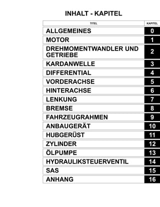
- 1. INHALT - KAPITEL TITEL KAPITEL ALLGEMEINES MOTOR DREHMOMENTWANDLER UND GETRIEBE KARDANWELLE DIFFERENTIAL VORDERACHSE HINTERACHSE LENKUNG BREMSE FAHRZEUGRAHMEN ANBAUGERÄT HUBGERÜST ZYLINDER ÖLPUMPE HYDRAULIKSTEUERVENTIL SAS ANHANG 0 1 2 3 4 5 6 7 8 9 10 11 12 13 14 15 16
- 2. 1-1 1 MOTOR Seite QUERSCHNITT-ANSICHT DES MOTORS.............................. 1-2 TECHNISCHE DATEN ...................... 1-4 LEISTUNGSKURVEN ....................... 1-5 MOTOR............................................. 1-8 AUSBAU·EINBAU .................................. 1-8 ENTLÜFTENDESKRAFTSTOFFSYSTEMS (STAPLERM/DIESELMOTOR) ...... 1-11 PRÜFUNG UND EINSTELLUNG DER MOTORDREHZAHL ............ 1-11 MOTOR 4Y ............................................. 1-11 MOTOR 1DZ-II.....2Z .................................. 1-15 LUFTFILTER ..................................... 1-16 TECHNISCHE DATEN........................... 1-16 BAUTEILE .............................................. 1-16 REINIGEN·PRÜFEN DES LUFTFILTERS ................................... 1-17 PRÜFUNGDES VERSTOPFUNGSANZEIGESYSTEMS....... 1-18 KÜHLER ........................................... 1-18 BAUTEILE .............................................. 1-18 TECHNISCHE DATEN........................... 1-19 TABELLE DER KÜHLMITTEL-FÜLL- MENGE UND DER FROSTSCHUTZ- MITTELKONZENTRATION................. 1-19 SCHALLDÄMPFER UND AUSPUFFROHR .......................... 1-20 BAUTEILE .............................................. 1-20 AUSBAU•••••EINBAU .................................. 1-21 WARTUNG DES SCHALLDÄMPFERS MIT KATALYSATOR ........................... 1-21 BATTERIE........................................ 1-22 BAUTEILE .............................................. 1-22 TECHNISCHE DATEN ............................ 1-22 INSPEKTION .......................................... 1-23 Seite PRÜFUNG•••••EINSTELLUNG DER KEILRIEMEN-SPANNUN ............... 1-24 FAHRPEDAL..................................... 1-25 BAUTEILE .............................................. 1-25 PRÜFUNG•••••EINSTELLUNG .................. 1-26 FAHRPEDAL-SCHALTER PRÜFUNG UND EINSTELLUNG .......................... 1-26 FAHRGESCHWINDIGKEITS- REGLER (OPT) ............................ 1-28 BAUTEILE .............................................. 1-28 ANSCHLUSS-SCHEMA ......................... 1-29 SCHALTPLAN ........................................ 1-30 DIAGNOSE ............................................. 1-31 AUSBAU•••••EINBAU .................................. 1-33 EINSTELLUNG VON GAS- UND DROSSELSEILZUG ........................... 1-36 FEHLERSUCHE ..................................... 1-37 DPF-II-SYSTEM (OPT) .................... 1-48 BAUTEILE .............................................. 1-48 ANSCHLUSS-SCHEMA ......................... 1-49 SCHALTPLAN ........................................ 1-50 DPF-SCHALLDÄMPFER AUSBAU•••••EINBAU .............................. 1-51 DPF-SCHALLDÄMPFER DEMONTAGE•••••PRÜFUNG· MONTAGE .......................................... 1-52 STEUERGERÄT AUSBAU·EINBAU ...... 1-54 GEBLÄSE AUSBAU•••••EINBAU ................ 1-55 PRÜFUNG DER EINZELNEN FUNKTIONSTEILE ............................. 1-56 LÖSCHVERFAHREN FÜR DIE FEHLER- CODES DES STEUERGERÄTS ......... 1-60 LÖSCHVERFAHREN FÜR DEN SPEICHER DES DPF-FILTERS ......... 1-60 REGENERIERUNGS-VERFAHREN ....... 1-60 FEHLERSUCHE ..................................... 1-61
- 3. 1-2 QUERSCHNITT-ANSICHT DES MOTORS Motor 4Y Motor 1DZ-II
- 5. 1-4 TECHNISCHE DATEN Otto-Motor 4Y (1.2-Tonner) 4-Takt-Otto-Motor 4-Zylinder-Reihenmotor, längs eingebaut Keilförmig Oben hängende Ventile, Ketten getrieben 91,0 ×86,0 2237 8,8 Ottokraftstoff :40 (54)/2400 Ottokraftstoff/Flüssiggas :35 (48)/2400 Flüssiggas :37 (50)/2400 Ottokraftstoff :162 (16,5)/1800 Ottokraftstoff/Flüssiggas :147 (15,0)/1600 Flüssiggas :157 (16,0)/1800 Ottokraftstoff :272 (200)/2300 Ottokraftstoff/Flüssiggas :258 (190)/2400 Flüssiggas :252 (185)/2400 134 2600 Motor Gegenstand Motor-Typ Anzahl und Anordnung der Zylinder Verbrennungsraum-Typ Ventiltrieb Bohrung x Hub mm Gesamthubraum cm3 Verdichtungsverhältnis Maximale Leistung kW (PS) min-1 Maximales Drehmoment Nm (kpm) min-1 Mindest-Kraftstoff verbrauch g/kW-h (g/PS-h)bei min-1 Betriebsmasse kg Geregelte Maximaldrehzahl ohne Last min-1 4Y (3.J3,5-Tonner) ← ← ← ← ← ← ← Ottokraftstoff :43 (58)/2600 Ottokraftstoff/Flüssiggas :38 (52)/2600 Flüssiggas :40 (54)/2600 ← ← ← 2800 Diesel-Motoren 1DZ-II (2.3-Tonner) ← ← ← ← ← ← ← 44 (60)/2600 ← ← ← 2800 Motor Gegenstand Motor-Typ Anzahl und Anordnung der Zylinder Verbrennungsraum-Typ Ventiltrieb Bohrung x Hub mm Gesamthubraum cm3 Verdichtungsverhältnis Maximale Leistung kW (PS) min-1 Maximales Drehmoment Nm (kpm) min-1 Mindestkrafstoff-Verbrauch g/kW-h (g/PS-h) min-1 Betriebsmasse kg Geregelte Maximaldrehzahl ohne Last min-1 1DZ-II (1-Tonner) 4-Takt-Diesel-Motor 4-Zylinder-Reihenmotor, längs eingebaut Mit Wirbelkammer Oben hängende Ventile, Zahnrad getrieben 86,0 × 107,0 2486 21,5 40 (55)/2400 167 (17,0)/1600 252 (185)/1400 162 2600 2Z ← ← Mit Direkteinspritzung ← 98,0 × 115,0 3469 18,6 49 (66)/2200 216 (22,0)/1600 209 (154)/1600 212 2400 Hinweis: Bei den 2•••••3-Tonnern mit 1DZ-II-Diesel-Motor, die mit einem Fahrgeschwindigkeits-Regelsystem (OPT) ausgerüstet sind, sind die Leistungsdaten und Leistungskurven dieselben wie die der 1- Tonner mit 1DZ-II-Motor.
- 6. 1-5 1 LEISTUNGSKURVEN Motor 4Y (1•••••2-Tonner) 147Nm (15,0kpm)/1600min-1 162Nm (16,5kpm)/1800min-1 157Nm (16,0kpm)/1800min-1 18 16 14 12 10 180 160 140 120 100 kpm Nm 40kW (54PS)/2400min-1 37kW (50PS)/2400min-1 35kW (48PS)/2400min-1 258g/kW•h (190g/PS•h)/2400min-1 252g/kW•h (185g/PS•h)/2400min-1 272g/kW•h (200g/PS•h)/2300min-1 260 240 220 200 180 320 300 280 260 240 340 360 g/PS•h g/kW•h 6 10 14 18 22 26 X102 kW 60 50 40 30 50 40 30 20 10 20 10 PS Ottokraftstoff Flüssiggas Ottokraftstoff/Flüssiggas Motorleistung MotordrehmomentMotordrehzahl min-1 Kraftstoffverbrauch 4Y Engine (3••••• J3,5 ton Series) kW 60 50 40 30 50 40 30 20 10 20 10 PS 18 16 14 12 10 180 160 140 120 100 kpm Nm 162Nm (16,5kpm)/1800min-1 157Nm (16,0kpm)/1800min-1 147Nm (15,0kpm)/1600min-1 43kW (58PS)/2600min-1 40kW (54PS)/2600min-1 38kW (52PS)/2600min-1 258g/kW•h (190g/PS•h)/2400min-1 252g/kW•h (185g/PS•h)/2400min-1 272g/kW•h (200g/PS•h)/2300min-1 260 240 220 200 180 320 300 280 260 240 340 360 g/PS•h g/kW•h 6 10 14 18 22 26 30 X102 Ottokraftstoff Flüssiggas Ottokraftstoff/Flüssiggas Motordrehmoment Motorleistung Motordrehzahl min-1 Kraftstoffverbrauch
- 7. 1-6 Motor 1DZ-II (1-Tonner) kpm Nm 17 16 15 14 13 165 155 145 135 125 167Nm (17,0kpm)/1600min-1 40kW (55PS)/2400min-1 kW 60 50 40 30 50 40 30 20 10 20 PS 252g/kW•h (185g/PS•h)/1400min-1 200 190 180 250 240 260 270 g/PS•h g/kW•h 6 14 18 22 26 X102 Kraftstoffverbrauch Motordrehzahl min-1 Motorleistung Motordrehmoment Motor 1DZ-II (2.3-Tonner) kpm Nm 17 16 15 14 13 165 155 145 135 125 167Nm (17,0kpm)/1600min-1 44kW (60PS)/2600min-1 kW 60 50 40 30 50 40 30 20 10 20 PS 252g/kW•h (185g/PS•h)/1400min-1 210 200 190 250 240 260 270 g/PS•h g/kW•h 180 10 14 18 22 26 30 X102 Kraftstoffverbrauch Motordrehzahl min-1 Motorleistung Motordrehmoment
- 8. 1-7 1 Motor 2Z kpm Nm 23 22 21 20 19 225 215 205 195 185 216Nm (22,0kpm)/1600min-1 49kW (66PS)/2200min-1 kW 70 60 50 40 50 40 30 20 30 PS 209g/kW•h (154g/PS•h)/1600min-1 160 150 140 200 190 210 220 g/PS•h g/kW•h 10 14 18 22 26 X102 MotordrehmomentKraftstoffverbrauch Motordrehzahl min-1 Motorleistung
- 9. 1-8 AUSBAU•••••EINBAU T = Nm (kpcm) Motorlager-Mutter Endscheiben-Befestigungsschraube Antriebsscheiben-Befestigungsschraube (zur Verbindung von Motor und Kurbelwelle) Antriebsscheiben-Befestigungsschraube (zur Verbindung mit dem Drehmomentwandler) Befestigungsschraube für Drehmomentwandler-Gehäuse T = 53,9 ~ 99,0 (550 ~ 1010) T = 49,0 ~ 78,5 (500 ~ 800) 4Y: T = 56,9 ~ 64,7 (580 ~ 660) 1DZ-II•2Z: T = 76,5 ~ 93,2 (780 ~ 950) T = 14,7 ~ 21,6 (150 ~ 220) T = 29,4 ~ 44,1 (300 ~ 450) MOTOR
- 10. 1-9 Ausbauverfahren 1 Motorhaube ausbauen (siehe Seite 9-5.) 2 Bodenblech ausbauen. 3 Kühlmittel ablassen. 4 Batterie und Batteriehalter ausbauen. 5 Relaiskasten ausbauen und die Befestigungsschrauben der Grundplatten von elektrischen Teilen entfernen, um sie zu lösen. 6 Gasseilzug und Kraftstoffschlauch abtrennen. [Punkt 1] 7 Dieselfahrzeuge: Befestigungsschraube für Abscheiderhalterung entfernen, um ihn von der Halterung zu lösen. 8 Steckverbinder und Kabelsatz-Klemmen im Bereich des Motors abtrennen. 9 Kühlerschlauch des Drehmomentwandlers abtrennen. [Punkt 2] 10 Kühler ausbauen. 11 Luftfilterschlauch abtrennen. 12 Befestigungsschraube der Ölpumpe entfernen, um die Pumpe zu lösen. 13 Auspuffrohr abtrennen. 14 Kabel vom Anlassermotor abtrennen. 15 Unterseitenabdeckung entfernen. 16 Abdeckplatte entfernen. 17 Die sechs Befestigungsschrauben der Antriebsscheibe entfernen. 18 Motorlager-Muttern entfernen. 19 Den Motor leicht mit einem Flaschenzug anheben. [Punkt 3] 20 Das Drehmomentwandlergehäuse mit Holzblöcken abstützen. 21 Drehmomentwandlergehäuse und Motor voneinander trennen. [Punkt 4] 22 Den Motor mit Antriebsscheibe und Drehmomentwandler-Endscheibe entfernen. 23 Antriebsscheibe entfernen. 24 Drehmomentwandler-Endscheibe entfernen. 25 Anlassermotor entfernen. Einbauverfahren Der Einbau erfolgt in sinngemäß umgekehrter Reihenfolge des Ausbauverfahrens. Hinweis: ••••• Flüssiges Dichtmittel (08833-00080) vor dem Anziehen der Antriebsscheiben- Befestigungsschraube (zum Anschluss der Motor-Kurbelwelle) auftragen. ••••• Nach dem Einbau des Motors das Kraftstoffsystem entlüften. (Für Diesel-Fahrzeuge) (siehe Seite 1-11.)
- 11. 1-10 Punktarbeitsgänge [Punkt 1] Ausbau: Ausrichtmarkierungen auf dem Kraftstoffschlauch und dem Anschlussflansch anbringen. [Punkt 2] Ausbau: Eine Ausrichtmarkierung auf dem Kühlerschlauch und dem Drehmomentwandler-Kühlerschlauch anbringen. [Punkt 3] Ausbau•••••Einbau: SST 09010-20111-71 --- 09010-23320-71 --- Ausbau: Den Motor provisorisch mit einem Flaschenzug anheben, bis die Motorlagerschraube vollständig aus der Bohrung im Rahmen frei kommt. SST SST [Punkt 4] Ausbau: Zum Trennen einen Flachklingen-Schraubendreher verwenden. Wenn die Teile zu fest sitzen, die Haken-Posi- tion des SST verändern, um den Motorwinkel zur Erleichterung des Trennvorgangs zu verändern.
- 12. 1-11 ENTLÜFTEN DES KRAFTSTOFFSYSTEMS (STAPLER M/ DIESELMOTOR) 1. Die Handpumpe am Kraftstoffilter betätigen, bis die Pumpenbetätigung schwergängig wird. PRÜFUNG UND EINSTELLUNG DER MOTORDREHZAHL Hinweis: Den Motor warmlaufen lassen und die folgenden Betriebsbedingungen des Staplers herstellen und Prüfung und Einstellung vornehmen. Kühlmittel-Temperatur: 80°°°°°C oder mehr, Motoröltemperatur: 70°°°°°C oder mehr, Betriebsflüssigkeits- Temperatur: 50°°°°°C oder mehr, Startautomatik ausgerastet (Motor 4Y) MOTOR 4Y Leerlaufdrehzahl und Leerlaufanhebung prüfen und einstellen <Stapler mit Otto-Motor> 1. Einen Drehzahlmesser anschließen. 2. Das Stellglied der Leerlaufanhebung aushängen und die Leerlaufanhebungs-Drehzahl prüfen. Standard: 1000 ± 30 min-1 3. Wenn der Messwert nicht im vorgeschriebenen Bereich liegt, die Einstellung mit der Einstellschraube B vornehmen. 4. Das Stellglied für die Leerlaufanhebung wieder anschließen. 5. Leerlaufdrehzahl prüfen. Standard: 750 min-1 6. Wenn der Messwert nicht im vorgeschriebenen Bereich liegt, die Einstellung mit der Einstellschraube A vornehmen. 7. Wenn die Drehzahl nach der Einstellung 3 oben immer noch zu hoch ist, das folgende Verfahren verwenden: A B Stellglied- Schlauch + 50 -0
- 13. 1-12 (1) Wenn die Stufenscheibe der Startautomatik das Stellglied berührt, obwohl die Kühlmitteltemperatur dem oben angegebenen Wert entspricht, die Startautomatik austauschen. (2) Wenn die Betätigerstange des Leerlaufanhebungs- Stellglieds und die Einstellschraube B miteinander in Berührung stehen, die Einstellschraube B entgegen dem Uhrzeigersinn drehen. <Flüssiggas/Otto-Motor oder Flüssiggas> 1. Einen Drehzahlmesser anschließen. 2. Das Stellglied der Leerlaufanhebung aushängen und die Leerlaufanhebungs-Drehzahl prüfen. Standard: Flüssiggas/Otto-Motor: 1000 ± 30 min-1 Stellglied- Schlauch B B B Stellglied- Schlauch Flüssiggas/Otto-Motor Stellglied- Schlauch LPG Flüssiggas: 1400 ± 30 min-1 Flüssiggas (Spezifikation für Frankreich): 1400 ± 30 min-1 3. Wenn der Messwert nicht im vorgeschriebenen Bereich liegt, die Einstellung mit der Einstellschraube B vornehmen. Bei Staplern mit Flüssiggas- Motor (Spezifikation für Frankreich) die Sicherungsmutter lösen, ehe die Einstellung vorgenommen wird. 4. Das Stellglied für die Leerlaufanhebung wieder anschließen. Sicherungsmuttern B 5. Leerlaufdrehzahl prüfen. Standard: Flüssiggas/Otto-Motor: 750 min-1 Flüssiggas: 800 min-1 Flüssiggas (Spezifikation für Frankreich) : 750 min-1 + 50 - 0 + 50 - 0 + 50 - 0 Flüssiggas (Spezifikation für Frankreich)
- 14. 1-13 A Regler Flüssiggas- Vergaser B C 6. Wenn die gemessenen Werte nicht im vorgeschriebenen Bereich liegen, die Einstellung entsprechend dem folgenden Verfahren durchführen: (1) Die Einstellung durch Drehen der Einstellschraube B (Stapler mit Flüssiggas-Motor) oder C (Stapler mit Flüssiggas/Otto-Motor) vornehmen. (Wenn die Drehzahl unter dem vorgeschriebenen Wert liegt, die Einstellschraube A vorher entgegen dem Uhrzeigersinn drehen.) (2) Die Einstellschraube A langsam im Uhrrzeigersinn oder entgegen dem Uhrzeigersinn drehen, bis die Höchstdrehzahl erreicht wird. (3) Die Positionen der Einstellschrauben B und C dadurch bestimmen, dass die Schritte (1) und (2) wiederholt werden, bis der in Schritt (2) erzielte Wert der Vorschrift entspricht. (4) Die Einstellschraube A langsam im Uhrzeigersinn drehen, bis die CO-Konzentration 2 bis 3% erreicht und dann von der Position aus, wo die Drehzahl abzufallen beginnt, um 45 Grad entgegen dem Uhrzeigersinn drehen. E D Flüssiggas (Spezifikation für Frankreich) (1) Die Einstellung durch Drehen der Einstellschraube D (Stapler mit Flüssiggas-Motor) vornehmen. (Wenn die Drehzahl unter dem vorgeschriebenen Wert liegt, die Einstellschraube E vorher entgegen dem Uhrzeigersinn drehen.) (2) Die Positionen der Einstellschraube D dadurch bestimmen, dass der Schritt (1) wiederholt wird, bis der in Schritt (1) erzielte Wert der Vorschrift entspricht. (3) Die Einstellschraube E langsam entgegen dem Uhrzeigersinn drehen, bis die CO-Konzentration 2 bis 3% erreicht und dann von der Position aus, wo die Drehzahl abzufallen beginnt, um 45 Grad entgegen dem Uhrzeigersinn drehen. Prüfung•••••Einstellung der Höchstdrehzahl ohne Last <Stapler mit Otto-Motor, Flüssiggas oder Flüssiggas/Otto- Motor> 1. Einen Drehzahlmesser anbringen. 2. Die Höchstdrehzahl ohne Last prüfen und einstellen. (1) Vollgas geben und die Höchstdrehzahl ohne Last messen. Standard: Motor 4Y: 1•2-Tonner: .....................2600 ± 50 min-1 3•J3,5-Tonner: ..............2800 ± 50 min-1 (2) Wenn der Wert nicht im vorgeschriebenen Bereich liegt, folgende Einstellungen vornehmen: Die Versiegelung entfernen und die Sicherungs- schraube lösen. Das Fahrpedal ganz niederdrücken. Die Einstellschraube des Luftreglers mit einem Flachklingenschraubendreher konstant halten und die Buchse zur Einstellung drehen. Sicherungsschrauben Festhalten Einstellschraube Buchse
- 15. 1-14 3. Drehzahlabfall bei Erreichen des Höchsdrucks prüfen und einstellen. (1) Den Motor mit Maximaldrehzahl betreiben und den Neigungshebel ganz nach hinten ziehen, dann den Drehzahlabfall (Drehzahlabfall bei Höchstdruck) messen, wenn der Höchstdruck erreicht wird. Standard: Innerhalb 300 min-1 Neigungshebel (2) Wenn der gemessene Wert nicht im vorgeschriebenen Bereich liegt, die Einstellung entsprechend dem folgenden Verfahren durchführen: Die Einstellschraube entgegen dem Uhrzeigersinn drehen, um den Drehzahlabfall bei Erreichen des Höchstdrucks zu verminden. Die Schraube um 1/10 einer Umdrehung zurückstellen, um eine Verdrehspannung der Feder im Luftregler zu beseitigen. Die Höchstdrehzahl ohne Last einstellen. Die Schritte , und wiederholen, bis der gemessene Wert im vorgeschriebenen Bereich liegt. 4. Unkontrollierten Drehzahlanstieg prüfen und einstellen. (1) Prüfen, ob die Drehzahl bei Erreichen des Neigungs- Höchstdrucks bei Höchstdrehzahl ohne Last unkontrolliert ansteigt. (2) Wenn ein unkontrollierter Leerlaufanstieg einmal oder häufiger auftritt, die Einstellung entsprechend dem folgenden Verfahren vornehmen: Die Einstellschraube um 1/2 Umdrehung oder mehr im Uhrzeigersinn drehen. Die Schraube um 1/4 Umdrehung entgegen dem Uhrzeigersinn zurückstellen. Abschließend die Schraube um 1/10 einer Umdrehung zurückstellen, um eine Verdrehspannung der Feder im Luftregler zu beseitigen. Die Höchstdrehzahl ohne Last einstellen. Die Schritte bis wiederholen, bis kein unkontrollierter Drehzahlanstieg mehr erfolgt. 5. Die in den Schritten 2 bis 4 beschriebenen Einstell- vorgänge wiederholen, bis die vorgeschriebenen Werte erreicht sind. 6. Die Sicherungsschraube wieder versiegeln.
- 16. 1-15 MOTOR 1DZ-II•••••2Z Prüfung•••••Einstellung der Leerlaufdrehzahl 1. Einen Drehzahlmesser am Motor anbringen. 2. Die Leerlaufdrehzahl prüfen. Standard: 750 ± 25 min-1 3. Wenn der gemessene Wert nicht im vorgeschriebenen Bereich liegt, die Sicherungsmutter lösen und die Einstellung mit der Einstellschraube A vornehmen. Prüfung•••••Einstellung der Höchstdrehzahl ohne Last 1. Einen Drehzahlmesser anbringen. 2. Die Höchstdrehzahl ohne Last prüfen und einstellen. (1) Vollgas geben und die Höchstdrehzahl ohne Last messen. Standard: Motor 1DZ-II: 1-Tonner: .................................... 2600 ± 50 min-1 Spezifikation mit Fahrgeschwindigkeits- Regler: ........................................ 2600 ± 50 min-1 2•••••3-Tonner: ................................ 2800 ± 50 min-1 Motor 2Z: ........................................ 2400 ± 50 min-1 (2) Wenn der Wert nicht im vorgeschriebenen Bereich liegt, folgende Einstellungen vornehmen: Die Versiegelung entfernen und die Sicherungs- schraube lösen. Die Einstellung mit der Einstellschraube B vornehmen. 3. Drehzahlabfall bei Erreichen des Höchsdrucks prüfen und einstellen. (1) Den Motor mit Maximaldrehzahl betreiben und den Neigungshebel ganz nach hinten ziehen, dann den Drehzahlabfall (Drehzahlabfall bei Höchstdruck) messen, wenn der Höchstdruck erreicht wird. Standard: Innerhalb 200 min-1 4. Die Einstellschrauben nach Abschluss der Einstell- arbeiten wieder versiegeln. A B Neigungshebel
- 17. 1-16 LUFTFILTER TECHNISCHE DATEN Typ Größe Lufteinlasssystem Wirksame Filterfläche cm2 Sonstiges Einfachfilter (STD) Wirbelstromfilter 7 Zoll Frischlufteinlass 14600 Mit Evakuierungsventil Doppelfilter (OPT) ← ← ← Aussen: 18600 Innen: 510 ← BAUTEILE 1703
- 18. 1-17 REINIGEN·PRÜFEN DES LUFTFILTERS 1. Motorhaube öffnen. 2. Filterelement ausbauen. Hinweis: Beim Doppelfilter (OPT) das innere Element zu keinem anderen Zweck als zum Auswechseln entfernen. 3. Reinigen des Filterelements (1) Normalerweise genügt zur Reinigung das Ausblasen mit Pressluft (7 kp/cm2 oder weniger) von innen nach außen entlang der Falten des Elements. Bei starker Verschmutzung kann das Filterelement ausge- waschen werden. (2) Waschvorgang für das Filterelement Neutrales Reinigungsmittel in lauwarmem Wasser (ca. 40°C) auflösen und das Filterelement etwa 30 Minuten lang in der Waschlösung untertauchen. Danach sorgfältig mit klarem Wasser spülen. [Wasserdruck: 275kPa (2,8 kp/cm2 oder weniger] Nachdem Waschen das Element an der Luft oder mit einem Fön (kalte Luft) trochen. Hinweis: ••••• Während des Waschens ist daraufzuachten, dass das Element nicht beschädigt wird. ••••• Niemals Druckluft oder Heißluft zum Trocknen verwenden. 4. Evakuierungsventil (Staubablaßventil) reinigen. (1) Die Spitze des Evakuierungsventils festhalten und Staub und Schmutz aus dem Inneren des Ventils ablassen. 5. Prüfen des Filterelements. (1) Nachdem das Filterelement gereinigt wurde, kann das Element durch Einführen einer Lampe auf Beschädigung geprüft werden. Werden kleine Löcher, Risse oder sonstige Beschädigungen festgestellt, ist das Filterelement durch ein neues zu ersetzen. 6. Austausch des Filterelements Das Filterelement ist nach sechs Waschvorgängen oder spätestens nach 12 Monaten auszutauschen. Stapler ohne Fahrgeschwindigkeits- Regler 7. Das Element einbauen (1) Das Element so einbauen, dass das Evaku- ierungsventil wie in der Abbildung gezeigt ausgerichtet ist. Stapler mit Fahrgeschwindigkeits- Regler 60° 25°
- 19. Thank you very much for your reading. Please Click Here. Then Get COMPLETE MANUAL. NO WAITING NOTE: If there is no response to click on the link above, please download the PDF document first and then click on it.
- 20. 1-18 PRÜFUNG DES VERSTOPFUNGSANZEIGESYSTEMS 1. Prüfen der Warnlampe (1) Prüfen, ob die Luftfilterwarnlampe aufleuchtet, wenn der Zündschalter auf ON steht und die Lampe erlischt, sobald der Motor anspringt. 2. Einzelprüfung (1) Durchgang prüfen, während mit einem “Mity vac”- Unterdruck auf den Unterdruckschalter ausgeübt wird. Standard Stapler mit Ottomotor: 2942 ± 294 Pa (300 ± 30 mm H2O) (22,1 ± 2,2 mmHg): Durchgang Stapler mit Dieselmotor: 7473 ± 569 Pa (762 ± 58 mm H2O) (56.0 ± 4.3 mmHg) : Durchgang KÜHLER BAUTEILE 1603
- 21. 1-19 Gesamtfüll- menge Kühlmittel 7,4 5,9 9,3 8,3 9,0 9,5 8,2 8,8 9,5 8,8 TECHNISCHE DATEN Typ Querstrom Lamellenform Wellenförmige Lamellen Kühlmittel-Füllmenge (im Kühler) Siehe nachfolgende Tabelle Kühlerdeckel-Öffnungsdruck kPa(kp/cm2 ) 88 ± 14.7 (0,9 ± 0,15) Sonstiges Eingebauter Drehmomentwandlerkühler (Stapler mit Drehmomentwandler) TABELLE DER KÜHLMITTEL-FÜLLMENGE UND DER FROSTSCHUTZMITTELKONZENTRATION Einheit: Füllmenge 2,5 2,5 3,7 3,7 3,7 3,7 3,7 3,7 3,7 3,7 Kühlmittel- konzentration 30% (bis -15°C) 2,2 1,8 2,8 2,5 2,7 2,9 2,5 2,6 2,9 2,6 Kühlmittel- konzentration 50% (bis -35°C) 3,7 3,0 4,7 4,2 4,5 4,8 4,1 4,4 4,8 4,4 Korrosions- schutzmittel 5% 0,4 0,3 0,5 0,4 0,5 0,5 0,4 0,4 0,5 0,4 4Y 1DZ-II 4Y 1DZ-II 2Z 4Y 1DZ-II 2Z 4Y 2Z 1-Tonner 2-Tonner 3-Tonner J3,5-Tonner Hinweis: ••••• Die Gesamtfüllmenge des Kühlmittels schließt die Füllmenge des Ausgleichsbehälters nicht mit ein. ••••• Füllmenge des Ausgleichsbehälters: 0,6 (bei Füllung bis zur FULL-Marke)