Thin Plates And Shells Theory Analysis And Applications 1st Theodor Krauthammer
Thin Plates And Shells Theory Analysis And Applications 1st Theodor Krauthammer
Thin Plates And Shells Theory Analysis And Applications 1st Theodor Krauthammer
Thin Plates And Shells Theory Analysis And Applications 1st Theodor Krauthammer
Thin Plates And Shells Theory Analysis And Applications 1st Theodor Krauthammer
1.
Thin Plates AndShells Theory Analysis And
Applications 1st Theodor Krauthammer download
https://ebookbell.com/product/thin-plates-and-shells-theory-
analysis-and-applications-1st-theodor-krauthammer-877392
Explore and download more ebooks at ebookbell.com
2.
Here are somerecommended products that we believe you will be
interested in. You can click the link to download.
Boundary Integral Equation Methods And Numerical Solutions Thin Plates
On An Elastic Foundation 1st Edition Christian Constanda
https://ebookbell.com/product/boundary-integral-equation-methods-and-
numerical-solutions-thin-plates-on-an-elastic-foundation-1st-edition-
christian-constanda-10313868
Homogenization Of Heterogeneous Thin And Thick Plates 1st Edition
Karam Sab
https://ebookbell.com/product/homogenization-of-heterogeneous-thin-
and-thick-plates-1st-edition-karam-sab-5435202
Thin Places Six Postures For Creating And Practicing Missional
Community 1st Edition Jon Huckins
https://ebookbell.com/product/thin-places-six-postures-for-creating-
and-practicing-missional-community-1st-edition-jon-huckins-51397192
Thin Places A Natural History Of Healing And Home Kerri N Dochartaigh
https://ebookbell.com/product/thin-places-a-natural-history-of-
healing-and-home-kerri-n-dochartaigh-46278050
3.
Thin Places EssaysFrom In Between Jordan Kisner
https://ebookbell.com/product/thin-places-essays-from-in-between-
jordan-kisner-44880628
Static And Dynamic Buckling Of Thinwalled Plate Structures 1st Edition
Tomasz Kubiak Auth
https://ebookbell.com/product/static-and-dynamic-buckling-of-
thinwalled-plate-structures-1st-edition-tomasz-kubiak-auth-4245544
The Peerage Of Scotland Containing An Historical And Genealogical
Account Of The Nobility Of That Kingdom Collected From The Public
Records And Ancient Chartularies Of This Nation Illustrated With
Copperplates By Robert Douglas Esq Robert Douglas
https://ebookbell.com/product/the-peerage-of-scotland-containing-an-
historical-and-genealogical-account-of-the-nobility-of-that-kingdom-
collected-from-the-public-records-and-ancient-chartularies-of-this-
nation-illustrated-with-copperplates-by-robert-douglas-esq-robert-
douglas-231331444
The Peerage Of Scotland Containing An Historical And Genealogical
Account Of The Nobility Of That Kingdom Collected From The Public
Records And Ancient Chartularies Of This Nation Illustrated With
Copperplates By Robert Douglas Esq Douglas
https://ebookbell.com/product/the-peerage-of-scotland-containing-an-
historical-and-genealogical-account-of-the-nobility-of-that-kingdom-
collected-from-the-public-records-and-ancient-chartularies-of-this-
nation-illustrated-with-copperplates-by-robert-douglas-esq-
douglas-231332638
More Than You Know Finding Financial Wisdom In Unconventional Places
Updated And Expanded Michael Mauboussin
https://ebookbell.com/product/more-than-you-know-finding-financial-
wisdom-in-unconventional-places-updated-and-expanded-michael-
mauboussin-51903366
10.
1
Introduction
1.1 GENERAL
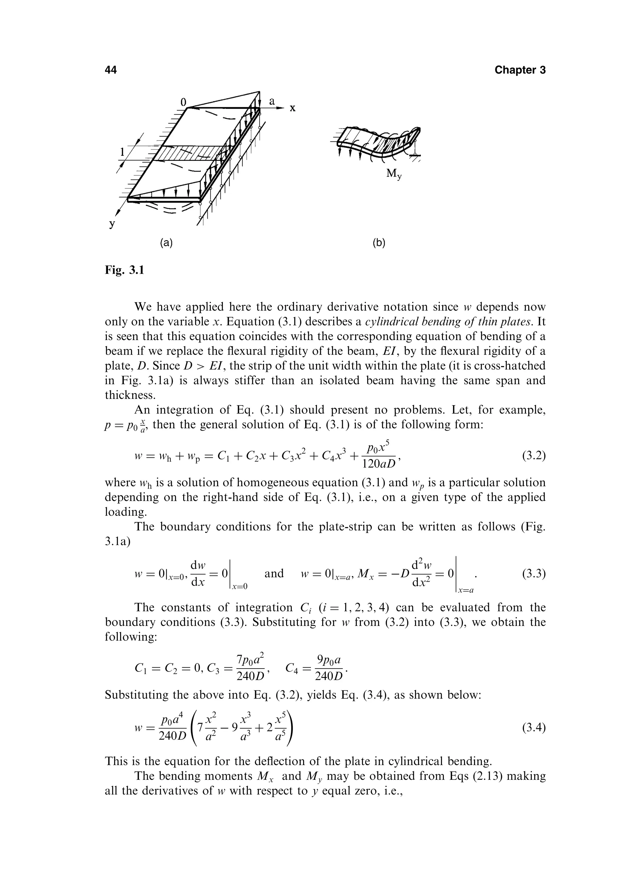
Thin platesare initially flat structural members bounded by two parallel planes,
called faces, and a cylindrical surface, called an edge or boundary. The generators
of the cylindrical surface are perpendicular to the plane faces. The distance between
the plane faces is called the thickness (h) of the plate. It will be assumed that the plate
thickness is small compared with other characteristic dimensions of the faces (length,
width, diameter, etc.). Geometrically, plates are bounded either by straight or curved
boundaries (Fig. 1.1). The static or dynamic loads carried by plates are predomi-
nantly perpendicular to the plate faces.
The load-carrying action of a plate is similar, to a certain extent, to that of
beams or cables; thus, plates can be approximated by a gridwork of an infinite
number of beams or by a network of an infinite number of cables, depending on
the flexural rigidity of the structures. This two-dimensional structural action of
plates results in lighter structures, and therefore offers numerous economic advan-
tages. The plate, being originally flat, develops shear forces, bending and twisting
moments to resist transverse loads. Because the loads are generally carried in both
directions and because the twisting rigidity in isotropic plates is quite significant, a
plate is considerably stiffer than a beam of comparable span and thickness. So, thin
plates combine light weight and a form efficiency with high load-carrying capacity,
economy, and technological effectiveness.
Because of the distinct advantages discussed above, thin plates are extensively
used in all fields of engineering. Plates are used in architectural structures, bridges,
hydraulic structures, pavements, containers, airplanes, missiles, ships, instruments,
machine parts, etc. (Fig. 1.2).
We consider a plate, for which it is common to divide the thickness h into equal
halves by a plane parallel to its faces. This plane is called the middle plane (or simply,
1
Part I
Thin Plates
the midplane) ofthe plate (Fig. 1.3). Being subjected to transverse loads, an initially
flat plate deforms and the midplane passes into some curvilinear surface, which is
referred to as the middle surface. With the exception of Secs 3.8 and 4.8, we will
consider only plates of constant thickness. For such plates, the shape of a plate is
adequately defined by describing the geometry of its middle plane. Depending on the
shape of this midplane, we will distinguish between rectangular, circular, elliptic, etc.,
plates.
A plate resists transverse loads by means of bending, exclusively. The flexural
properties of a plate depend greatly upon its thickness in comparison with other
dimensions. Plates may be classified into three groups according to the ratio a=h,
where a is a typical dimension of a plate in a plane and h is a plate thickness. These
groups are
1. The first group is presented by thick plates having ratios a=h 8 . . . 10. The
analysis of such bodies includes all the components of stresses, strains, and displace-
ments as for solid bodies using the general equations of three-dimensional elasticity.
2. The second group refers to plates with ratios a=h 80 . . . 100. These plates
are referred to as membranes and they are devoid of flexural rigidity. Membranes
carry the lateral loads by axial tensile forces N (and shear forces) acting in the plate
middle surface as shown in Fig. 1.7. These forces are called membrane forces; they
produce projection on a vertical axis and thus balance a lateral load applied to the
plate-membrane.
3. The most extensive group represents an intermediate type of plate, so-
called thin plate with 8 . . . 10 a=h 80 . . . 100. Depending on the value of the
ratio w=h, the ratio of the maximum deflection of the plate to its thickness, the
part of flexural and membrane forces here may be different. Therefore, this group,
in turn, may also be subdivided into two different classes.
a. Stiff plates. A plate can be classified as a stiff plate if w=h 0:2. Stiff plates
are flexurally rigid thin plates. They carry loads two dimensionally, mostly by inter-
nal bending and twisting moments and by transverse shear forces. The middle plane
deformations and the membrane forces are negligible. In engineering practice, the
term plate is understood to mean a stiff plate, unless otherwise specified. The concept
of stiff plates introduces serious simplifications that are discussed later. A funda-
Introduction 3
Fig. 1.3
13.
mental feature ofstiff plates is that the equations of static equilibrium for a plate
element may be set up for an original (undeformed) configuration of the plate.
b. Flexible plates. If the plate deflections are beyond a certain level,
w=h 0:3, then, the lateral deflections will be accompanied by stretching of the
middle surface. Such plates are referred to as flexible plates. These plates repre-
sent a combination of stiff plates and membranes and carry external loads by the
combined action of internal moments, shear forces, and membrane (axial) forces.
Such plates, because of their favorable weight-to-load ratio, are widely used by
the aerospace industry. When the magnitude of the maximum deflection is con-
siderably greater than the plate thickness, the membrane action predominates. So,
if w=h 5, the flexural stress can be neglected compared with the membrane
stress. Consequently, the load-carrying mechanism of such plates becomes of
the membrane type, i.e., the stress is uniformly distributed over the plate
thickness.
The above classification is, of course, conditional because the reference of the
plate to one or another group depends on the accuracy of analysis, type of loading,
boundary conditions, etc.
With the exception of Sec. 7.4, we consider only small deflections of thin plates,
a simplification consistent with the magnitude of deformation commonly found in
plate structures.
1.2 HISTORY OF PLATE THEORY DEVELOPMENT
The first impetus to a mathematical statement of plate problems, was probably done
by Euler, who in 1776 performed a free vibration analysis of plate problems [1].
Chladni, a German physicist, discovered the various modes of free vibrations
[2]. In experiments on horizontal plates, he used evenly distributed powder, which
formed regular patterns after induction of vibration. The powder accumulated along
the nodal lines, where no vertical displacements occurred. J. Bernoulli [3] attempted
to justify theoretically the results of these acoustic experiments. Bernoulli’s solution
was based on the previous work resulting in the Euler–D.Bernoulli’s bending beam
theory. J. Bernoulli presented a plate as a system of mutually perpendicular strips at
right angles to one another, each strip regarded as functioning as a beam. But the
governing differential equation, as distinct from current approaches, did not contain
the middle term.
4 Chapter 1
Fig. 1.4
14.
The French mathematicianGermain developed a plate differential equation
that lacked the warping term [4]; by the way, she was awarded a prize by the Parisian
Academy in 1816 for this work. Lagrange, being one of the reviewers of this work,
corrected Germain’s results (1813) by adding the missing term [5]; thus, he was the
first person to present the general plate equation properly.
Cauchy [6] and Poisson [7] were first to formulate the problem of plate bending
on the basis of general equations of theory of elasticity. Expanding all the character-
istic quantities into series in powers of distance from a middle surface, they retained
only terms of the first order of smallness. In such a way they obtained the governing
differential equation for deflections that coincides completely with the well-known
Germain–Lagrange equation. In 1829 Poisson expanded successfully the Germain–
Lagrange plate equation to the solution of a plate under static loading. In this
solution, however, the plate flexural rigidity D was set equal to a constant term.
Poisson also suggested setting up three boundary conditions for any point on a free
boundary. The boundary conditions derived by Poisson and a question about the
number and nature of these conditions had been the subject of much controversy
and were the subject of further investigations.
The first satisfactory theory of bending of plates is associated with Navier [8],
who considered the plate thickness in the general plate equation as a function of
rigidity D. He also introduced an ‘‘exact’’ method which transformed the differential
equation into algebraic expressions by use of Fourier trigonometric series.
In 1850 Kirchhoff published an important thesis on the theory of thin plates
[9]. In this thesis, Kirchhoff stated two independent basic assumptions that are now
widely accepted in the plate-bending theory and are known as ‘‘Kirchhoff’s hypoth-
eses.’’ Using these assumptions, Kirchhoff simplified the energy functional of 3D
elasticity theory for bent plates. By requiring that it be stationary he obtained the
Germain-Lagrange equation as the Euler equation. He also pointed out that there
exist only two boundary conditions on a plate edge. Kirchhoff’s other significant
contributions are the discovery of the frequency equation of plates and the intro-
duction of virtual displacement methods in the solution of plate problems.
Kirchhoff’s theory contributed to the physical clarity of the plate bending theory
and promoted its widespread use in practice.
Lord Kelvin (Thomson) and Tait [10] provided an additional insight relative to
the condition of boundary equations by converting twisting moments along the edge
of a plate into shearing forces. Thus, the edges are subject to only two forces: shear
and moment.
Kirchhoff’s book was translated by Clebsh [11]. That translation contains
numerous valuable comments by de Saint-Venant: the most important being the
extension of Kirchhoff’s differential equation of thin plates, which considered, in a
mathematically correct manner, the combined action of bending and stretching.
Saint-Venant also pointed out that the series proposed by Cauchy and Poissons as
a rule, are divergent.
The solution of rectangular plates, with two parallel simple supports and the
other two supports arbitrary, was successfully solved by Levy [12] in the late 19th
century.
At the end of the 19th and the beginning of the 20th centuries, shipbuilders
changed their construction methods by replacing wood with structural steel. This
change in structural materials was extremely fruitful in the development of various
Introduction 5
15.
plate theories. Russianscientists made a significant contribution to naval architec-
ture by being the first to replace the ancient trade traditions with solid mathematical
theories. In particular, Krylov [13] and his student Bubnov [14] contributed exten-
sively to the theory of thin plates with flexural and extensional rigidities. Bubnov laid
the groundwork for the theory of flexible plates and he was the first to introduce a
modern plate classification. Bubnov proposed a new method of integration of differ-
ential equations of elasticity and he composed tables of maximum deflections and
maximum bending moments for plates of various properties. Then, Galerkin devel-
oped this method and applied it to plate bending analysis. Galerkin collected numer-
ous bending problems for plates of arbitrary shape in a monograph [15].
Timoshenko made a significant contribution to the theory and application of
plate bending analysis. Among Timoshenko’s numerous important contributions are
solutions of circular plates considering large deflections and the formulation of
elastic stability problems [16,17]. Timoshenko and Woinowsky-Krieger published
a fundamental monograph [18] that represented a profound analysis of various
plate bending problems.
Extensive studies in the area of plate bending theory and its various applica-
tions were carried out by such outstanding scientists as Hencky [19], Huber [20], von
Karman [21,22], Nadai [23], Föppl [24].
Hencky [19] made a contribution to the theory of large deformations and the
general theory of elastic stability of thin plates. Nadai made extensive theoretical and
experimental investigations associated with a check of the accuracy of Kirchhoff’s
plate theory. He treated different types of singularities in plates due to a concen-
trated force application, point support effects, etc. The general equations for the
large deflections of very thin plates were simplified by Föppl who used the stress
function acting in the middle plane of the plate. The final form of the differential
equation of the large-deflection theory, however, was developed by von Karman. He
also investigated the postbuckling behavior of plates.
Huber, developed an approximate theory of orthotropic plates and solved
plates subjected to nonsymmetrical distributed loads and edge moments. The
bases of the general theory of anisotropic plates were developed by Gehring [25]
and Boussinesq [26]. Lekhnitskii [27] made an essential contribution to the develop-
ment of the theory and application of anisotropic linear and nonlinear plate analysis.
He also developed the method of complex variables as applied to the analysis of
anisotropic plates.
The development of the modern aircraft industry provided another strong
impetus toward more rigorous analytical investigations of plate problems. Plates
subjected to in-plane forces, postbuckling behavior, and vibration problems (flutter),
stiffened plates, etc., were analyzed by various scientists and engineers.
E. Reissner [28] developed a rigorous plate theory which considers the defor-
mations caused by the transverse shear forces. In the former Soviet Union the works
of Volmir [29] and Panov [30] were devoted mostly to solution of nonlinear plate
bending problems.
The governing equation for a thin rectangular plate subjected to direct com-
pressive forces Nx was first derived by Navier [8]. The buckling problem for a simply
supported plate subjected to the direct, constant compressive forces acting in one
and two directions was first solved by Bryan [31] using the energy method. Cox [32],
Hartmann [33], etc., presented solutions of various buckling problems for thin
6 Chapter 1
16.
rectangular plates incompression, while Dinnik [34], Nadai [35], Meissner [36], etc.,
completed the buckling problem for circular compressed plates. An effect of the
direct shear forces on the buckling of a rectangular simply supported plate was
first studied by Southwell and Skan [37]. The buckling behavior of a rectangular
plate under nonuniform direct compressive forces was studied by Timoshenko and
Gere [38] and Bubnov [14]. The postbuckling behavior of plates of various shapes
was analyzed by Karman et al. [39], Levy [40], Marguerre [41], etc. A comprehensive
analysis of linear and nonlinear buckling problems for thin plates of various shapes
under various types of loads, as well as a considerable presentation of available
results for critical forces and buckling modes, which can be used in engineering
design, were presented by Timoshenko and Gere [38], Gerard and Becker [42],
Volmir [43], Cox [44], etc.
A differential equation of motion of thin plates may be obtained by applying
either the D’Alambert principle or work formulation based on the conservation of
energy. The first exact solution of the free vibration problem for rectangular plates,
whose two opposite sides are simply supported, was achieved by Voight [45]. Ritz
[46] used the problem of free vibration of a rectangular plate with free edges to
demonstrate his famous method for extending the Rayleigh principle for obtaining
upper bounds on vibration frequencies. Poisson [7] analyzed the free vibration equa-
tion for circular plates. The monographs by Timoshenko and Young [47], Den
Hartog [48], Thompson [49], etc., contain a comprehensive analysis and design con-
siderations of free and forced vibrations of plates of various shapes. A reference
book by Leissa [50] presents a considerable set of available results for the frequencies
and mode shapes of free vibrations of plates could be provided for the design and for
a researcher in the field of plate vibrations.
The recent trend in the development of plate theories is characterized by a
heavy reliance on modern high-speed computers and the development of the most
complete computer-oriented numerical methods, as well as by introduction of more
rigorous theories with regard to various physical effects, types of loading, etc.
The above summary is a very brief survey of the historical background of the
plate bending theory and its application. The interested reader is referred to special
monographs [51,52] where this historical development of plates is presented in detail.
1.3 GENERAL BEHAVIOR OF PLATES
Consider a load-free plate, shown in Fig.1.3, in which the xy plane coincides with the
plate’s midplane and the z coordinate is perpendicular to it and is directed down-
wards. The fundamental assumptions of the linear, elastic, small-deflection theory of
bending for thin plates may be stated as follows:
1. The material of the plate is elastic, homogeneous, and isotropic.
2. The plate is initially flat.
3. The deflection (the normal component of the displacement vector) of the
midplane is small compared with the thickness of the plate. The slope of
the deflected surface is therefore very small and the square of the slope is
a negligible quantity in comparison with unity.
4. The straight lines, initially normal to the middle plane before bending,
remain straight and normal to the middle surface during the deformation,
Introduction 7
17.
and the lengthof such elements is not altered. This means that the vertical
shear strains xz and yz are negligible and the normal strain z may also
be omitted. This assumption is referred to as the ‘‘hypothesis of straight
normals.’’
5. The stress normal to the middle plane, z, is small compared with the
other stress components and may be neglected in the stress–strain rela-
tions.
6. Since the displacements of a plate are small, it is assumed that the middle
surface remains unstrained after bending.
Many of these assumptions, known as Kirchhoff’s hypotheses, are analogous to
those associated with the simple bending theory of beams. These assumptions result
in the reduction of a three-dimensional plate problem to a two-dimensional one.
Consequently, the governing plate equation can be derived in a concise and straight-
forward manner. The plate bending theory based on the above assumptions is
referred to as the classical or Kirchhoff’s plate theory. Unless otherwise stated, the
validity of the Kirchhoff plate theory is assumed throughout this book.
1.4 SURVEY OF ELASTICITY THEORY
The classical theories of plates and shells are an important application of the theory
of elasticity, which deals with relationships of forces, displacements, stresses, and
strains in an elastic body. When a solid body is subjected to external forces, it
deforms, producing internal strains and stresses. The deformation depends on the
geometrical configuration of the body, on applied loading, and on the mechanical
properties of its material. In the theory of elasticity we restrict our attention to linear
elastic materials; i.e., the relationships between stress and strain are linear, and the
deformations and stresses disappear when the external forces are removed. The
classical theory of elasticity assumes the material is homogeneous and isotropic,
i.e., its mechanical properties are the same in all directions and at all points.
The present section contains only a brief survey of the elasticity theory that will
be useful for the development of the plate theory. All equations and relations will be
given without derivation. The reader who desires to review details is urged to refer to
any book on elasticity theory – for example [53–55].
1.4.1 Stress at a point: stress tensor
Consider an elastic body of any general shape subjected to external loads which are
in equilibrium. Then, consider a material point anywhere in the interior of the body.
If we assign a Cartesian coordinate frame with axes x, y, and z, as shown in Fig. 1.5,
it is convenient to assign an infinitesimal element in the form of parallelepiped
(dx; dy; dz), with faces parallel to the coordinate planes. Stresses acting on the
faces of this element describe the intensity of the internal forces at a point on a
particular face. These stresses can be broken down into a normal component (normal
stress) and tangent component (shear stress) to the particular face. As a result, the
three stress components, denoted by xx; xy; xz; . . . ; will act on each face of the
element. The subscript notation for the stress components is interpreted as follows:
the first subscript indicates the direction of an outer normal to the face on which the
stress component acts; the second subscript relates to the direction of the stress itself.
8 Chapter 1
18.
Repeated subscripts willbe omitted in the future, i.e., the normal stresses will have
only one subscript indicating the stress direction. The following sign convention will
be adapted for the stress components: the positive sign for the normal stress will
correspond to a tensile stress, while the negative sign will correspond to a compres-
sive stress. The sign agreement for the shear stresses follows from the relationship
between the direction of an outer normal drawn to a particular face and the direction
of the shear stress component on the same face. If both the outer normal and the
shear stress are either in positive or negative directions relative to the coordinate
axes, then the shear stress is positive. If the outer normal points in a positive direc-
tion while the stress is in a negative direction (or vice versa), the shear stress is
negative. On this basis, all the stress components shown in Fig. 1.5 are positive.
On any one face these three stress components comprise a vector, called a surface
traction. The above-mentioned set of the stress components acting on the faces of the
element forms the stress tensor, TS, i.e.,
TS ¼
xxyxz
yxyyz
zxzyz
0
B
@
1
C
A; ð1:1Þ
which is symmetric with respect to the principal diagonal because of the reciprocity
law of shear stresses, i.e.,
xy ¼ yx; xz ¼ zx; yz ¼ zy: ð1:2Þ
Thus, only the six stress components out of nine in the stress tensor (1.1) are inde-
pendent. The stress tensor, TS, completely characterizes the three-dimensional state
of stress at a point of interest.
For elastic stress analysis of plates, the two-dimensional state of stress is of
special importance. In this case, z ¼ yz ¼ xz ¼ 0; thus, the two-dimensional stress
tensor has a form
TS ¼
xxy
yxy
; where xy ¼ yx ð1:3Þ
Introduction 9
Fig. 1.5
19.
1.4.2 Strains anddisplacements
Assume that the elastic body shown in Fig. 1.6 is supported in such a way that rigid
body displacements (translations and rotations) are prevented. Thus, this body
deforms under the action of external forces and each of its points has small elastic
displacements. For example, a point M had the coordinates x; y, and z in initial
undeformed state. After deformation, this point moved into position M 0
and its
coordinates became the following x0
¼ x þ u; y0
¼ y þ v, z0
¼ z0
þ w, where u, v,
and w are projections of the displacement vector of point M, vector MM0
, on the
coordinate axes x, y and z. In the general case, u, v, and w are functions of x, y, and
z.
Again, consider an infinitesimal element in the form of parallelepiped enclosing
point of interest M. Assuming that a deformation of this parallelepiped is small, we
can represent it in the form of the six simplest deformations shown in Fig. 1.7. The
first three deformations shown in Fig. 1.7a, b, and c define the elongation (or con-
traction) of edges of the parallelepiped in the direction of the coordinate axes and
can be defined as
x ¼
ðdxÞ
dx
; y ¼
ðdyÞ
dy
; z ¼
ðdzÞ
dz
; ð1:4Þ
and they are called the normal or linear strains. In Eqs (1.4), the increments dx can
be expressed by the second term in the Taylor series, i.e., dx ¼ ð@u=@xÞdx, etc.; thus,
we can write
x ¼
@u
@x
; y ¼
@v
@y
; z ¼
@w
@z
: ð1:5aÞ
The three other deformations shown in Fig. 1.7d, e, and f are referred to as shear
strains because they define a distortion of an initially right angle between the edges of
the parallelepiped. They are denoted by xy, xz, and yz. The subscripts indicate the
coordinate planes in which the shear strains occur. Let us determine, for example,
the shear strain in the xy coordinate plane. Consider the projection of the paralle-
lepiped, shown in Fig. 1.7d, on this coordinate plane. Figure 1.8 shows this projec-
10 Chapter 1
Fig. 1.6
20.
tion in theform of the rectangle before deformation (ABCD) and after deformation
(A0
B0
C0
D0
). The angle BAD in Fig. 1.8 deforms to the angle B0
A0
D0
, the deforma-
tion being the angle 0
þ 00
; thus, the shear strain is
xy ¼ 0
þ 00
ðaÞ
or it can be determined in terms of the in-plane displacements, u and v, as follows:
xy ¼
@v
@x dx
dx þ @u
@x dx
þ
@u
@y dy
dy þ @v
@y dy
¼
@v
@x
1 þ @u
@x
þ
@u
@y
1 þ @v
@y
:
Since we have confined ourselves to the case of very small deformations, we may
omit the quantities @u=@x and @v=@y in the denominator of the last expression, as
being negligibly small compared with unity. Finally, we obtain
Introduction 11
Fig. 1.7
Fig. 1.8
21.
xy ¼
@v
@x
þ
@u
@y
: ðbÞ
Similarly,we can obtain xz and yz. Thus, the shear strains are given by
xy ¼
@u
@y
þ
@v
@x
; xz ¼
@u
@z
þ
@w
@x
; yz ¼
@v
@z
þ
@w
@y
: ð1:5bÞ
Similar to the stress tensor (1.1) at a given point, we can define a strain tensor as
TD ¼
x
1
2
xy
1
2
xz
1
2
yx y
1
2
yz
1
2
zx
1
2
zy z
0
B
B
B
B
B
@
1
C
C
C
C
C
A
: ð1:6Þ
It is evident that the strain tensor is also symmetric because of
xy ¼ yx; xz ¼ zx; yz ¼ zy ð1:7Þ
1.4.3 Constitutive equations
The constitutive equations relate the stress components to strain components. For
the linear elastic range, these equations represent the generalized Hooke’s law. In the
case of a three-dimensional isotropic body, the constitutive equations are given by
[53].
x ¼
1
E
x y þ z
; y ¼
1
E
y x þ z
ð Þ
; z ¼
1
2
z y þ x
;
ð1:8aÞ
xy ¼
1
G
xy; xz ¼
1
G
xz; yz ¼
1
G
yz; ð1:8bÞ
where E, , and G are the modulus of elasticity, Poisson’s ratio, and the shear
modulus, respectively. The following relationship exists between E and G:
G ¼
E
2ð1 þ Þ
ð1:9Þ
1.4.4 Equilibrium equations
The stress components introduced previously must satisfy the following differential
equations of equilibrium:
@x
@x
þ
@xy
@y
þ
@xz
@z
þ Fx ¼ 0;
@y
@y
þ
@yx
@x
þ
@yz
@z
þ Fy ¼ 0;
@z
@z
þ
@zx
@x
þ
@zy
@y
þ Fz ¼ 0;
ð1:10Þ
12 Chapter 1
22.
where Fx; Fy;and Fz are the body forces (e.g., gravitational, magnetic forces). In
deriving these equations, the reciprocity of the shear stresses, Eqs (1.7), has been
used.
1.4.5 Compatibility equations
Since the three equations (1.10) for six unknowns are not sufficient to obtain a
solution, three-dimensional stress problems of elasticity are internally statically inde-
terminate. Additional equations are obtained to express the continuity of a body.
These additional equations are referred to as compatibility equations. In Eqs (1.5) we
have related the six strain components to the three displacement components.
Eliminating the displacement components by successive differentiation, the follow-
ing compatibility equations are obtained [53–55]:
@2
x
@y2
þ
@2
y
@x2
¼
@2
xy
@x@y
;
@2
y
@z2
þ
@2
z
@y2
¼
@2
yz
@y@z
; ð1:11aÞ
@2
z
@x2
þ
@2
x
@z2
¼
@2
xz
@x@z
;
@
@z
@yz
@x
þ
@xz
@y
@xy
@z
¼ 2
@2
z
@x@y
;
@
@x
@xz
@y
þ
@xy
@z
@yz
@x
¼ 2
@2
x
@y@z
; ð1:11bÞ
@
@y
@xy
@z
þ
@yz
@x
@xz
@y
¼ 2
@2
y
@x@z
:
For a two-dimensional state of stress (z ¼ 0, xz ¼ yz ¼ 0), the equilibrium condi-
tions (1.10) become
@x
@x
þ
@xy
@y
þ Fx ¼ 0;
@y
@y
þ
@yx
@x
þ Fy ¼ 0;
ð1:12Þ
and the compatibility equation is
@2
x
@y2
þ
@2
y
@x2
¼
@2
xy
@x@y
xz ¼ yz ¼ z ¼ 0
: ð1:13Þ
We can rewrite Eq. (1.13) in terms of the stress components as follows
@2
@x2
þ
@2
@y2
!
x þ y
¼ 0: ð1:14Þ
Introduction 13
23.
This equation iscalled Levy’s equation. By introducing Airy’s stress function x; y
ð Þ
which satisfies
x ¼
@2
@y2
; y ¼
@2
@x2
; xy ¼
@2
@x@y
; ð1:15Þ
Eq. (1.14) becomes
r2
r2
¼ 0; ð1:16Þ
where
r2
@2
@x2
þ
@2
@y2
ð1:17Þ
is the two-dimensional Laplace operator.
SUMMARY
For an elastic solid there are 15 independent variables: six stress components, six
strain components, and three displacements. In the case where compatibility is satis-
fied, there are 15 equations: three equilibrium equations, six constitutive relations,
and six strain-displacement equations.
REFERENCES
1. Euler, L., De motu vibratorio tympanorum, Novi Commentari Acad Petropolit, vol. 10,
pp. 243–260 (1766).
2. Chladni, E.F., Die Akustik, Leipzig, 1802.
3. Bernoulli, J., Jr., Essai theorique sur les vibrations de plaques elastiques rectangularies et
libers, Nova Acta Acad Petropolit, vol. 5, pp. 197–219 (1789).
4. Germain, S., Remarques sur la nature, les bornes et l’etendue de la question des surfaces
elastiques et equation general de ces surfaces, Paris, 1826.
5. Lagrange, J.L., Ann Chim, vol. 39, pp. 149–207 (1828).
6. Cauchy, A.L., Sur l’equilibre le mouvement d’une plaque solide, Exercises Math, vol. 3,
p. 328 (1828).
7. Poisson, S.D., Memoire sur l’equilibre et le mouvement des corps elastique, Mem Acad
Sci, vol. 8, p. 357 (1829).
8. Navier, C.L.M.H., Bulletin des Sciences de la Societe Philomathique de Paris, 1823.
9. Kirchhoff, G.R., Uber das gleichgewichi und die bewegung einer elastishem scheibe, J
Fuer die Reine und Angewandte Mathematik, vol. 40, pp. 51–88 (1850).
10. Lord Kelvin and Tait, P.G., Treatise on Natural Philosophy, vol. 1, Clarendon Press,
Oxford, 1883.
11. Clebsch, A. Theorie de l’Elasticite des Corps Solids, Avec des Notes Entendues de Saint-
Venant, Dunod, Paris, pp. 687–706 (1883).
12. Levy, M., Memoire sur la theorie des plaques elastiques planes, J Math Pure Appl, vol 3,
p. 219 (1899).
13. Krylov, A.N., On stresses experienced by a ship in a sea way, Trans Inst Naval Architects,
vol. 40, London, pp. 197–209, 1898.
14. Bubnov, I.G., Theory of Structures of Ships, vol. 2, St . Petersburg, 1914.
15. Galerkin, B.G., Thin Elastic Plates, Gostrojisdat, Leningrad, 1933 (in Russian).
16. Timoshenko, S.P., On large deflections of circular plates, Mem Inst Ways Commun, 89,
1915.
14 Chapter 1
24.
17. Timoshenko, S.P.,Sur la stabilite des systemes elastiques, Ann des Points et Chaussees,
vol. 13, pp. 496–566; vol. 16, pp. 73–132 (1913).
18. Timoshenko, S.P. and Woinowsky-Krieger, S., Theory of Plates and Shells, 2nd edn,
McGraw-Hill, New York, 1959.
19. Hencky, H., Der spanngszustand in rechteckigen platten (Diss.), Z Andew Math und
Mech, vol. 1 (1921).
20. Huber, M.T., Probleme der Static Techish Wichtiger Orthotroper Platten, Warsawa,
1929.
21. von Karman, T., Fesigkeitsprobleme in Maschinenbau, Encycl der Math Wiss, vol. 4, pp.
348–351 (1910).
22. von Karman,T., Ef Sechler and Donnel, L.H. The strength of thin plates in compression,
Trans ASME, vol. 54, pp. 53–57 (1932).
23. Nadai, A. Die formanderungen und die spannungen von rechteckigen elastischen platten,
Forsch a.d. Gebiete d Ingeineurwesens, Berlin, Nos. 170 and 171 (1915).
24. Foppl, A., Vorlesungen uber technische Mechanik, vols 1 and 2, 14th and 15th edns,
Verlag R., Oldenburg, Munich, 1944, 1951.
25. Gehring, F., Vorlesungen uber Mathematieche Physik, Mechanik, 2nd edn, Berlin,1877.
26. Boussinesq, J., Complements anne étude sur la theorie de l’equilibre et du mouvement
des solides elastiques, J de Math Pures et Appl , vol. 3, ses. t.5 (1879).
27. Leknitskii, S.G., Anisotropic Plates (English translation of the original Russian work),
Gordon and Breach, New York, 1968.
28. Reissner, E., The effect of transverse shear deformation on the bending of elastic plates, J
Appl Mech Trans ASME, vol. 12, pp. A69–A77 (1945).
29. Volmir, A.S., Flexible Plates and Shells, Gos. Izd-vo Techn.-Teoret. Lit-ry, Moscow,
1956 (in Russian).
30. Panov, D.Yu., On large deflections of circular plates, Prikl Matem Mech, vol. 5, No. 2,
pp. 45–56 (1941) (in Russian).
31. Bryan, G.N., On the stability of a plane plate under thrusts in its own plane, Proc London
Math Soc, 22, 54–67 (1981)
32. Cox, H.L, Buckling of Thin Plates in Compression, Rep. and Memor., No. 1553,1554,
(1933).
33. Hartmann, F., Knickung, Kippung, Beulung, Springer-Verlag, Berlin, 1933.
34. Dinnik, A.N., A stability of compressed circular plate, Izv Kiev Polyt In-ta, 1911 (in
Russian).
35. Nadai, A., Uber das ausbeulen von kreisfo
ormigen platten, Zeitschr VDJ, No. 9,10 (1915).
36. Meissner, E., Uber das knicken kreisfo
ormigen scheiben, Schweiz Bauzeitung, 101, pp. 87–
89 (1933).
37. Southwell, R.V. and Scan, S., On the stability under shearing forces of a flat elastic strip,
Proc Roy Soc, A105, 582 (1924).
38. Timoshenko, S.P. and Gere, J.M., Theory of Elastic Stability, 2nd edn, McGraw-Hill,
New York, 1961.
39. Karman, Th., Sechler, E.E. and Donnel, L.H., The strength of thin plates in compres-
sion, Trans ASME, 54, 53–57 (1952).
40. Levy, S., Bending of Rectangular Plates with Large Deflections, NACA, Rep. No.737,
1942.
41. Marguerre, K., Die mittragende briete des gedrückten plattenstreifens,
Luftfahrtforschung, 14, No. 3, 1937.
42. Gerard, G. and Becker, H., Handbook of Structural Stability, Part1 – Buckling of Flat
Plates, NACA TN 3781, 1957.
43. Volmir, A.S., Stability of Elastic Systems, Gos Izd-vo Fiz-Mat. Lit-ry, Moscow, 1963 (in
Russian).
44. Cox, H.l., The Buckling of Plates and Shells. Macmillan, New York, 1963.
Introduction 15
25.
45. Voight, W,Bemerkungen zu dem problem der transversalem schwingungen rechteckiger
platten, Nachr. Ges (Göttingen), No. 6, pp. 225–230 (1893).
46. Ritz, W., Theorie der transversalschwingungen, einer quadratischen platte mit frein
rändern, Ann Physic, Bd., 28, pp. 737–786 (1909).
47. Timoshenko, S.P. and Young, D.H., Vibration Problems in Engineering, John Wiley and
Sons., New York, 1963.
48. Den Hartog, J.P., Mechanical Vibrations, 4th edn, McGraw-Hill, New York, 1958.
49. Thompson, W.T., Theory of Vibrations and Applications, Prentice-Hill, Englewood Cliffs,
New Jersey, 1973.
50. Leissa, A.W., Vibration of Plates, National Aeronautics and Space Administration,
Washington, D.C., 1969.
51. Timoshenko, S.P., History of Strength of Materials, McGraw-Hill, New York, 1953.
52. Truesdell, C., Essays in the History of Mechanic., Springer-Verlag, Berlin, 1968.
53. Timoshenko, S.P. and Goodier, J.N., Theory of Elasticity, 3rd edn, McGraw-Hill, New
York, 1970.
54. Prescott, J.J., Applied Elasticity, Dover, New York, 1946.
55. Sokolnikoff, I.S., Mathematical Theory of Elasticity, 2nd edn, McGraw-Hill, New York,
1956.
16 Chapter 1
26.
2
The Fundamentals ofthe Small-
Deflection P late Bending Theory
2.1 INTRODUCTION
The foregoing assumptions introduced in Sec. 1.3 make it possible to derive the basic
equations of the classical or Kirchhoff’s bending theory for stiff plates. It is conve-
nient to solve plate bending problems in terms of displacements. In order to derive
the governing equation of the classical plate bending theory, we will invoke the three
sets of equations of elasticity discussed in Sec. 1.4.
2.2 STRAIN–CURVATURE RELATIONS (KINEMATIC EQUATIONS)
We will use common notations for displacement, stress, and strain components
adapted in elasticity (see Sec. 1.4). Let u; v; and w be components of the displacement
vector of points in the middle surface of the plate occurring in the x; y, and z
directions, respectively. The normal component of the displacement vector, w (called
the deflection), and the lateral distributed load p are positive in the downward
direction. As it follows from the assumption (4) of Sec. 1.3
z ¼ 0; yz ¼ 0; xz ¼ 0: ð2:1Þ
Integrating the expressions (1.5) for z; yz; and xz and taking into account Eq.
(2.1), we obtain
wz
¼ w x; y
ð Þ; uz
¼ z
@w
@x
þ u x; y
ð Þ; vz
¼ z
@w
@y
þ v x; y
ð Þ; ð2:2Þ
where uz
; vz
, and wz
are displacements of points at a distance z from the middle
surface. Based upon assumption (6) of Sec. 1.3, we conclude that u ¼ v ¼ 0. Thus,
Eqs (2.2) have the following form in the context of Kirchhoff’s theory:
17
27.
wz
¼ w x;y
ð Þ; uz
¼ z
@w
@x
; vz
¼ z
@w
@y
: ð2:3Þ
As it follows from the above, the displacements uz
and vz
of an arbitrary horizontal
layer vary linearly over a plate thickness while the deflection does not vary over the
thickness.
Figure 2.1 shows a section of the plate by a plane parallel to Oxz; y ¼ const:,
before and after deformation. Consider a segment AB in the positive z direction. We
focus on an arbitrary point B which initially lies at a distance z from the undeformed
middle plane (from the point A). During the deformation, point A displaces a dis-
tance w parallel to the original z direction to point A1. Since the transverse shear
deformations are neglected, the deformed position of point B must lie on the normal
to the deformed middle plane erected at point A1(assumption (4)). Its final position is
denoted by B1. Due to the assumptions (4) and (5), the distance z between the above-
mentioned points during deformation remains unchanged and is also equal to z.
We can also represent the displacement components uz
and vz
, Eqs (2.2), in the
form
uz
¼ z#x; vz
¼ z#y; ð2:4Þ
where
#x ¼
@w
@x
; #y ¼
@w
@y
ð2:5Þ
are the angles of rotation of the normal (normal I–I in Fig. 2.1) to the middle surface
in the Oxz and Oyz plane, respectively. Owing to the assumption (4) of Sec. 1.3, #x
and #y are also slopes of the tangents to the traces of the middle surface in the above-
mentioned planes.
Substitution of Eqs (2.3) into the first two Eqs (1.5a) and into the first Eq.
(1.5b), yields
z
x ¼ z
@2
w
@x2
; z
y ¼ z
@2
w
@y2
; z
xy ¼ 2z
@2
w
@x@y
; ð2:6Þ
18 Chapter 2
Fig. 2.1
28.
where the superscriptz refers to the in-plane strain components at a point of the
plate located at a distance z from the middle surface. Since the middle surface
deformations are neglected due to the assumption (6), from here on, this superscript
will be omitted for all the strain and stress components at points across the plate
thickness.
The second derivatives of the deflection on the right-hand side of Eqs. (2.6)
have a certain geometrical meaning. Let a section MNP represent some plane curve
in which the middle surface of the deflected plate is intersected by a plane y ¼ const.
(Fig. 2.2).
Due to the assumption 3 (Sec. 1.3), this curve is shallow and the square of the
slope angle may be regarded as negligible compared with unity, i.e., (@w=@xÞ2
1.
Then, the second derivative of the deflection, @2
w=@x2
will define approximately the
curvature of the section along the x axis, x. Similarly, @2
w=@y2
defines the curvature
of the middle surface y along the y axis. The curvatures x and y characterize the
phenomenon of bending of the middle surface in planes parallel to the Oxz and Oyz
coordinate planes, respectively. They are referred to as bending curvature and are
defined by
x ¼
1
x
¼
@2
w
@x2
; y ¼
1
y
¼
@2
w
@y2
ð2:7aÞ
We consider a bending curvature positive if it is convex downward, i.e., in the
positive direction of the z axis. The negative sign is taken in Eqs. (2.7a) since, for
example, for the deflection convex downward curve MNP (Fig. 2.2), the second
derivative, @2
w=@x2
is negative.
The curvature @2
w=@x2
can be also defined as the rate of change of the angle
#x ¼ @w=@x with respect to distance x along this curve. However, the above angle
can vary in the y direction also. It is seen from comparison of the curves MNP and
M1N1P1 (Fig. 2.2), separated by a distance dy. If the slope for the curve MNP
is @w=@x then for the curve M1N1P1 this angle becomes equal to
@w
@x
@
@y
@w
@x
dy
or
@w
@x
@2
w
@x@y
dy
!
. The rate of change of the angle @w=@x per
unit length will be ð@2
w=@x@y). The negative sign is taken here because it is assumed
Small-Deflection Plate Bending Theory 19
Fig. 2.2
29.
that when yincreases, the slope angle of the tangent to the curve decreases (by
analogy with the sign convention for the bending curvatures x and y). Similarly,
can be convinced that in the perpendicular section (for the variable x), the rate of
change of the angle @w=@y is characterized by the same mixed derivative
ð@2
w=@x@yÞ. By analogy with the torsion theory of rods, the derivative @2
w=@x@y
defines the warping of the middle surface at a point with coordinates x and y is called
the twisting curvature with respect to the x and y axes and is denotes by xy. Thus,
xy ¼ yx ¼
1
xy
¼
@2
w
@x@y
ð2:7bÞ
Taking into account Eqs (2.7) we can rewrite Eqs (2.6) as follows
x ¼ zx; y ¼ zy; xy ¼ 2zxy: ð2:8Þ
2.3 STRESSES, STRESS RESULTANTS, AND STRESS COUPLES
In the case of a three-dimensional state of stress, stress and strain are related by the
Eqs (1.8) of the generalized Hooke’s law. As was mentioned earlier, Kirchhoff’s
assumptions of Sec. 1.3 brought us to Eqs (2.1). From a mathematical standpoint,
this means that the three new equations (2.1) are added to the system of governing
equations of the theory of elasticity. So, the latter becomes overdetermined and,
therefore, it is necessary to also drop three equations. As a result, the three relations
out of six of Hookes’ law (see Eqs (1.8)) for strains (2.1) are discarded. Moreover, the
normal stress component z ¼ 0: Solving Eqs (1.8) for stress components x, y, and
xy, yields
x ¼
E
1 2
x þ y
; y ¼
E
1 2
y þ x
; xy ¼ Gxy: ð2:9Þ
The stress components are shown in Fig. 2.3a. The subscript notation and sign
convention for the stresses were given in Sec. 1.4.
20 Chapter 2
Fig. 2.3
30.
Introducing the platecurvatures, Eqs (2.7) and using Eqs (2.8), the above
equations appear as follows:
x ¼
Ez
1 2
ðx þ yÞ ¼
Ez
1 2
@2
w
@x2
þ
@2
w
@y2
!
;
y ¼
Ez
1
2 ðy þ xÞ ¼
Ez
1 2
@2
w
@y2
þ
@2
w
@x2
!
;
xy ¼
Ez
1 þ
xy ¼
Ez
1 þ
@2
w
@x@y
:
ð2:10Þ
It is seen from Eqs. (2.10) that Kirchhoff’s assumptions have led to a completely
defined law of variation of the stresses through the thickness of the plate. Therefore,
as in the theory of beams, it is convenient to introduce, instead of the stress compo-
nents at a point problem, the total statically equivalent forces and moments applied
to the middle surface, which are known as the stress resultants and stress couples. The
stress resultants and stress couples are referred to as the shear forces, Qx and Qy, as
well as the bending and twisting moments Mx; My, and Mxy, respectively. Thus,
Kirchhoff’s assumptions have reduced the three-dimensional plate straining problem
to the two-dimensional problem of straining the middle surface of the plate.
Referring to Fig. 2.3, we can express the bending and twisting moments, as well
as the shear forces, in terms of the stress components, i.e.,
Mx
My
Mxy
8
:
9
=
;
¼
ð
h=2
h=2
x
y
xy
8
:
9
=
;
zdz ð2:11Þ
and
Qx
Qy
( )
¼
ð
h=2
h=2
xz
yz
( )
dz: ð2:12Þ
Because of the reciprocity law of shear stresses (xy ¼ yx), the twisting moments on
perpendicular faces of an infinitesimal plate element are identical, i.e., Myx ¼ Mxy.
The sign convention for the shear forces and the twisting moments is the same
as that for the shear stresses (see Sec. 1.4). A positive bending moment is one which
results in positive (tensile) stresses in the bottom half of the plate. Accordingly, all
the moments and the shear forces acting on the element in Fig. 2.4 are positive.
Note that the relations (2.11) and (2.12) determine the intensities of moments
and shear forces, i.e., moments and forces per unit length of the plate midplane.
Therefore, they have dimensional units as [force length=length or simply ½force for
moments and ½force=length for shear forces, respectively.
It is important to mention that while the theory of thin plates omits the effect
of the strain components xz ¼ xz=G and yz ¼ yz=G on bending, the vertical shear
forces Qx and Qy are not negligible. In fact, they are necessary for equilibrium of the
plate element.
Small-Deflection Plate Bending Theory 21
31.
Substituting Eqs (2.10)into Eqs (2.11) and integrating over the plate thickness,
we derive the following formulas for the stress resultants and couples in terms of the
curvatures and the deflection:
Mx ¼ D x þ y
¼ D
@2
w
@x2
þ
@2
w
@y2
!
;
My ¼ D y þ x
¼ D
@2
w
@y2
þ
@2
w
@x2
!
;
Mxy ¼ Myx ¼ Dð1 Þxy ¼ Dð1 Þ
@2
w
@x@y
;
ð2:13Þ
where
D ¼
Eh3
12ð1 2Þ
ð2:14Þ
is the flexural rigidity of the plate. It plays the same role as the flexural rigidity EI in
beam bending. Note that D EI; hence, a plate is always stiffer than a beam of the
same span and thickness. The quantities x; y and xy are given by Eqs (2.7).
Solving Eqs (2.13) for the second derivatives of the deflection and substituting
the above into Eqs (2.10), we get the following expressions for stresses
x ¼
12Mx
h3
z; y ¼
12My
h3
z; xy ¼
12Mxy
h3
z: ð2:15Þ
Determination of the remaining three stress components xz; yz; and z
through the use of Hooke’s law is not possible due to the fourth and fifth assump-
tions (Sec. 1.3), since these stresses are not related to strains. The differential equa-
22 Chapter 2
Fig. 2.4
32.
tions of equilibriumfor a plate element under a general state of stress (1.10) (assum-
ing that the body forces are zero) serve well for this purpose, however. If the faces of
the plate are free of any tangent external loads, then xz and yz are zero for
z ¼ h=2. From the first two Eqs (1.10) and Eqs (2.9) and (2.10), the shear stresses
xz (Fig. 2.3(b)) and yz are
xz ¼
ð
h=2
h=2
@x
@x
þ
@xy
@y
dz ¼
E z2
h2
=4
2 1 2
@
@x
r2
w;
yz ¼
ð
h=2
h=2
@y
@y
þ
@yx
@x
dz ¼
E z2
h2
=4
2 1 2
@
@y
r2
w;
ð2:16Þ
where r2
ð Þ is the Laplace operator, given by
r2
w ¼
@2
w
@x2
þ
@2
w
@y2
: ð2:17Þ
It is observed from Eqs (2.15) and (2.16) that the stress components x; y;
and xy (in-plane stresses) vary linearly over the plate thickness, whereas the shear
stresses xz and yz vary according to a parabolic law, as shown in Fig. 2.5.
The component z is determined by using the third of Eqs (1.10), upon sub-
stitution of xz and yz from Eqs (2.16) and integration. As a result, we obtain
z ¼
E
2ð1 2
Þ
h3
12
h2
z
4
þ
z3
3
!
r2
r2
w: ð2:18Þ
Small-Deflection Plate Bending Theory 23
Fig. 2.5
33.
2.4 GOVERNING EQUATIONFOR DEFLECTION OF PLATES IN
CARTESIAN COORDINATES
The components of stress (and, thus, the stress resultants and stress couples) gen-
erally vary from point to point in a loaded plate. These variations are governed by
the static conditions of equilibrium.
Consider equilibrium of an element dx dy of the plate subject to a vertical
distributed load of intensity pðx; yÞ applied to an upper surface of the plate, as shown
in Fig. 2.4. Since the stress resultants and stress couples are assumed to be applied to
the middle plane of this element, a distributed load p x; y
ð Þ is transferred to the
midplane. Note that as the element is very small, the force and moment components
may be considered to be distributed uniformly over the midplane of the plate ele-
ment: in Fig. 2.4 they are shown, for the sake of simplicity, by a single vector. As
shown in Fig. 2.4, in passing from the section x to the section x þ dx an intensity of
stress resultants changes by a value of partial differential, for example, by
@Mx ¼ @Mx
@x dx. The same is true for the sections y and y þ dy. For the system of
forces and moments shown in Fig. 2.4 , the following three independent conditions
of equilibrium may be set up:
(a) The force summation in the z axis gives
@Qx
@x
dxdy þ
@Qy
@y
dxdy þ pdxdy ¼ 0;
from which
@Qx
@x
þ
@Qy
@y
þ p ¼ 0: ð2:19Þ
(b) The moment summation about the x axis leads to
@Mxy
@x
dxdy þ
@My
@y
dxdy Qydxdy ¼ 0
or
@Mxy
@x
þ
@My
@y
Qy ¼ 0: ð2:20Þ
Note that products of infinitesimal terms, such as the moment of the load
p and the moment due to the change in Qy have been omitted in Eq.
(2.20) as terms with a higher order of smallness.
(c) The moment summation about the y axis results in
@Myx
@y
þ
@Mx
@x
Qx ¼ 0: ð2:21Þ
It follows from the expressions (2.20) and (2.21), that the shear forces Qx and Qy can
be expressed in terms of the moments, as follows:
Qx ¼
@Mx
@x
þ
@Mxy
@y
ð2:22aÞ
24 Chapter 2
34.
Qy ¼
@Mxy
@x
þ
@My
@y
ð2:22bÞ
Here ithas been taken into account that Mxy ¼ Myx: Substituting Eqs (2.22) into Eq.
(2.19), one finds the following:
@2
Mx
@x2
þ 2
@2
Mxy
@x@y
þ
@2
My
@y2
¼ pðx; yÞ: ð2:23Þ
Finally, introduction of the expressions for Mx; My; and Mxy from Eqs (2.13) into
Eq. (2.23) yields
@4
w
@x4
þ 2
@4
w
@x2
@y2
þ
@4
w
@y4
¼
p
D
: ð2:24Þ
This is the governing differential equation for the deflections for thin plate bending
analysis based on Kirchhoff’s assumptions. This equation was obtained by Lagrange
in 1811. Mathematically, the differential equation (2.24) can be classified as a linear
partial differential equation of the fourth order having constant coefficients [1,2].
Equation (2.24) may be rewritten, as follows:
r2
ðr2
wÞ ¼ r4
w ¼
p
D
; ð2:25Þ
where
r4
ð Þ
@4
@x4
þ 2
@4
@x2
@y2
þ
@4
@y4
ð2:26Þ
is commonly called the biharmonic operator.
Once a deflection function wðx; yÞ has been determined from Eq. (2.24), the
stress resultants and the stresses can be evaluated by using Eqs (2.13) and (2.15). In
order to determine the deflection function, it is required to integrate Eq. (2.24) with
the constants of integration dependent upon the appropriate boundary conditions.
We will discuss this procedure later.
Expressions for the vertical forces Qx and Qy, may now be written in terms of
the deflection w from Eqs (2.22) together with Eqs (2.13), as follows:
Qx ¼ D
@
@x
@2
w
@x2
þ
@2
w
@y2
!
¼ D
@
@x
ðr2
wÞ;
Qy ¼ D
@
@y
@2
w
@x2
þ
@2
w
@y2
!
¼ D
@
@y
ðr2
wÞ:
ð2:27Þ
Using Eqs (2.27) and (2.25), we can rewrite the expressions for the stress components
xz; yz; and z, Eqs (2.16) and (2.18), as follows
xz ¼
3Qx
2h
1
2z
h
2
#
; yz ¼
3Qy
2h
1
2z
h
2
#
;
Small-Deflection Plate Bending Theory 25
35.
z ¼
3p
4
2
3
2z
h
þ
1
3
2z
h
3
#
: ð2:28Þ
The maximum shear stress, as in the case of a beam of rectangular cross section,
occurs at z ¼ 0 (see Fig. 2.5), and is represented by the formula
max :xz ¼
3
2
Qx
h
; max :yz ¼
3
2
Qy
h
:
It is significant that the sum of the bending moments defined by Eqs (2.13) is
invariant; i.e.,
Mx þ My ¼ Dð1 þ Þ
@2
w
@x2
þ
@2
w
@y2
!
¼ Dð1 þ Þr2
w
or
Mx þ My
1 þ
¼ Dr2
w ð2:29Þ
Letting M denote the moment function or the so-called moment sum,
M ¼
Mx þ My
1 þ
¼ Dr2
w; ð2:30Þ
the expressions for the shear forces can be written as
Qx ¼
@M
@x
; Qy ¼
@M
@y
ð2:31Þ
and we can represent Eq. (2.24) in the form
@2
M
@x2
þ
@2
M
@y2
¼ p;
@2
w
@x2
þ
@2
w
@y2
¼
M
D
:
ð2:32Þ
Thus, the plate bending equation r4
w ¼ p=D is reduced to two second-order partial
differential equations which are sometimes preferred, depending upon the method of
solution to be employed.
Summarizing the arguments set forth in this section, we come to the conclusion
that the deformation of a plate under the action of the transverse load pðx; yÞ applied
to its upper plane is determined by the differential equation (2.24). This deformation
results from:
(a) bending produced by bending moments Mx and My, as well as by the
shear forces Qx and Qy;
(b) torsion produced by the twisting moments Mxy ¼ Myz.
Both of these phenomena are generally inseparable in a plate. Indeed, let us replace
the plate by a flooring composed of separate rods, each of which will bend under the
26 Chapter 2
36.
action of theload acting on it irrespective of the neighboring rods. Let them now be
tied together in a solid slab (plate). If we load only one rod, then, deflecting, it will
carry along the adjacent rods, applying to their faces those shear forces which we
have designated here by Qx and Qy. These forces will cause rotation of the cross
section, i.e., twisting of the rod. This approximation of a plate with a grillage of rods
(or beams) is known as the ‘‘grillage, or gridwork analogy’’ [3].
2.5 BOUNDARY CONDITIONS
As pointed out earlier, the boundary conditions are the known conditions on the
surfaces of the plate which must be prescribed in advance in order to obtain the
solution of Eq. (2.24) corresponding to a particular problem. Such conditions
include the load pðx; yÞ on the upper and lower faces of the plate; however, the
load has been taken into account in the formulation of the general problem of
bending of plates and it enters in the right-hand side of Eq. (2.24). It remains to
clarify the conditions on the cylindrical surface, i.e., at the edges of the plate,
depending on the fastening or supporting conditions. For a plate, the solution of
Eq. (2.24) requires that two boundary conditions be satisfied at each edge. These
may be a given deflection and slope, or force and moment, or some combination of
these.
For the sake of simplicity, let us begin with the case of rectangular plate whose
edges are parallel to the axes Ox and Oy. Figure 2.6 shows the rectangular plate one
edge of which (y ¼ 0) is built-in, the edge x ¼ a is simply supported, the edge x ¼ 0 is
supported by a beam, and the edge y ¼ b is free.
We consider below all the above-mentioned boundary conditions:
(1) Clamped, or built-in, or fixed edge y ¼ 0
At the clamped edge y ¼ 0 the deflection and slope are zero, i.e.,
w ¼ 0jy¼0 and #y
@w
@y
¼ 0
y¼0
: ð2:33Þ
(2) Simply supported edge x ¼ a
At these edges the deflection and bending moment Mx are both zero, i.e.,
w ¼ 0jx¼a; Mx ¼ D
@2
w
@x2
þ
@2
w
@y2
!
¼ 0
x¼a
: ð2:34Þ
The first of these equations implies that along the edge x ¼ a all the derivatives
of w with respect to y are zero, i.e., if x ¼ a and w ¼ 0, then @w
@y ¼ @2
w
@y2 ¼ 0.
It follows that conditions expressed by Eqs (2.34) may appear in the following
equivalent form:
w ¼ 0jx¼a;
@2
w
@x2
¼ 0
x¼a
: ð2:35Þ
(3) Free edge y ¼ b
Suppose that the edge y ¼ b is perfectly free. Since no stresses act over this
edge, then it is reasonable to equate all the stress resultants and stress couples
occurring at points of this edge to zero, i.e.,
Small-Deflection Plate Bending Theory 27
37.
My ¼ 0y¼b
; Qy ¼ 0 y¼b
; Myx ¼ 0 y¼b
ð2:36Þ
and this gives three boundary conditions. These conditions were formulated by
Poisson.
It has been mentioned earlier that three boundary conditions are too many to
be accommodated in the governing differential equation (2.24). Kirchhoff suggested
the following way to overcome this difficulty. He showed that conditions imposed on
the twisting moment and shear force are not independent for the presented small-
deflection plate bending theory and may be reduced to one condition only. It should
be noted that Lord Kelvin (Thomson) gave a physical explanation of this reduction
[4].
Figure 2.7a shows two adjacent elements, each of length dx belonging to the
edge y ¼ b. It is seen that, a twisting moment Myxdx acts on the left-hand element,
while the right-hand element is subjected to Myx þ @Myx=@x
dx
dx. These
moments are resultant couples produced by a system of horizontal shear stresses
yx. Replace them by couples of vertical forces Myx and Myx þ
@Myx
@x dx with the
28 Chapter 2
Fig. 2.6
38.
moment arm dxhaving the same moment (Fig. 2.7b), i.e., as if rotating the above-
mentioned couples of horizontal forces through 90 .
Such statically equivalent replacement of couples of horizontal forces by cou-
ples of vertical forces is well tolerable in the context of Kirchhoff’s plate bending
theory. Indeed, small elements to which they are applied can be considered as abso-
lutely rigid bodies (owing to assumption (4)). It is known that the above-mentioned
replacement is quite legal for such a body because it does not disturb the equilibrium
conditions, and any moment may be considered as a free vector.
Forces Myx and Myx þ
@Myx
@x dx act along the line mn (Fig. 2.7b) in opposite
directions. Having done this for all elements of the edge y ¼ b we see that at the
boundaries of two neighboring elements a single unbalanced force ð@Myx=@xÞdx is
applied at points of the middle plane (Fig. 2.7c).
Thus, we have established that the twisting moment Myx is statically equivalent
to a distributed shear force of an intensity @Myx=@x along the edge y ¼ b, for a
smooth boundary. Proceeding from this, Kirchhoff proposed that the three bound-
ary conditions at the free edge be combined into two by equating to zero the bending
moment My and the so-called effective shear force per unit length Vy. The latter is
equal to the sum of the shear force Qy plus an unbalanced force @Myx=@x, which
reflects the influence of the twisting moment Myx (for the edge y ¼ b). Now we arrive
at the following two conditions at the free edge:
My ¼ 0 y¼b
; Vy ¼ 0 y¼b
ð2:37Þ
where
Vy ¼ Qy þ
@Mxy
@x
: ð2:38Þ
The effective shear force Vy can be expressed in terms of the deflection w using Eqs
(2.13) and (2.27). As a result, we obtain
Small-Deflection Plate Bending Theory 29
Fig. 2.7
39.
Vy ¼ D
@
@y
@2
w
@y2
þð2 Þ
@2
w
@x2
#
: ð2:39aÞ
In a similar manner, we can obtain the effective shear force at the edge parallel
to the x axis, i.e.,
Vx ¼ D
@
@x
@2
w
@x2
þ ð2 Þ
@2
w
@y2
#
ð2:39bÞ
Finally, the boundary conditions (2.37) may be rewritten in terms of the deflec-
tion as follows
@2
w
@y2
þ
@2
w
@x2
¼ 0
y¼b
and
@
@y
@2
w
@y2
þ ð2 Þ
@2
w
@x2
#
¼ 0
y¼b
: ð2:40Þ
Similarly, the boundary conditions for the free edge parallel to the x axis can be
formulated. This form of the boundary conditions for a free edge is conventional.
It should be noted that transforming the twisting moments – as it was men-
tioned above – we obtain not only continuously distributed edge forces Vx and Vy
but, in addition, also nonvanishing, finite concentrated forces at corner points (on
each side of a corner) of a rectangular plate. These are numerically equal to the value
of the corresponding twisting moment (Fig. 2.8). The direction and the total magni-
tude of the corner forces can be established by analyzing boundary conditions of a
plate and the deflection surface produced by a given loading.
The concept of the corner forces is not limited to the intersection of two free
boundaries, where they obviously must vanish. In general, any right angle corner
where at least one of the intersecting boundaries can develop Mxy and Myx will have
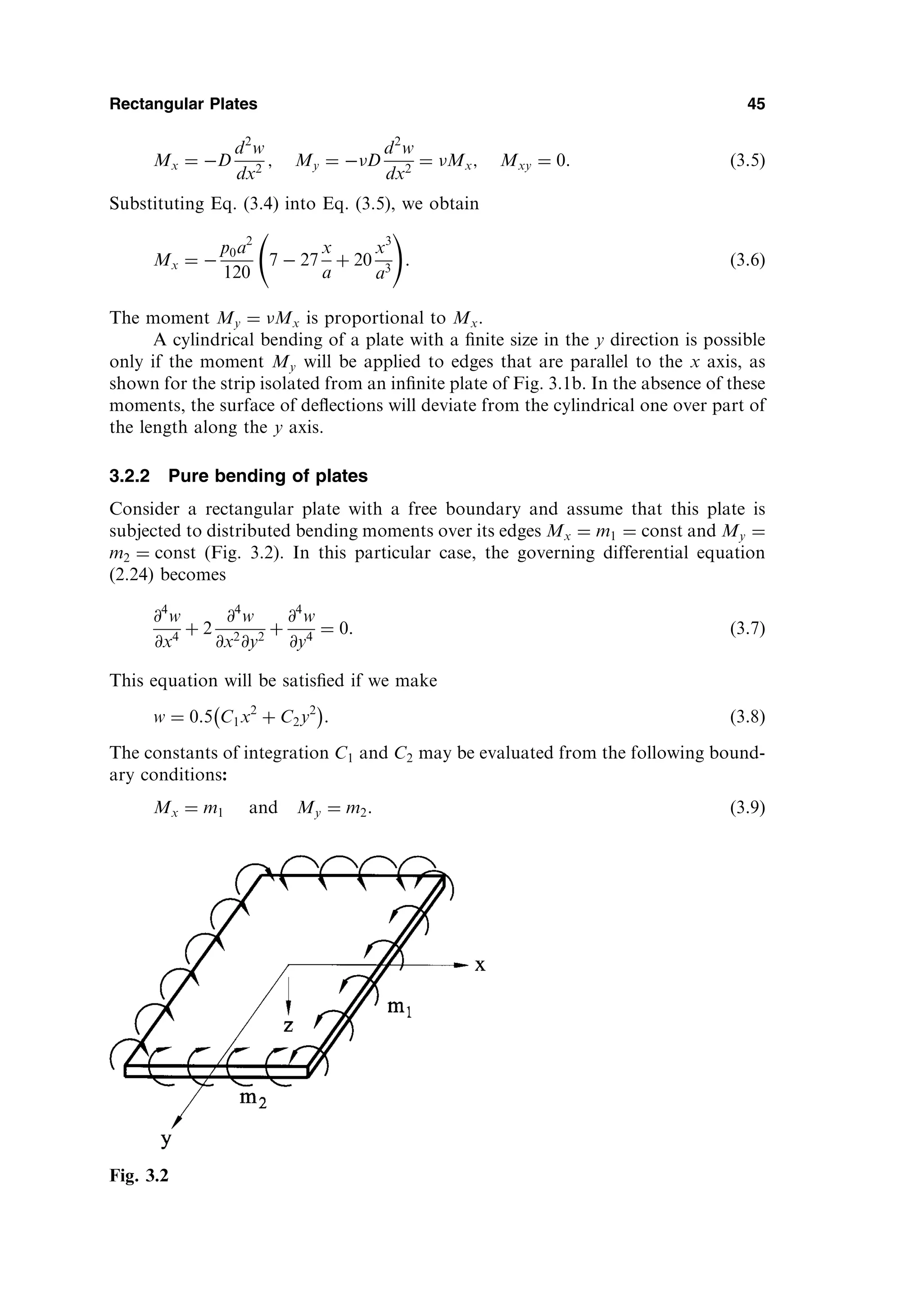
a corner force. Consider, as an example, the case of symmetrically loaded, simply
supported rectangular plate, as shown in Fig. 2.9.
At the corners, x ¼ a and y ¼ b, the above-discussed action of the twisting
moments (because Mxy ¼ Myx) results in
30 Chapter 2
Fig. 2.8
40.
S ¼ 2Mxy¼ 2D 1
ð Þ
@2
w
@x@y
x¼a;y¼b
: ð2:41Þ
Thus, the distributed twisting moments are statically equivalent to the distributed
edge forces @Myx=@x and @Mxy=@y over the plate boundary, as well as to the con-
centrated corner forces, S ¼ 2Mxy for a given rectangular plate. Note that the direc-
tions of the concentrated corner forces, S, are shown in Fig. 2.9 for a symmetrical
downward directed loading of the plate. At the origin of the coordinate system,
taking into account the nature of torsion of an adjacent element, we obtain for
the moment Mxy and, consequently, for the force S, the minus sign. If we rotate
the twisting moment Mxy 0 through 90 , then we obtain at this corner point
(x ¼ 0; y ¼ 0) a downward force S ¼ 2Mxy. At other corner points the signs of
Mxy will alternate, but the above-mentioned corner forces will be directed downward
everywhere for a symmetrical loading of a plate.
The concentrated corner force for plates having various boundary conditions
may be determined similarly. In general, any right angle corner where at least one of
the intersecting boundaries can develop Mxy or Myx will have a corner force. For
instance, when two adjacent plate edges are fixed or free, we have S ¼ 0, since along
these edges no twisting moments exist. If one edge of a plate is fixed and another one
(perpendicular to the fixed edge) is simply supported, then S ¼ Mxy. The case of
non-right angle intersections will be examined later.
It is quite valid to utilize the above replacement of the shear force Qy and
twisting moment Mxy by the effective shear force Vy in the context of the
approximate Kirchhoff’s theory of plate bending, as it was mentioned earlier.
But with respect to a real plate, equating of the effective shear force to zero
does not mean that both the shear force and twisting moment are necessarily
equal to zero. Hence, according to Kirchhoff’s theory, we obtain such a solution
when along a free edge, e.g., y ¼ const, some system of shear stresses yz (corre-
sponding to Qy) and yx (corresponding to Myx) is applied (of course, such a
system of stresses and corresponding to them the stress resultants and stress
couples appear on this free edge). This system is mutually balanced on the
edge y ¼ const and it causes an additional stress field. The latter, however, due
Small-Deflection Plate Bending Theory 31
Fig. 2.9
41.
to Saint-Venant’s principle,decays rapidly as we move away from this edge into
the interior of the plate. The above-mentioned additional stress field cannot be
determined by using the governing differential equation (2.24). Corrections can be
obtained using the plate bending equations with regard to the shear strains xz
and yz and will be discussed in Sec. 7.3. These corrections, as a rule, are neg-
ligible for solid isotropic plates.
(4) Edge x ¼ 0 supported by a beam
The boundary conditions of the type (2.33), (2.35), and (2.37) are called homogeneous
boundary conditions. Nonhomogeneous boundary conditions are commonly used in
many important engineering structures – for example, when a plate is supported by
an edge beam.
Assume that the cross section of the edge beam is symmetrical with respect to
the middle surface of the plate and the edge beam has flexural and torsional rigid-
ities. Since the edge beam and the plate are built monotonically (Fig. 2.10), they must
have the same displacements and slopes.
wb ¼ w x¼0
and #b ¼ # x¼0
or
@w
@x
b
¼
@w
@x x¼0
; ð2:42Þ
where the subscript b refers to the edge beam, and quantities relating to the plate
have no subscripts.
Consider an element dy of the edge beam as a free body, as shown in Fig. 2.10.
Equilibrium conditions of this element result in the following equations:
X
Fz ¼ 0: Qb Vxdy þ Qb þ
dQb
dy
dy ¼ 0
X
My ¼ 0: þ T þ Mxdy T þ
dT
dy
dy
¼ 0 or
Vx ¼
dQb
dy
ð0; yÞ; Mx ¼
dT
dy
ð0; yÞ ðaÞ
where T is the twisting moment in the beam.
As it follows from the beam theory [5]
32 Chapter 2
Fig. 2.10
42.
dQb
dy
ð0; yÞ ¼ EI
ð Þb
@4
wb
@y4
ð0; yÞ and ðbÞ
Tð0; yÞ ¼ GJ
ð Þb
d#b
dy
ð0; yÞ ¼ GJ
ð Þb
@2
wb
@x@y
ð0; yÞ; ðcÞ
where ðEIÞb and ðGJÞb are the flexural rigidity and the torsional stiffness of the beam
cross section, respectively.
Substituting (b) and (c) into Eq. (a) and taking into account the compatibility
conditions (2.42), gives the boundary conditions for the plate edge x ¼ 0 supported
by the beam:
Vx ¼ EI
ð Þb
@4
wb
@y4
x¼0
; Mx ¼ GJ
ð Þb
@3
wb
@x@y2
x¼0
ð2:43aÞ
Using the expressions for Mx and Vx, Eqs. (2.13), (2.39b), and Eqs (2.42), we can
rewrite the boundary conditions (2.43a) in terms of w, as follows:
D
@3
w
@x3
þ ð2 Þ
@3
w
@x@y2
#
¼ EI
ð Þb
@4
w
@y4
x¼0
; D
@2
w
@x2
þ
@2
w
@y2
#
¼ GJ
ð Þb
@3
w
@x@y2
x¼0
:
ð2:43bÞ
Similar expressions can be written for edges y ¼ 0; b.
Let us study the boundary conditions on skew edges. Consider a vertical sec-
tion of the plate whose normal n makes an angle with the x axis (Fig. 2.11a). Take
the origin of the Cartesian coordinate system n (outward normal to the edge) and t
(tangent to the edge) at some point of the edge. In a general case, the normal bending
Mn and twisting Mnt moments, as well the transverse shear force Qn will act at this
section. Figure 2.11b shows the state of stress of a layer of the plate with the
coordinate z 0. The above moments at any point of the skew edge are
Small-Deflection Plate Bending Theory 33
Fig. 2.11
43.
Mn ¼
ð
h=2
h=2
nzdz; Mnt¼
ð
h=2
h=2
ntzdz: ð2:44Þ
The relationship between the stress components shown in Fig. 2.11b is given by [6,7]
n ¼ x cos2
þ y sin2
þ 2xy cos sin ;
nt ¼ xy cos 2 ðx yÞ sin cos :
Substituting the above into Eqs (2.44), integrating over the plate thickness and
taking into account Eqs (2.11), one obtains the following relationships
Mn ¼ Mx cos2
þ My sin2
þ Mxy sin 2 ;
Mnt ¼ Mxy cos 2 ðMx MyÞ sin cos :
ð2:45Þ
The shear force Qn acting at a section of the edge having a normal n can be evaluated
from condition of equilibrium of the plate element shown in Fig. 2.11a, as follows:
Qnds Qxdy Qydx ¼ 0; from which
Qn ¼ Qx cos þ Qy sin :
ð2:46Þ
The effective shear force at a point of the skew edge can be determined similarly to
(2.38), i.e.,
Vn ¼ Qn þ
@Mnt
@t
; ð2:47Þ
where @=@t denotes a differentiation with respect to the tangent of the skew edge.
The boundary conditions discussed above for rectilinear edge can be general-
ized to some curvilinear edge. Let n and t be the outward normal making the angle
with the x axis and tangent to the curvilinear edge at a point of interest (Fig. 2.12).
Then the prescribed boundary conditions (2.33), (2.35), and (2.37), taking into
account (2.47), can be rewritten at an arbitrary point of the above curvilinear
edge, as follows:
34 Chapter 2
Fig. 2.12
44.
(1) Built-in curvilinearedge
w ¼ 0;
@w
@n
¼ 0: ð2:48aÞ
(2) Simply supported edge
w ¼ 0; Mn ¼ 0: ð2:48bÞ
(3) Free curvilinear edge
Mn ¼ 0; Vn ¼ Qn þ
@Mnt
@s
¼ 0: ð2:48cÞ
(4) Curvilinear edge is elastically fixed
w þ 1Vn ¼ 0;
@w
@n
þ 2Mn ¼ 0; ð2:48dÞ
where Mn and Vn are the normal bending moment and the normal effective shear
force, respectively, defined by expressions (2.45) and (2.47). They can also be
expressed in terms of the deflection w using Eqs (2.45)–(2.47) and Eqs (2.13) and
(2.27). In Eqs (2.48) 1 and 2 are some coefficients that characterize a support
compliance.
If adjacent edges of a plate have slopes of the normals 1 and 2 (Fig. 2.13),
then the concentrated force S at a common corner point will be equal to
S ¼ Mnt
ð Þ 1
Mnt
ð Þ 2
: ð2:49Þ
When 1 ¼ 0 and 2 ¼ =2 we will obtain the expression (2.41).
It is observed from the above that the boundary conditions are of the two basic
kinds: geometric or kinematic boundary conditions describe edge constraint pertaining
to deflection or slope; static or natural boundary conditions impose some restrictions
on the internal forces and moments at the edges of the plate. Accordingly, in Eq.
(2.48a) both conditions are kinematic; in Eq. (2.48c) they are both static; and in Eq.
(2.48b) the boundary conditions are mixed.
Small-Deflection Plate Bending Theory 35
Fig. 2.13
45.
2.6 VARIATIONAL FORMULATIONOF PLATE BENDING PROBLEMS
It is known from the theory of elasticity that governing equations for stresses,
strains, and displacements can be represented in the differential form. However,
this is not a unique possible formulation of the problem for finding the stress–strain
field of an elastic body. The problem of determining stresses, strains, and displace-
ments can be reduced to some definite integral of one or another type of these
functions called functionals. Then, the functions themselves (stresses, strains, and
displacements) reflecting a real state of a body can be found from conditions of
extremum for this functional. The mathematical techniques of such an approach is
studied in the division of mathematics called the calculus of variation. Therefore,
some postulates and statements that formulate properties of these functionals in the
theory of elasticity are referred to as variational principles. The latter represent some
basic theorems expressed in the form of integral equalities connecting stresses,
strains, and displacements throughout the volume of a body and based on the
properties of the work done by external and internal forces. A variety of powerful
and efficient approximate methods for analysis of various linear and nonlinear pro-
blems of solid mechanics are based on the variational principles. Some of these
methods will be described further in Chapter 6.
2.6.1 Strain energy of plates
A functional is a scalar quantity depending on some function or several functions, as
from independent variables. The functional can be treated as a function of an infinite
number of independent variables. The subject matter of the calculus of variation is
searching of unknown functions fiðx; y; zÞ that give a maximum (minimum) or sta-
tionary value of a functional. For example,
¼
ð ð
V
ð
F f1ðx; y; zÞ; f2ðx; y; zÞ; . . . ; fnðx; y; zÞ; f 0
1 ðx; y; zÞ; . . . ;
f 0
n ðx; y; zÞ; x; y; z
dV:
The above-mentioned functions for which the functional is maximum (minimum) or
stationary are referred to as extremals of the given functional [8–11].
Let us consider a functional expressing the total potential energy of a deformed
elastic body and the loads acting on it. The total potential energy, , consists of the
strain energy of deformation (the potential of internal forces), U, and the potential
energy of external forces (the potential of external forces), , i.e.,
¼ U þ : ð2:50Þ
By convention, let us assume that the potential energy at the initial, undeformed
state, 0, is zero. Hence, the total energy presents a variation of the energy of
internal and external forces in the transition from initial to deformed states. The
potential energy of a body is measured by the work done by external and internal
forces when this body returns from its final to an initial position (where it was
mentioned above, 0 ¼ 0).
Our study is mainly limited to linearly elastic bodies that dissipate no energy
and have only one equilibrium configuration. We also require that loads keep the
36 Chapter 2
46.
same orientation inspace as they move. Such loads are called conservative. A
mechanical system is called conservative if zero net work is done in carrying the
system around any closed path: that is, in arbitrary changing a configuration and
then restoring it. An extension of this study to nonlinear, or nonconservative, pro-
blems is possible.
First, let us set up an expression for the potential of the internal forces (strain
energy of deformation). This potential is equal to the negative work of the internal
forces, i.e., U ¼ Wi. Since the work done by the internal forces, Wi, is always
negative (because displacements always occur in the opposite direction with respect
to applied internal forces), the strain energy is positive.
The strain energy stored in an elastic body for a general state of stress is given
by [6,7]
U ¼
1
2
ð ð ð
V
xx þ yy þ zz þ xyxy þ xzxz þ yzyz
dV: ð2:51Þ
The integration extends over the entire body volume V. Based upon the assumptions
of Kirchhoff’s small-deflection plate bending theory, the stress components z; xz;
and yz may be omitted. Thus, introducing the generalized Hooke’s law, the above
expression reduces to the following form, involving only stresses and elastic con-
stants,
U ¼
ð ð ð
V
1
2E
2
x þ 2
y 2xy
þ
1 þ
E
2
xy
dV: ð2:52Þ
Substituting for the stress components from Eq. (2.10) into Eq. (2.52) and integrat-
ing it over the thickness of the plate, we obtain
U ¼
1
2
ð ð
A
D
@2
w
@x2
!2
þ
@2
w
@y2
!2
þ 2
@2
w
@x2
@2
w
@y2
þ 2ð1 Þ
@2
w
@x@y
!2
2
4
3
5dA ð2:53Þ
or alternatively
U ¼
1
2
ð ð
A
D
@2
w
@x2
þ
@2
w
@y2
!2
2ð1 Þ
@2
w
@x2
@2
w
@y2
@2
w
@x@y
!2
2
4
3
5
8
:
9
=
;
dA ð2:54Þ
where A is the area of the plate middle surface.
We can also rewrite the expression (2.53) for the strain energy in terms of the
bending and twisting moments, and the corresponding curvatures by the use of Eqs
(2.13). As a result, for plates of a constant thickness the strain energy is
U ¼
1
2
ð ð
A
Mxx þ Myy þ 2Mxyxy
dA: ð2:55Þ
Small-Deflection Plate Bending Theory 37
47.
We observe fromEqs (2.53) and (2.54) that the strain energy is a nonlinear (quad-
ratic) function of deformations. Hence, the principle of superposition is therefore not
valid for the strain energy.
The expressions (2.53) and (2.54) are valid for plates of constant and variable
thickness. It should be noted that the following integral
ð ð
A
@2
w
@x2
@2
w
@y2
@2
w
@x@y
!2
2
4
3
5dA ð2:56Þ
entering in Eq (2.54) is equal to zero for fixed supports and for simply supported
edges of plates, whose contour is traced by straight lines. This statement can be easily
proven by transforming the integral (2.56) over the plate surface into the line integral
over the plate boundary [3].
The potential of external forces, , is defined as the work done by external
forces through the corresponding displacements, assuming that these forces remain
unchanged during the deformation. Further, when a positive displacement occurs,
decreases, so the potential of the external forces is always negative and may be
evaluated as the product of these forces and the corresponding final displacement
components. Determine the potential, p, of the distributed load pðx; yÞ and con-
centrated Pi and Mj forces and moments applied to the middle surface of the plate as
follows:
p ¼
ð ð
A
pðx; yÞwdA þ
X
i
Piwi þ
X
j
Mj#j
2
4
3
5; ð2:57Þ
where wi and #j are the deflection and the slope of the normal at the point of
application of the ith force and jth moment in the plane of the action of this moment,
respectively.
In the expression (2.57) the potential of edge loads, , is not included. These
loads have potentials only if compatible boundary displacements are permitted. In
such cases, the potentials of the edge moments mn; mt and the transverse edge forces
Vn can be expressed as
¼
þ
Vnw þ mn
@w
@n
þ mnt
@w
@t
ds; ð2:58Þ
where @w=@n and @w=@t are the derivatives of w with respect to the outward normal
and the tangent directions, respectively, along the plate boundary to the boundary .
The total potential of the external loads applied to the plate surface and to its
boundary is
¼ p þ ; ð2:59Þ
where p and are given by the expressions (2.57) and (2.58).
Using expressions (2.50), (2.54), (2.57) and (2.58), we can write the total poten-
tial energy of the plate in bending in the Cartesian coordinates as follows
38 Chapter 2
48.
¼
1
2
ð ð
A
D
@2
w
@x2
þ
@2
w
@y2
!2
2ð1 Þ
@2
w
@x2
@2
w
@y2
@2
w
@x@y
!2
2
4
3
5
8
:
9
=
;
dA
ð ð
A
pðx; yÞwdA þ
X
i
Pwi þ
X
j
Mj#jþ
2
4
þ
Vnwn þ mn
@w
@n
þ mnt
@w
@t
ds
3
5;
ð2:60Þ
or alternatively
¼
1
2
ð ð
A
Mxx þ Myy þ 2Mxyxy
dA
ð ð
A
pðx; yÞwdA þ
X
i
Piwi þ
X
j
Mj#jþ
2
4
þ
Vnwn þ mn
@w
@n
þ mnt
@w
@t
ds
3
5:
ð2:61Þ
As is seen from Eq. (2.58) that the value of the total potential energy of
bending of plates is determined by an assignment of deflection w as a function of
independent variables (x and y in the Cartesian coordinate system).
2.6.2 Variational principles
Let us consider some general concepts of the calculus of variation. A variation means
an infinitesimal increment of a function for fixed values of its independent variables.
The variation is designated by the symbol . The variational symbol may be treated
as the differential operator d. The only difference between them lies in the fact that
the symbol refers to some possible variations of a given function while the symbol d
is associated with real variations of the same function. In what follows, only the
following three operations are needed:
dðwÞ
dx
¼
dw
dx
; ðw2
Þ ¼ 2wðwÞ;
ð
ðwÞdx ¼
ð
wdx:
Consider an elastic body in equilibrium. This means that the body subjected
to the maximum values of static (i.e., slowly piled-up) external forces has already
reached its final state of deformation. Now we disturb this equilibrium condition
by introducing small, arbitrary, but kinematically compatible, displacements.
These displacements need not actually take place and need not be infinitesimal.
Only one restriction is imposed on these displacements: they must be compatible
with the support conditions (as discussed later, there are cases when satisfaction
of geometric (or kinematic) boundary conditions is sufficient) and internal com-
patibility of the body. These displacements are called admissible virtual, because
Small-Deflection Plate Bending Theory 39
49.
they are imaginedto take place (i.e., hypothetical), with the actual loads acting at
their fixed values. The admissible virtual displacement produces an admissible
configuration of the body. It follows from the above that virtual displacements
cannot affect the equilibrium of the given system, when the full loads have been
applied. Neither external loads nor internal forces and moments are altered by a
virtual displacement [8–12, 14].
Now we can introduce the general variational principles of solid mechanics.
(a) The Principle of Conservation of Energy
This principle states that the strain energy stored in an elastic body is equal to the work
done by the applied external loads during the loading process, if we assume that there
are no thermal or inertial effects.
(b) The Principle of Virtual Work
The work done by actual forces through a virtual displacement of the actual con-
figuration is called virtual work. It is assumed that during the virtual displacements
all forces are held constant. The virtual work is designated by W.
The principle of virtual work is formulated as follows:
An elastic body is in equilibrium if and only if the total virtual work done by external
and internal forces is zero for any admissible virtual displacements, i.e.,
W ¼ Wi þ We ¼ 0 (2.62)
where Wi and We are the virtual works done by internal and external forces,
respectively. As mentioned earlier, Wi is negative. This principle was first pro-
posed by J. Bernoulli in 1771. It can be interpreted as follows: if a body is in
equilibrium then its resultant force and resultant couple are both zero; so, they
produce no work.
(c) The Principle of Minimum Potential Energy
The principle of minimum potential energy may be looked upon as a specialization
of the principle of virtual work (2.62). Indeed, the potential energy of the internal
forces is equal to the negative work of the internal forces, i.e., U ¼ Wi. On the
other hand, We ¼ . Therefore, we can write the equality (2.62), as follows:
W ¼ U ¼ 0; ð2:63Þ
where U þ ¼ ðU þ Þ ¼ (because can be treated as a differential of a
function) and is the variation in the total potential energy due to introducing
compatible virtual displacements and is given by Eq. (2.60) or Eq. (2.61). Finally, the
equality (2.63) can be written as
¼ 0: ð2:64Þ
This equality expresses the principle of minimum potential energy proposed by
Lagrange.
From calculus, an equality df ¼ 0 means that the function f has an extremum
(or a value corresponding to a point of inflection). It can be shown [9,10] that a
variation of the total potential energy during any admissible virtual displacement
(variation of the displacement) is positive for any stable configuration of equili-
40 Chapter 2
50.
brium. Hence, inthis case, the total potential energy of a given system has a mini-
mum. From the uniqueness theorem [6,7], the problem of the theory of elasticity,
based on assumptions of small displacements and deformations defines only one
equilibrium configuration, and this configuration of equilibrium is stable. Thus, if
the small-deflection theory of an elastic body is being studied, then the potential
energy is a minimum in an equilibrium state. So, the principle of minimum potential
energy, proposed by Lagrange, can be formulated, as follows:
Among all admissible configurations of an elastic body, the actual configuration (that
satisfies static equilibrium conditions) makes the total potential energy, , stationary
with respect to all small admissible virtual displacements. For stable equilibrium, is a
minimum.
Notice that the above principle applies to a conservative system only.
It can be shown that the governing differential equation (2.24) and the bound-
ary conditions (2.48) can be deduced from Lagrange’s variational principle (2.64)
[3,8–12]. However, the key importance of the variational principles discussed above
is that they can be used to obtain approximate solutions of complicated problems of
solid mechanics, in particular, plate-shell bending problems. These are obtained
while avoiding mathematical difficulties associated with integration of differential
equations in partial derivatives. The corresponding methods, called variational meth-
ods and based on the above-mentioned principles, are discussed further in Chapter 6.
More complete information on the variational principles and their application in
mechanics is available in the literature [8–12].
PROBLEMS
2.1 Verify the result given by Eq. (2.18).
2.2 Derive the governing differential equation for deflections of a plate subjected to a
distributed moment load mxðx; yÞ and myðx; yÞ applied to the middle surface.
2.3 Show that at the corner of a polygonal simply supported plate, Mxy ¼ 0 unless the
corner is 90 .
2.4 If a lateral deflection w is a known function of x and y, what are the maximum slope
@w=@n and the direction of axis n with respect to the x axis in terms of @w=@x and
@w=@y?
2.5 Show that the sum of bending curvatures in any two mutually perpendicular directions,
n and t, at any point of the middle surface, is a constant, i.e.,
x þ y ¼ n þ t ¼ const:
2.6 Verify the expression given by Eq. (2.61).
2.7 Derive the expressions for the boundary quantities Mn; Mnt; and Vn in terms of the
deflection w at a regular (smooth) point of the curvilinear contour of the plate using:
(a) the local coordinates n and t where the coordinate n coincides with the direction of
the outward normal and t – with the tangent direction to the boundary; (b) the intrinsic
coordinates n and s, where s, is the arc length over the boundary.
Hint: use the following relations for part (b)
@n
@s
¼
1
t;
@t
@s
¼
1
n
where n and t are the unit vectors of the intrinsic coordinate system directed along the
outward normal and tangent to the boundary, respectively.
Small-Deflection Plate Bending Theory 41
51.
2.8 Derive Eq.(2.24) directly from the third equation of (1.10) by using the relations (2.16)
and (2.17).
2.9 Assume that shear stresses in the plate are distributed according to the parabolic law
for h=2 z h=2. Show that when the expression xz ¼ 6Qx=h3
h=2
ð Þ2
z2
is sub-
stituted into the first relation (2.12) an identity is obtained.
2.10 Prove that the integral (2.56) is equal to zero for fixed supports and for simply sup-
ported edges.
REFERENCES
1. Webster, A.G., Partial Differential Equations of Mathematical Physics, Dover, New
York, 1955.
2. Sommerfeld, A., Partial Differential Equations in Physics, Academic Press, New York,
1948.
3. Timoshenko, S.P. and Woinowsky-Krieger, S., Theory of Plates and Shells, 2nd edn,
McGraw-Hill, New York, 1959.
4. Thomson, W. and Tait, P.G., Treatise on Natural Philosophy, Cambridge University
Press, Cambridge, 1890.
5. Timoshenko, S.P., Strength of Materials, 3rd edn, Van Nostrand Company, New York,
1956.
6. Timoshenko, S.P. and Goodier, J.N., Theory of Elasticity, 3rd edn, McGraw-Hill, New
York, 1970.
7. Prescott, J.J., Applied Elasticity, Dover, New York, 1946.
8. Forray, M.J., Variational Calculus in Science and Engineering, McGraw-Hill, New York,
1968.
9. Lanczos, C., The Variational Principles of Mechanics, The University of Toronto Press,
Toronto, 1964.
10. Hoff, H.I., The Analysis of Structures Based on the Minimal Principles and Principle of
Virtual Displacements, John Wiley and Sons, New York, 1956.
11. Reddy, J.N., Energy and Variational Methods in Applied Mechanics, John Wiley and
Sons, New York, 1984.
12. Washizy, K., Variational Methods in Elasticity and Plasticity, 3rd edn, Pergamon Press,
New York, 1982.
FURTHER READING
Gould, P.L., Analysis of Shells and Plates, Springer-Verlag, New York, Berlin, 1988.
Heins, C.P., Applied Plate Theory for the Engineer, Lexington Books, Lexington,
Massachusetts, 1976.
McFarland, D.E., Smith, B.L. and Bernhart, W.D., Analysis of Plates, Spartan Books, New
York, 1972.
Mansfield, E.H., The Bending and Stretching of Plates, Macmillan, New York, 1964.
Szilard, R., Theory and Analysis of Plates, Prentice-Hall, Inc., Englewood Cliffs, New York,
1974.
Ugural, A.C., Stresses in Plates and Shells, McGraw-Hill, New York, 1981.
Vinson, J.R., The Behavior of Plates and Shells, John Wiley and Sons, New York, 1974.
42 Chapter 2
52.
3
Rectangular Plates
3.1 INTRODUCTION
Webegin the application of the developed plate bending theory with thin rectangular
plates. These plates represent an excellent model for development and as a check of
various methods for solving the governing differential equation (2.24).
In this chapter we consider some mathematically ‘‘exact’’ solutions in the form
of double and single trigonometric series applied to rectangular plates with various
types of supports and transverse loads, plates on an elastic foundation, continuous
plates, etc.
3.2 THE ELEMENTARY CASES OF PLATE BENDING
Let us consider some elementary examples of plate bending of great importance for
understanding how a plate resists the applied loads in bending. In addition, these
elementary examples enable one to obtain closed-form solutions of the governing
differential equation (2.24).
3.2.1 Cylindrical bending of a plate
Consider an infinitely long plate in the y axis direction. Assume that the plate is
subjected to a transverse load which is a function of the variable x only, i.e., p ¼ pðxÞ
(Fig. 3.1a). In this case all the strips of a unit width parallel to the x axis and isolated
from the plate will bend identically. The plate as a whole is found to be bent over the
cylindrical surface w ¼ wðxÞ. Setting all the derivatives with respect to y equal zero in
Eq. (2.24), we obtain the following equation for the deflection:
d4
w
dx4
¼
pðxÞ
D
: ð3:1Þ
43
53.
We have appliedhere the ordinary derivative notation since w depends now
only on the variable x. Equation (3.1) describes a cylindrical bending of thin plates. It
is seen that this equation coincides with the corresponding equation of bending of a
beam if we replace the flexural rigidity of the beam, EI, by the flexural rigidity of a
plate, D. Since D EI, the strip of the unit width within the plate (it is cross-hatched
in Fig. 3.1a) is always stiffer than an isolated beam having the same span and
thickness.
An integration of Eq. (3.1) should present no problems. Let, for example,
p ¼ p0
x
a, then the general solution of Eq. (3.1) is of the following form:
w ¼ wh þ wp ¼ C1 þ C2x þ C3x2
þ C4x3
þ
p0x5
120aD
; ð3:2Þ
where wh is a solution of homogeneous equation (3.1) and wp is a particular solution
depending on the right-hand side of Eq. (3.1), i.e., on a given type of the applied
loading.
The boundary conditions for the plate-strip can be written as follows (Fig.
3.1a)
w ¼ 0jx¼0;
dw
dx
¼ 0
x¼0
and w ¼ 0jx¼a; Mx ¼ D
d2
w
dx2
¼ 0
x¼a
: ð3:3Þ
The constants of integration Ci ði ¼ 1; 2; 3; 4Þ can be evaluated from the
boundary conditions (3.3). Substituting for w from (3.2) into (3.3), we obtain the
following:
C1 ¼ C2 ¼ 0; C3 ¼
7p0a2
240D
; C4 ¼
9p0a
240D
:
Substituting the above into Eq. (3.2), yields Eq. (3.4), as shown below:
w ¼
p0a4
240D
7
x2
a2
9
x3
a3
þ 2
x5
a5
!
ð3:4Þ
This is the equation for the deflection of the plate in cylindrical bending.
The bending moments Mx and My may be obtained from Eqs (2.13) making
all the derivatives of w with respect to y equal zero, i.e.,
44 Chapter 3
Fig. 3.1
54.
Mx ¼ D
d2
w
dx2
;My ¼ D
d2
w
dx2
¼ Mx; Mxy ¼ 0: ð3:5Þ
Substituting Eq. (3.4) into Eq. (3.5), we obtain
Mx ¼
p0a2
120
7 27
x
a
þ 20
x3
a3
!
: ð3:6Þ
The moment My ¼ Mx is proportional to Mx.
A cylindrical bending of a plate with a finite size in the y direction is possible
only if the moment My will be applied to edges that are parallel to the x axis, as
shown for the strip isolated from an infinite plate of Fig. 3.1b. In the absence of these
moments, the surface of deflections will deviate from the cylindrical one over part of
the length along the y axis.
3.2.2 Pure bending of plates
Consider a rectangular plate with a free boundary and assume that this plate is
subjected to distributed bending moments over its edges Mx ¼ m1 ¼ const and My ¼
m2 ¼ const (Fig. 3.2). In this particular case, the governing differential equation
(2.24) becomes
@4
w
@x4
þ 2
@4
w
@x2
@y2
þ
@4
w
@y4
¼ 0: ð3:7Þ
This equation will be satisfied if we make
w ¼ 0:5 C1x2
þ C2y2
: ð3:8Þ
The constants of integration C1 and C2 may be evaluated from the following bound-
ary conditions:
Mx ¼ m1 and My ¼ m2: ð3:9Þ
Rectangular Plates 45
Fig. 3.2
Lewin wunderte sichjetzt nicht mehr, wie während der ersten Zeit
seines Lebens in Moskau, daß zur Fahrt von der Wosdwishenka nach
den Siwzij Wrashki ein Paar starker Pferde in den schweren Wagen
hatten gespannt werden müssen, um diesen durch den kotigen
Schnee ein viertel Werst weit zu bringen, worauf sie vier Stunden
standen und daß er dafür fünf Rubel zahlte. Jetzt erschien ihm das
schon natürlich.
„Laß den Mietkutscher ein Paar Pferde für unseren Wagen
bringen,“ sagte er.
„Zu Diensten.“
Nachdem Lewin auf diese Weise, dank den Verhältnissen der
Stadt, einfach und leicht eine Schwierigkeit geordnet hatte, welche
auf dem Lande soviel überflüssige Mühe und Aufmerksamkeit
erfordert hätte, ging er zur Freitreppe hinaus und rief einen
Mietkutscher; setzte sich in den Wagen und fuhr nach der Nikitskaja.
Unterwegs dachte er nicht mehr an Geld, sondern überlegte, wie er
sich mit dem Petersburger Gelehrten, der sich mit Socialwissenschaft
beschäftigte, bekannt machen und mit ihm über sein Buch sprechen
wollte.
Nur in der allerersten Zeit hatten Lewin in Moskau jene, dem
Landbewohner befremdlichen, eiteln und doch unvermeidlichen
Geldausgaben überrascht, die von allen Seiten von ihm gefordert
wurden. Jetzt hatte er sich jedoch schon an sie gewöhnt. Es ging
ihm in dieser Beziehung so, wie es dem Trinker gehen soll: das erste
Glas ging schwer, das zweite leichter — nach dem dritten aber ging
es wie im Vogelschwarm.
57.
Als Lewin daserste Hundertrubelpapier zum Ankauf der Livree
eines Dieners und eines Portiers wechselte, stellte er sich
unwillkürlich vor, daß diese Livreen, die niemand etwas nützten,
doch unumgänglich erforderlich waren, darnach zu urteilen, wie sich
die Fürstin und Kity verwunderten bei der Andeutung, man könne
auch ohne Livree auskommen — daß diese Livreen ihm zwei
Sommerarbeiter, das heißt, einige dreihundert Arbeitstage von der
Osterwoche bis zu Fastnachten kosteten, von denen jeder voll
schwerer Arbeit vom frühen Morgen bis zum späten Abend war —
und dieses Hundertrubelpapier ging ihm noch schwer vom Herzen.
Das folgende indessen, zum Einkauf von Lebensmitteln zu einem
Essen das er seinen Verwandten gab, das ihn auf achtundzwanzig
Rubel kam, ging, obwohl es in Lewin die Erinnerung daran wachrief,
daß achtundzwanzig Rubel doch neun Tschetwert Hafer waren,
welcher unter Schweiß und Stöhnen gemäht, gebunden,
gedroschen, geworfelt, wieder ausgesät oder aufgeschüttet wurde,
schon leichter fort. Jetzt aber riefen die gewechselten Scheine schon
gar nicht mehr derartige Erwägungen hervor, sondern flogen wie
kleine Vögel davon. Ob die Mühe, welche auf die Erwerbung des
Geldes verwendet worden war, dem Vergnügen, welches der dafür
erkaufte Gegenstand gewährte, wirklich entsprach, diese Erwägung
war schon lange verloren gegangen. Die wirtschaftliche Erwägung,
daß es einen bestimmten Preis giebt, unter welchem man das
Getreide nicht verkaufen kann, war gleichfalls vergessen. Das
Getreide, auf dessen Preis er so lange gehalten hatte, wurde für
fünfzig Kopeken der Tschetwert billiger verkauft, als man einen
Monat vorher dafür gegeben hatte. Selbst die Erwägung, daß man
bei derartigen Ausgaben unmöglich ein ganzes Jahr leben könne,
ohne Schulden zu machen, selbst diese Erwägung hatte keine
Bedeutung mehr für ihn. Nur Eines war nötig; man mußte Geld auf
58.
der Bank haben,ohne daß gefragt wurde, woher es kam, sodaß man
stets wußte, wofür man den nächsten Tag das Rindfleisch kaufen
könnte.
Er hatte nunmehr auch dies bei sich beobachtet: Stets hatte bei
ihm Geld in der Bank gelegen. Jetzt aber war es dort ausgegangen
und er wußte nicht recht, woher nun welches nehmen. Und dies
versetzte ihn, als Kity mit ihm über das Geld sprach, einen
Augenblick in Verlegenheit. Dabei aber hatte er auch keine Zeit,
darüber nachzudenken.
Er fuhr dahin, an Katawasoff und die bevorstehende
Bekanntschaft mit Metroff denkend.
3.
Lewin war mit seiner Ankunft hier wiederum eng mit seinem
ehemaligen Universitätsfreunde, dem Professor Katawasoff in
Verkehr getreten, den er seit der Zeit seiner Verheiratung nicht
wieder gesehen hatte.
Katawasoff war ihm angenehm durch die Klarheit und Einfachheit
seiner Weltanschauung. Lewin glaubte, daß die Klarheit dieser
Weltanschauung Katawasoffs aus der Armut von dessen Natur
hervorgegangen sei, Katawasoff hingegen meinte, daß die
Inkonsequenz in der Denkweise Lewins aus dem Mangel an geistiger
Disciplin bei diesem hervorgehe; aber die Klarheit Katawasoffs war
Lewin willkommen, und der Überfluß der undisciplinierten Gedanken
Lewins war Katawasoff lieb; sie trafen sich gern und debattierten
dann.
59.
Lewin las Katawasoffeinige Stellen aus seinem Werke vor und sie
gefielen diesem. Als gestern Katawasoff Lewin im Kolleg getroffen
hatte, hatte er zu ihm gesagt, daß der bekannte Metroff, dessen
Abhandlung Lewin so gut gefallen hatte, sich in Moskau befinde, und
sehr interessiert sei von dem, was ihm Katawasoff über die Arbeit
Lewins mitgeteilt hatte, daß Metroff morgen, um elf Uhr bei ihm,
und sehr erfreut sein würde, mit ihm bekannt zu werden.
„Ihr lernt entschieden immer besser aussehen, Verehrtester; es
macht einem Freude, Euch zu sehen,“ sagte Katawasoff, Lewin im
kleinen Salon entgegentretend. „Ich hörte die Glocke und dachte,
nicht möglich, daß er zur rechten Zeit käme — nun, wie steht es mit
den Tschernagorzen? Nach der Art des Krieges“ —
„Nun?“ frug Lewin.
Katawasoff teilte ihm in kurzen Worten die letzte Nachricht mit
und machte Lewin, in das Kabinett eintretend, mit einem kleinen,
feisten Manne von sehr angenehmem Äußern bekannt. Dies war
Metroff.
Das Gespräch drehte sich kurze Zeit um Politik, und darum, wie
man in den höchsten Sphären Petersburgs die jüngsten Ereignisse
betrachte.
Metroff teilte ihm aus zuverlässiger Quelle bekannte Worte mit, die
bei dieser Gelegenheit vom Zaren und einem der Minister geäußert
worden sein sollten.
Katawasoff hatte auch als verbürgt erfahren, daß der Zar etwas
ganz anderes gesagt habe. Lewin bemühte sich, eine Situation
herauszuklügeln, nach welcher diese wie jene Worte gesagt worden
60.
sein konnten, unddas Gespräch über den Gegenstand wurde
abgebrochen.
„Der Herr hat auch ein Buch bald fertig geschrieben über die
natürlichen Verhältnisse des Arbeiters in Bezug auf den Boden,“
sagte Katawasoff, „ich bin zwar nicht Spezialist, doch hat es mir als
Naturwissenschaftler gefallen, daß er die Menschheit nicht als etwas
außerhalb der zoologischen Gesetze stehendes auffaßt, sondern im
Gegenteil die Abhängigkeit derselben von ihrer Umgebung erkennt
und in dieser Abhängigkeit die Gesetze ihrer Entwicklung erforscht.“
„Das ist sehr interessant,“ sagte Metroff.
„Ich habe eigentlich nur ein Buch über die Landwirtschaft zu
schreiben begonnen, bin aber unwillkürlich, indem ich mich mit dem
wichtigsten Instrument der Landwirtschaft, dem Arbeiter,
beschäftigte,“ sagte Lewin errötend, „zu vollständig unerwarteten
Resultaten gekommen.“
Und Lewin begann nun vorsichtig, als taste er nach Boden, seine
Anschauung darzulegen.
Er wußte, daß Metroff eine Abhandlung gegen die allgemein
herrschende politisch-ökonomische Wissenschaft geschrieben hatte,
wußte aber nicht, bis zu welchem Grade er hoffen konnte, auf
Teilnahme für seine neuen Anschauungen bei ihm zu stoßen, und
konnte dies auch nicht an dem klugen und ruhigen Gesicht des
Gelehrten erraten.
„Aber worin seht Ihr die besonderen Eigenschaften des russischen
Arbeiters?“ sagte Metroff, „in seinen zoologischen Eigenschaften,
sozusagen, oder in den Verhältnissen, in denen er sich befindet?“
61.
Lewin sah, daßin dieser Frage schon ein Gedanke ausgesprochen
war, mit welchem er nicht in Einklang stand, doch fuhr er fort, seine
Idee zu entwickeln, welche darin bestand, daß der russische Arbeiter
einen im Vergleich zu dem der Arbeiter anderer Völker vollkommen
eigenartigen Blick für sein Land besitze, und beeilte sich, um seine
Behauptung zu stützen, hinzuzufügen, daß nach seiner Meinung,
dieser Blick des russischen Volkes herrühre aus dem Bewußtsein
seines Berufes, die ungeheuren, noch unbebauten Gegenden im
Osten bevölkern zu müssen.
„Es ist leicht möglich, in einen Irrtum zu verfallen, wenn man
einen Schluß auf die allgemeine Bestimmung eines Volkes macht,“
sagte Metroff, Lewin unterbrechend. „Die Lage des Arbeiters wird
stets von dessen Beziehungen zu Boden und Kapital abhängen.“
Ohne Lewin noch zu gestatten, seine Idee ganz auszusprechen,
begann nun Metroff, ihm die Eigenart seiner Lehre zu erklären.
Worin die Eigenart dieser Lehre bestand, begriff Lewin nicht, weil er
sich gar nicht bemühte, sie zu begreifen; er sah, daß Metroff, ebenso
wie die anderen, trotz seiner Abhandlung, in welcher die
Wissenschaft der Nationalökonomen gestürzt wurde, auf die
Situation des russischen Arbeiters doch nur vom Gesichtspunkt des
Kapitals des Arbeiterlohnes und der Rente blickte.
Obwohl er nun zugestehen mußte, daß in dem östlichen, dem
größten Teile Rußlands, die Rente noch gleich Null war, daß der
Arbeitslohn für neun Zehntel der achtzig Millionen Einwohner nur die
Ernährung in sich selbst ausdrückte, und ein Kapital noch nicht
anders vorhanden sei, als in Gestalt von primitivsten Hilfsmitteln, so
blickte er doch lediglich von diesem Standpunkte aus auf die
gesamten Arbeiter, obwohl er in vielem gleichwohl nicht mit den
62.
Nationalökonomen übereinstimmte, undhielt seine neue Theorie
vom Arbeitslohn aufrecht, welche er Lewin entwickelte.
Dieser hörte nur ungern zu und opponierte anfangs. Er wollte
Metroff unterbrechen, um ihm seine Idee zu äußern, die nach seiner
Meinung eine weitere Erklärung überflüssig machte, aber nachdem
er sich überzeugt hatte, daß sie beide in so verschiedenem Grade die
Sache betrachteten, daß niemals Einer den Anderen verstehen
würde, opponierte er nicht mehr, und hörte nur noch zu.
Ungeachtet dessen, das für ihn jetzt schon gar nicht mehr
interessant war, was Metroff sprach, verspürte er doch ein gewisses
Vergnügen, indem er ihm zuhörte. Seiner Eigenliebe wurde dadurch
geschmeichelt, daß ihm ein so gelehrter Mann so gern, mit so großer
Aufmerksamkeit und solchem Zutrauen zu seiner Kenntnis über den
Gegenstand, bisweilen mit einem einzigen Wink auf eine ganze Seite
der Sache deutend, seine Gedanken aussprach.
Er schrieb dies seiner Würde zu, ohne zu wissen, daß Metroff in
der Unterhaltung mit allen seinen Bekannten besonders gern von
jenem Gegenstande mit jedem Menschen, der ihm neu bekannt
wurde, sprach; daß er überhaupt gern mit jedermann über eine
Sache, die ihn beschäftigte und ihm selbst noch unklar war, redete.
„Doch ich werde mich verspätigen,“ sagte Katawasoff, nach der
Uhr blickend, nachdem Metroff seine Darlegung soeben beendet
hatte. „Ja, es ist heute Sitzung in der Gesellschaft der Freunde zum
Gedächtnis des fünfzigjährigen Jubiläums Swintitschs,“ antwortete er
auf Lewins Frage. „Ich habe mich an Peter Iwanowitsch gemacht,
und habe versprochen, über seine Arbeiten in der Zoologie zu lesen.
Kommt mit mir, es ist sehr interessant.“
63.
„In der That,es ist Zeit,“ sagte Metroff. „Kommt mit uns, und,
wenn Ihr wollt, von da aus, mit zu mir. Ich wünschte sehr, von Eurer
Arbeit weiter zu hören.“
„Nein; das wird nicht gehen; sie ist noch unvollendet. Aber in die
Sitzung komme ich sehr gern mit.“
„Wie, Verehrtester, habt Ihr gehört? Er gab eine ganz eigene
Meinung zum besten,“ sagte Katawasoff, im Nebenzimmer den Frack
anlegend.
Es begann ein Gespräch über die Universitätsfrage. Die
Universitätsfrage bildete einen sehr wichtigen Gegenstand während
dieses Winters in Moskau. Drei alte Professoren im Senat hatten die
Meinungen jüngerer nicht acceptiert; und diese vertraten nun eine
eigene Ansicht.
Diese Ansicht war entsetzlich nach dem Urteile der Einen, sie war
sehr einfach und richtig nach dem der Anderen, und die Professoren
hatten sich in zwei Lager gespalten.
Die Einen, zu denen Katawasoff gehörte, sahen auf der
gegnerischen Seite niedrige Verleumdung und Betrug; die Anderen
Kinderei und Mißachtung der Autorität.
Lewin hatte, obwohl er dem Universitätsverband nicht angehörte,
schon mehrmals während seines Aufenthalts in Moskau von dieser
Angelegenheit gehört und darüber gesprochen, und sich in dieser
Beziehung seine eigene Meinung gebildet. Er nahm Teil an dem
Gespräch, welches noch auf der Straße fortgesetzt wurde, als alle
drei nach dem Gebäude der alten Universität gingen.
64.
Die Sitzung hatteschon begonnen. An einem Tische, welcher mit
Tuch gedeckt war und hinter dem sich Katawasoff und Metroff
niederließen, saßen sechs Herren, und einer von ihnen, der sich
dicht über eine Handschrift beugte, las etwas.
Lewin setzte sich auf einen der leeren Stühle, welche um den
Tisch herum standen, und frug flüsternd einen dort sitzenden
Studenten, was man lese.
Mit einem mißvergnügten Blick auf Lewin antwortete dieser:
„Eine Biographie ist es.“
Obwohl sich nun Lewin für die Biographie eines Gelehrten gerade
nicht interessierte, hörte er doch unwillkürlich zu und erfuhr so
manches Interessante und Neue über das Leben des berühmten
Gelehrten.
Als der Lektor geendet hatte, dankte ihm der Vorsitzende und las
die ihm für das Jubiläum eingesandten Verse des Dichters Ment vor,
nebst einigen Worten des Dankes für diesen.
Darauf las Katawasoff mit seiner lauten, schreienden Stimme seine
Schrift über die Gelehrtenthätigkeit des Jubilars.
Nachdem Katawasoff geendet hatte, blickte Lewin auf die Uhr und
gewahrte, daß es schon zwei Uhr sei; er überlegte, daß er bis zum
Konzert Metroff sein Werk nicht werde vorlesen können, und
verspürte dazu auch gar keine Lust.
Während der Zeit des Lesens hatte er nur an die stattgehabte
Unterredung gedacht, und es war ihm jetzt klar, daß, obwohl
vielleicht auch die Ideen Metroffs ihre Bedeutung hatten, seine Ideen
65.
doch ebenfalls einesolche besaßen, und aufklären und zu Etwas
führen könnten, wofern nur ein jeder für sich auf dem auserwählten
Wege arbeite, während aus einer Veränderung dieser beiden Ideen
nichts hervorgehen könne.
Nachdem sich Lewin entschlossen hatte, die Einladung Metroffs
abzulehnen, begab er sich beim Schluß der Sitzung zu diesem hin.
Metroff machte Lewin mit dem Präsidenten bekannt, mit welchem er
über politische Neuigkeiten sprach. Hierbei erzählte Metroff dem
Präsidenten das Nämliche, was er Lewin erzählt hatte, während
Lewin die gleichen Bemerkungen machte, die er schon heute
Vormittag geäußert hatte; zur Abwechslung indessen sprach er auch
seine eigene Meinung mit aus, die ihm gerade einfiel. Hierauf
begann wiederum das Gespräch über die Universitätsfrage. Da Lewin
indessen alles das schon gehört hatte, beeilte er sich, Metroff zu
sagen, er bedaure, von seiner Einladung nicht Gebrauch machen zu
können, empfahl sich und fuhr zu Lwoff.
4.
Lwoff, der mit Nataly, der Schwester Kitys verheiratet war, hatte
sein ganzes Leben in den Residenzen und im Auslande zugebracht,
wo er auch erzogen worden war und als Diplomat gedient hatte.
Im vergangenen Jahre hatte er die diplomatische Carriere
aufgegeben, nicht infolge einer Unannehmlichkeit — er hatte niemals
mit jemand Unannehmlichkeiten gehabt — und war in das Hofgericht
nach Moskau übergetreten, um seinen beiden Söhnen eine bessere
Erziehung angedeihen zu lassen.
66.
Trotz des schärfstenGegensatzes in den Gewohnheiten und
Anschauungen, sowie darin, daß Lwoff auch älter als Lewin war,
waren beide in diesem Winter in engen Verkehr miteinander
getreten und hatten sich gegenseitig liebgewonnen.
Lwoff befand sich daheim, und Lewin trat ohne Anmeldung bei
ihm ein. Lwoff war im Hausrock mit Gürtel, und saß in Halbschuhen
von sämischem Leder in einem Lehnstuhl, durch das Pincenez mit
blauen Gläsern ein Buch lesend, welches auf einem Lesepult lag,
während er, auf der Hut vor der abfallenden Asche, mit der schönen
Hand eine bis zur Hälfte aufgerauchte Cigarre hielt.
Sein schönes, feines und jugendliches Gesicht, welchem die
lockigen, glänzenden silbernen Haare noch mehr den Ausdruck
angestammten Adels verliehen, erglänzte von einem Lächeln, als er
Lewin erblickte.
„Ausgezeichnet! Ich wollte schon zu Euch schicken! Nun, was
macht Kity! Setzt Euch hierher, da ist es behaglicher,“ er stand auf
und bewegte einen Rollstuhl herbei.
„Habt Ihr schon das letzte Cirkular im ‚Journal de St. Petersbourg‘
gelesen? Ich finde es vortrefflich,“ sagte er mit etwas französischem
Accent.
Lewin teilte ihm mit, was er von Katawasoff vernommen hatte,
und was man in Petersburg spräche, und berichtete, nachdem er
über die Politik gesprochen hatte, von seiner Bekanntschaft mit
Metroff und seiner Exkursion in die Sitzung. Lwoff interessierte dies
sehr.
67.
„Ich beneide Euch,daß Ihr Zutritt zu dieser interessanten
Gelehrtenwelt habt,“ sagte er, und ging dann, wie gewöhnlich
sogleich zu der ihm bequemeren französischen Sprache über. „Ich
habe allerdings leider auch keine Zeit; denn mein Dienst sowohl, als
die Beschäftigung mit meinen Kindern beraubt mich derselben; dann
aber scheue ich mich nicht, zu bekennen, daß meine Bildung allzu
mangelhaft ist.“
„Das glaube ich nicht,“ antwortete Lewin lächelnd, und, wie
gewöhnlich, voll Erbarmen mit dieser niedrigen Meinung von sich
selbst, die durchaus nicht dem Wunsche, bescheiden zu erscheinen
oder zu sein, entsprang, sondern vollständig aufrichtig war.
„Ach, gewiß doch! Ich fühle es jetzt, wie wenig gebildet ich bin.
Selbst zur Erziehung der Kinder muß ich viel wieder an meinem
Gedächtnis auffrischen, ja geradezu lernen! Denn trotzdem, daß
Lehrer da sind, muß auch ein Aufseher da sein, sowie in Eurer
Ökonomie Arbeiter nötig sind nebst einem Inspektor. Da lese ich
eben“ — er zeigte auf die Grammatik Buslajeffs, welche auf dem
Lesepult lag, „das fordert man von Mischa, und es ist doch so
schwierig — erklärt mir dies. Hier sagt er“ —
Lewin wollte ihm erklären, daß man dies nicht verstehen könne,
sondern lernen müsse, doch Lwoff stimmte dem nicht bei.
„Ihr lacht darüber!“ sagte er.
„Im Gegenteil, Ihr könnt Euch nicht vorstellen, wie ich, im Hinblick
auf Euch, stets studiere, was mir auch bevorsteht, die Erziehung von
Kindern!“
„Nun, aber das Lernen taugt doch nichts,“ sagte Lwoff.
68.
„Ich kann nursagen,“ antwortete Lewin, „daß ich nie besser
erzogene Kinder gesehen habe, als die Euren, und keine besseren
Kinder wünschte, als die Euren sind.“
Lwoff hielt augenscheinlich an sich, seine Freude zu zeigen, aber
er erglänzte doch von einem Lächeln.
„Wenn sie nur besser werden als ich, das ist alles, was ich
wünsche. Ihr kennt noch nicht die ganze Mühe,“ begann er, „mit den
Knaben, welche, wie die meinen, in diesem Leben im Auslande
verwildert waren.“
„Ihr holt alles ein. Es sind ja so befähigte Kinder, und was die
Hauptsache ist — sie haben eine moralische Erziehung. Das ist es,
was ich studiere, wenn ich Eure Kinder anblicke.“
„Ihr sagt, eine moralische Erziehung. Man kann sich nicht
vorstellen, wie schwer diese ist! Kaum habt Ihr die eine Seite
bekämpft, so wachsen andere hervor und es beginnt ein neuer
Kampf. Hätte man nicht die Stützen in der Religion — wißt Ihr noch,
wir haben zusammen darüber gesprochen — so würde kein Vater
mit seinen Kräften allein, ohne diese Hilfe, erziehen können.“
Dieses Lewin stets interessierende Gespräch wurde durch den
Eintritt der zur Ausfahrt angekleideten, schönen Nataly
Aleksandrowna, unterbrochen.
„Ah, ich habe gar nicht gewußt, daß Ihr hier seid,“ sagte sie,
augenscheinlich nicht mit Bedauern, sondern vielmehr erfreut, daß
sie dieses, ihr schon längst bekannte, langweilige Gespräch
unterbrochen hatte. „Was macht Kity? Ich esse heute bei Euch.
69.
Weißt du Arseny,“wandte sie sich an ihren Gatten, „du nimmst den
Wagen.“
Unter den beiden Gatten begann nun ein Gespräch, wie sie den
Tag verleben wollten. Da der Gatte mit jemand im Amte
zusammenkommen, die Gattin aber in das Konzert und in die
öffentliche Sitzung des südöstlichen Komitees fahren mußte, so war
viel zu beschließen und zu überlegen.
Lewin, als unabhängiger Mann, mußte Teil an diesen Plänen
nehmen, und es ward beschlossen, daß er mit Nataly in das Konzert
und in die öffentliche Sitzung fuhr, von da aus den Wagen nach dem
Comptoir zu Arseniy sende und dieser Nataly abholen und mit zu
Kity nehmen solle — oder, wenn er mit seinen Geschäften noch nicht
fertig wäre, den Wagen zurückschicke und Lewin mit ihr fahre.
„Er beschämt mich ganz,“ sagte Lwoff zu seiner Frau, „er
versichert mir, daß unsere Kinder vorzüglich sind, während ich doch
weiß, daß sie soviel Fehler haben.“
„Arseniy geht bis ins Extrem, ich sage es immer,“ bemerkte seine
Gattin. „Wenn man Vollkommenheiten suchen will, so wird man nie
zufrieden werden, und Papa sagt die Wahrheit damit, daß es, als
man uns noch erzog, nur ein einziges Mittel gab — man steckte uns
ins Entresol; während die Eltern in der Bel-Etage wohnten; jetzt
hingegen möchten die Eltern in die Rumpelkammer und die Kinder in
die Bel-Etage! Die Eltern möchten jetzt schon gar nicht mehr selbst
leben, sondern nur noch für ihre Kinder.“
„Aber wie, wenn dies das Angenehmere wäre?“ sagte Lwoff, mit
seinem schönen Lächeln, ihren Arm berührend. „Wer dich nicht
70.
kennt, wird glauben,du seist keine Mutter, sondern eine
Stiefmutter.“
„Nein; das Extrem ist nie gut,“ sagte Nataly ruhig, sein
Papiermesser auf den Tisch an den dafür bestimmten Platz legend.
„Nun kommt einmal her, ihr Musterkinder,“ sagte Lwoff zu seinen
eintretenden hübschen Knaben, welche, Lewin begrüßend, zu ihrem
Vater traten, offenbar in dem Wunsche, ihn nach etwas zu fragen.
Lewin wollte mit ihnen reden und hören, was sie dem Vater zu
sagen hätten, aber Nataly begann mit ihm zu sprechen und soeben
trat auch ein Kollege Lwoffs im Amte, Machotin, in Hofuniform ein,
um mit Lwoff zusammen jemand zu treffen; es begann ein eifriges
Gespräch über die Herzogowina, die Fürstin Korzynska, die Duma
und den plötzlichen Tod der Apraksina.
Lewin hatte den ihm gegebenen Auftrag ganz vergessen. Er
erinnerte sich desselben erst beim Verlassen des Vorzimmers.
„Ach, Kity hat mir ja anvertraut, ich möchte Etwas mit Euch
betreffs Oblonskiys besprechen,“ sagte er, als Lwoff auf der Treppe
stehen blieb, indem er sein Weib und ihn hinausbegleitete.
„Ja, ja, maman wünscht, daß wir, les beaux-frères, ihn
vornehmen,“ sagte er errötend, „aber weshalb wohl ich dabei sein
soll?“ —
„So werde ich ihn vornehmen,“ sagte die Lwowa lächelnd, das
Ende des Gesprächs abwartend; „doch jetzt kommt!“
5.
71.
In der Matineeführte man zwei sehr interessante Novitäten vor.
Die eine war eine Phantasie „König Lear in der Steppe“, die andere
ein Quartett, dem Andenken Bachs gewidmet. Beide Stücke waren
neu und von originellem Geiste und Lewin wünschte sich eine
Meinung über sie zu bilden. Nachdem er seine Schwägerin nach
deren Stuhl begleitet hatte, trat er an eine Säule und nahm sich vor,
so aufmerksam und gewissenhaft als möglich zuzuhören. Er
bemühte sich, nicht abzuschweifen und den Eindruck in sich zu
beinträchtigen, indem er auf die Armbewegungen des Kapellmeisters
in der weißen Halsbinde blickte, die stets die musikalische
Aufmerksamkeit so unangenehm ablenkten, oder auf die Damen in
ihren Hüten, welche sich geflissentlich für das Konzert die Ohren mit
Bändern zugebunden hatten, oder auf alle jene Personen, die
entweder mit nichts beschäftigt, oder von den verschiedensten
Interessen, nur nicht dem für Musik, eingenommen waren.
Er bemühte sich, den Begegnungen mit Musikkennern und
Schwätzern aus dem Wege zu gehen, und stand nur vor sich
niederblickend und lauschte. Doch je mehr er von der Phantasie
König Lear hörte, um so ferner fühlte er sich der Möglichkeit gerückt,
sich selbst eine bestimmte Meinung zu bilden.
Unaufhörlich begann es, als bereite sich der Ausdruck einer
musikalischen Empfindung vor, sogleich aber fiel derselbe in
Trümmer von neuen Ansätzen zu musikalischen Phrasen
auseinander, bisweilen sogar einfach in durch nichts als die Laune
des Komponisten verbundene, aber außerordentlich komplizierte
Klänge.
Aber gerade die Unterbrechungen dieser musikalischen Phrasen,
die bisweilen gut waren, zeigten sich als unangenehm, weil sie
72.
vollständig unerwartet unddurch nichts vorbereitet erschienen.
Frohsinn und Trauer, Verzweiflung und Zartheit oder Triumph
erschienen ohne jede innere Berechtigung, gleichsam wie die
Gefühle eines Wahnsinnigen; und ebenso wie bei einem
Wahnsinnigen, vergingen sie auch wieder unerwartet.
Lewin hatte während der ganzen Zeit der Aufführung das Gefühl
eines Tauben, welcher auf Tanzende schaut. Er war in vollständiger
Ungewißheit, nachdem das Stück geendet hatte, und fühlte große
Ermüdung von der gespannten, durch nichts gelohnten
Aufmerksamkeit. Von allen Seiten wurde lautes Händeklatschen
vernehmbar. Alles erhob sich und begann herumzulaufen um sich zu
unterhalten.
Im Wunsche, nach dem Eindruck anderer seinen Zweifel
aufzuklären, begann auch Lewin zu gehen, um Kenner zu suchen,
und war erfreut, als er einen namhaften Musikkenner im Gespräch
mit dem ihm bekannten Peszoff erblickte.
„Wunderbar!“ sagte der tiefe Baß Peszoffs.
„Guten Tag, Konstantin Dmitritsch. Ganz besonders formgerecht
und monumental, sozusagen; und wie reich an Farben ist jene
Stelle, in welcher man die Annäherung Cordelias fühlt, wo die Frau,
‚das ewig Weibliche‘ wie der Deutsche sagt, in den Kampf mit dem
Schicksal tritt. Nicht wahr?“
„Nun, inwiefern war denn da gerade Cordelia?“ frug Lewin
schüchtern; er hatte vollständig vergessen, daß die Phantasie König
Lear in der Steppe ausdrücken solle.
73.
„Es zeigt sichCordelia — hier!“ sagte Peszoff, mit den Fingern auf
den atlasglänzenden Zettel schlagend, den er in der Hand hielt und
Lewin nun hinreichte.
Jetzt erst erinnerte sich Lewin des Titels der Phantasie und beeilte
sich nun, die Verse Shakespeares in der russischen Übersetzung zu
lesen, welche auf der Rückseite des Programms gedruckt standen.
„Ohne dies kann man freilich nicht folgen,“ sagte Peszoff, sich zu
Lewin wendend, da der Herr mit welchem er sich unterhalten hatte,
gegangen war, und er mit niemand mehr zu sprechen hatte.
Im Zwischenakt entspann sich zwischen Lewin und Peszoff ein
Streit über die Vorzüge und Mängel der Wagnerschen Musikrichtung.
Lewin wies nach, daß der Irrtum Wagners und aller seiner
Nachfolger darin bestehe, daß hier die Musik in das Gebiet einer
fremdartigen Kunst übergehen wolle, daß auch die Poesie irre, wenn
sie die Züge eines Gesichts beschreibe, was die Malerei zu thun
hätte, und führte als Beispiel eines solchen Irrtums jenen Bildhauer
an, welcher die Schatten der poetischen Gestalten, die rings um die
Figur des Dichters auf dem Piedestal aufragten, in Marmor zu bilden
gedachte.
„Diese Schatten werden ebensowenig Schatten für den Bildhauer
sein, daß sie sich sogar an der Leiter anhalten können,“ sagte Lewin.
Der Satz gefiel ihm, doch er konnte sich nicht entsinnen, ob er ihn
nicht schon früher einmal ausgesprochen hatte, gerade gegen
Peszoff, und geriet daher, nachdem er ihn geäußert, in Verlegenheit.
Peszoff hingegen wies nach, daß die Kunst einheitlich sei und ihre
höchsten Offenbarungen nur in der Vereinigung aller ihrer Arten
erreichen könne.
74.
Die zweite Nummerdes Konzerts konnte Lewin nicht mehr hören.
Peszoff, der neben ihm stehen geblieben war, hatte fast die ganze
Zeit mit ihm gesprochen, indem er dieses Stück wegen seiner
übermäßigen geschmackswidrigen, unvermittelten Einfachheit den
Praeraphaeliten in der Malerei verglich.
Beim Hinausgehen begegnete Lewin noch vielen Bekannten, mit
welchen er über Politik, über Musik und gemeinsame Bekannte
sprach, unter anderen traf er auch den Grafen Bolj, dessen Besuch
er gänzlich vergessen hatte.
„Nun, so fahrt nur gleich hin,“ sagte die Lwowa zu ihm, der er dies
mitgeteilt hatte, „vielleicht empfängt man Euch nicht und Ihr kommt
dann zu mir in die Sitzung. Ihr werdet mich da schon noch treffen.“
6.
„Man empfängt wohl nicht?“ sagte Lewin, in den Flur des Hauses
der Gräfin Bolj tretend.
„Man empfängt, bitte,“ antwortete der Portier, ihm resolut den Pelz
abnehmend.
„Ist das unangenehm,“ dachte Lewin, mit einem Seufzer den
einen Handschuh abstreifend und seinen Hut glättend. „Weshalb
komme ich denn eigentlich? Was soll ich denn mit ihnen reden?“
Durch den ersten Salon schreitend, traf Lewin in der Thür die
Gräfin Bolj, welche mit geschäftigem und ernstem Ausdruck dem
Diener einen Befehl erteilte.
75.
Als sie Lewinerblickte, lächelte sie und nötigte ihn in den
folgenden, kleinen Salon, aus welchem Stimmen vernehmbar waren.
In diesem Salon saßen auf Lehnstühlen die beiden Töchter der
Gräfin und ein, Lewin bekannter, Moskauer Oberst. Lewin näherte
sich ihnen, grüßte, und ließ sich neben dem Diwan nieder, den Hut
auf dem Knie haltend.
„Wie ist das Befinden Eurer Frau? Waret Ihr im Konzert? Wir
konnten nicht! Mama mußte bei einer Totenmesse gegenwärtig
sein.“
„Ja, ich habe gehört — welch ein plötzlicher Todesfall,“ sagte
Lewin.
Die Gräfin kam, setzte sich auf den Diwan und frug gleichfalls
nach seiner Frau und dem Konzert.
Lewin antwortete und wiederholte die Frage nach dem plötzlichen
Tode der Apraksina.
„Sie war überhaupt stets von schwacher Gesundheit.“
„Waret Ihr gestern in der Oper?“
„Ja, ich war da.“
„Die Lucca war sehr gut.“
„Ja, sehr gut,“ sagte er und begann, da es ihm ganz gleichgültig
war, was man von ihm denken mochte, zu wiederholen, was er
hundertmal schon über die Eigentümlichkeit des Talentes der
Sängerin gehört hatte. Die Gräfin Bolj stellte sich, als höre sie zu. Als
76.
Welcome to ourwebsite – the perfect destination for book lovers and
knowledge seekers. We believe that every book holds a new world,
offering opportunities for learning, discovery, and personal growth.
That’s why we are dedicated to bringing you a diverse collection of
books, ranging from classic literature and specialized publications to
self-development guides and children's books.
More than just a book-buying platform, we strive to be a bridge
connecting you with timeless cultural and intellectual values. With an
elegant, user-friendly interface and a smart search system, you can
quickly find the books that best suit your interests. Additionally,
our special promotions and home delivery services help you save time
and fully enjoy the joy of reading.
Join us on a journey of knowledge exploration, passion nurturing, and
personal growth every day!
ebookbell.com


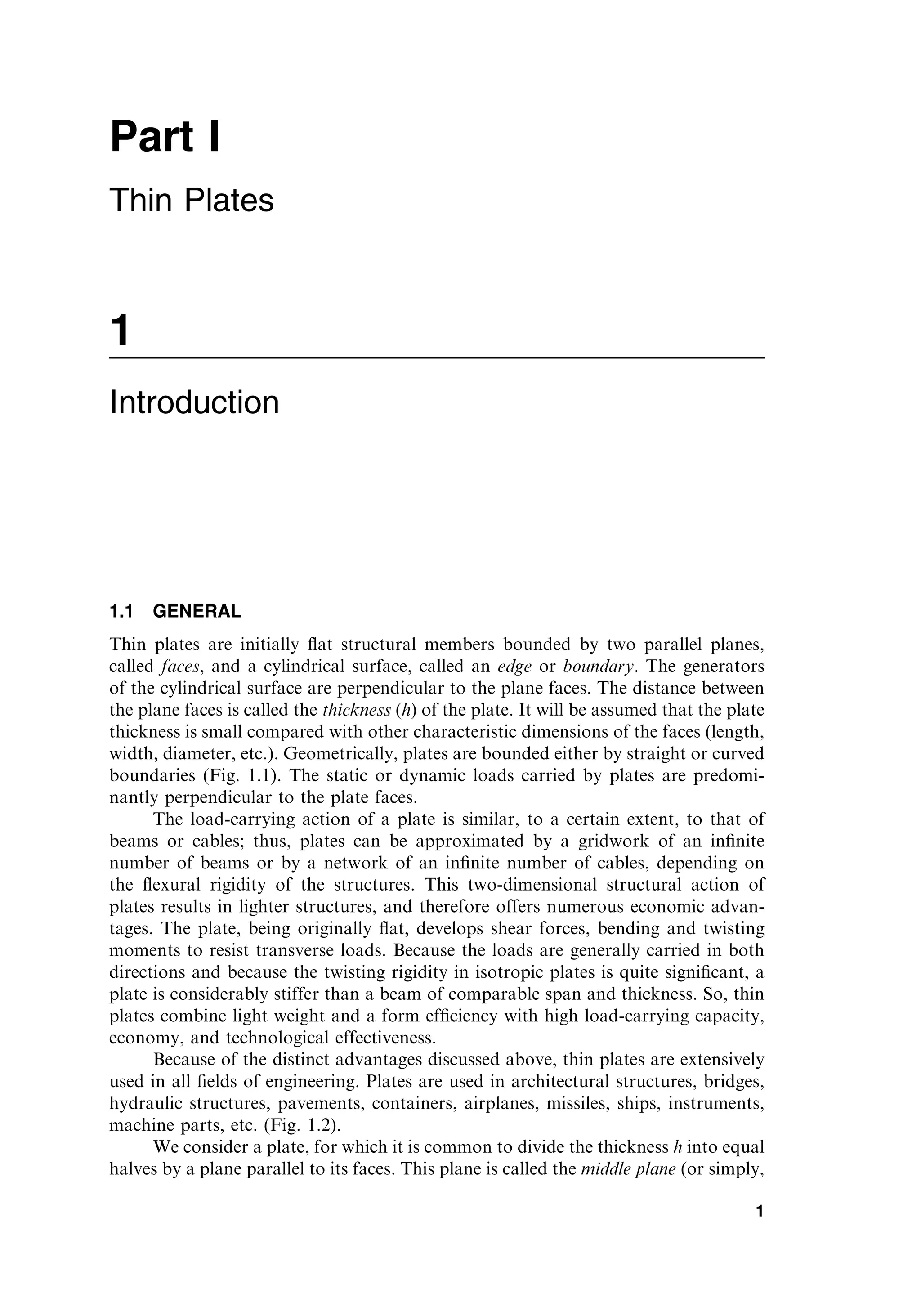
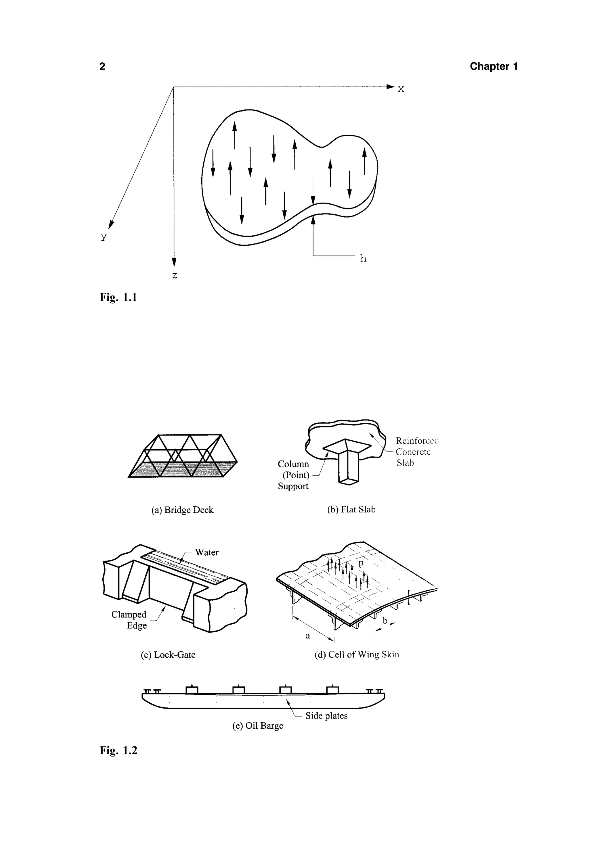
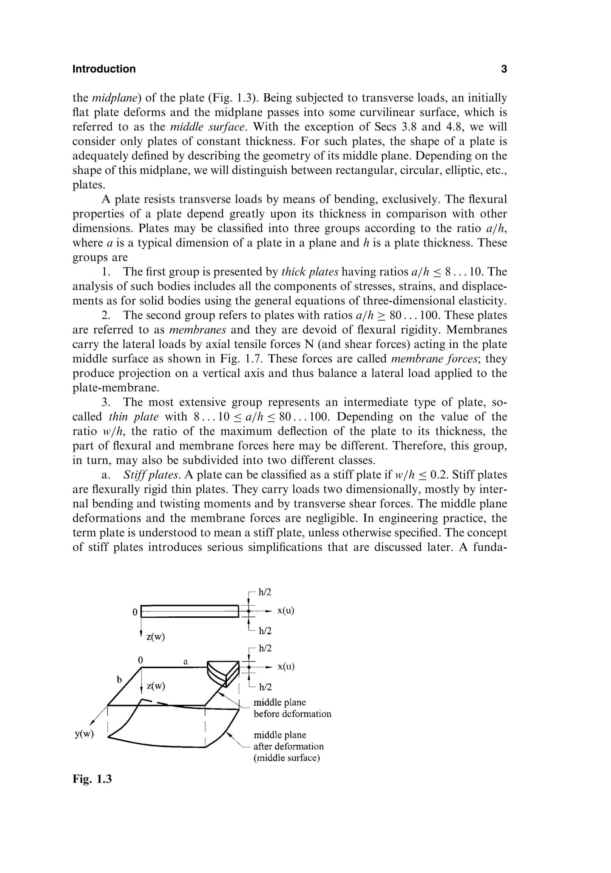
![mental feature of stiff plates is that the equations of static equilibrium for a plate
element may be set up for an original (undeformed) configuration of the plate.
b. Flexible plates. If the plate deflections are beyond a certain level,
w=h 0:3, then, the lateral deflections will be accompanied by stretching of the
middle surface. Such plates are referred to as flexible plates. These plates repre-
sent a combination of stiff plates and membranes and carry external loads by the
combined action of internal moments, shear forces, and membrane (axial) forces.
Such plates, because of their favorable weight-to-load ratio, are widely used by
the aerospace industry. When the magnitude of the maximum deflection is con-
siderably greater than the plate thickness, the membrane action predominates. So,
if w=h 5, the flexural stress can be neglected compared with the membrane
stress. Consequently, the load-carrying mechanism of such plates becomes of
the membrane type, i.e., the stress is uniformly distributed over the plate
thickness.
The above classification is, of course, conditional because the reference of the
plate to one or another group depends on the accuracy of analysis, type of loading,
boundary conditions, etc.
With the exception of Sec. 7.4, we consider only small deflections of thin plates,
a simplification consistent with the magnitude of deformation commonly found in
plate structures.
1.2 HISTORY OF PLATE THEORY DEVELOPMENT
The first impetus to a mathematical statement of plate problems, was probably done
by Euler, who in 1776 performed a free vibration analysis of plate problems [1].
Chladni, a German physicist, discovered the various modes of free vibrations
[2]. In experiments on horizontal plates, he used evenly distributed powder, which
formed regular patterns after induction of vibration. The powder accumulated along
the nodal lines, where no vertical displacements occurred. J. Bernoulli [3] attempted
to justify theoretically the results of these acoustic experiments. Bernoulli’s solution
was based on the previous work resulting in the Euler–D.Bernoulli’s bending beam
theory. J. Bernoulli presented a plate as a system of mutually perpendicular strips at
right angles to one another, each strip regarded as functioning as a beam. But the
governing differential equation, as distinct from current approaches, did not contain
the middle term.
4 Chapter 1
Fig. 1.4](https://image.slidesharecdn.com/438696-250518120012-4586dedb/75/Thin-Plates-And-Shells-Theory-Analysis-And-Applications-1st-Theodor-Krauthammer-13-2048.jpg)
![The French mathematician Germain developed a plate differential equation
that lacked the warping term [4]; by the way, she was awarded a prize by the Parisian
Academy in 1816 for this work. Lagrange, being one of the reviewers of this work,
corrected Germain’s results (1813) by adding the missing term [5]; thus, he was the
first person to present the general plate equation properly.
Cauchy [6] and Poisson [7] were first to formulate the problem of plate bending
on the basis of general equations of theory of elasticity. Expanding all the character-
istic quantities into series in powers of distance from a middle surface, they retained
only terms of the first order of smallness. In such a way they obtained the governing
differential equation for deflections that coincides completely with the well-known
Germain–Lagrange equation. In 1829 Poisson expanded successfully the Germain–
Lagrange plate equation to the solution of a plate under static loading. In this
solution, however, the plate flexural rigidity D was set equal to a constant term.
Poisson also suggested setting up three boundary conditions for any point on a free
boundary. The boundary conditions derived by Poisson and a question about the
number and nature of these conditions had been the subject of much controversy
and were the subject of further investigations.
The first satisfactory theory of bending of plates is associated with Navier [8],
who considered the plate thickness in the general plate equation as a function of
rigidity D. He also introduced an ‘‘exact’’ method which transformed the differential
equation into algebraic expressions by use of Fourier trigonometric series.
In 1850 Kirchhoff published an important thesis on the theory of thin plates
[9]. In this thesis, Kirchhoff stated two independent basic assumptions that are now
widely accepted in the plate-bending theory and are known as ‘‘Kirchhoff’s hypoth-
eses.’’ Using these assumptions, Kirchhoff simplified the energy functional of 3D
elasticity theory for bent plates. By requiring that it be stationary he obtained the
Germain-Lagrange equation as the Euler equation. He also pointed out that there
exist only two boundary conditions on a plate edge. Kirchhoff’s other significant
contributions are the discovery of the frequency equation of plates and the intro-
duction of virtual displacement methods in the solution of plate problems.
Kirchhoff’s theory contributed to the physical clarity of the plate bending theory
and promoted its widespread use in practice.
Lord Kelvin (Thomson) and Tait [10] provided an additional insight relative to
the condition of boundary equations by converting twisting moments along the edge
of a plate into shearing forces. Thus, the edges are subject to only two forces: shear
and moment.
Kirchhoff’s book was translated by Clebsh [11]. That translation contains
numerous valuable comments by de Saint-Venant: the most important being the
extension of Kirchhoff’s differential equation of thin plates, which considered, in a
mathematically correct manner, the combined action of bending and stretching.
Saint-Venant also pointed out that the series proposed by Cauchy and Poissons as
a rule, are divergent.
The solution of rectangular plates, with two parallel simple supports and the
other two supports arbitrary, was successfully solved by Levy [12] in the late 19th
century.
At the end of the 19th and the beginning of the 20th centuries, shipbuilders
changed their construction methods by replacing wood with structural steel. This
change in structural materials was extremely fruitful in the development of various
Introduction 5](https://image.slidesharecdn.com/438696-250518120012-4586dedb/75/Thin-Plates-And-Shells-Theory-Analysis-And-Applications-1st-Theodor-Krauthammer-14-2048.jpg)
![plate theories. Russian scientists made a significant contribution to naval architec-
ture by being the first to replace the ancient trade traditions with solid mathematical
theories. In particular, Krylov [13] and his student Bubnov [14] contributed exten-
sively to the theory of thin plates with flexural and extensional rigidities. Bubnov laid
the groundwork for the theory of flexible plates and he was the first to introduce a
modern plate classification. Bubnov proposed a new method of integration of differ-
ential equations of elasticity and he composed tables of maximum deflections and
maximum bending moments for plates of various properties. Then, Galerkin devel-
oped this method and applied it to plate bending analysis. Galerkin collected numer-
ous bending problems for plates of arbitrary shape in a monograph [15].
Timoshenko made a significant contribution to the theory and application of
plate bending analysis. Among Timoshenko’s numerous important contributions are
solutions of circular plates considering large deflections and the formulation of
elastic stability problems [16,17]. Timoshenko and Woinowsky-Krieger published
a fundamental monograph [18] that represented a profound analysis of various
plate bending problems.
Extensive studies in the area of plate bending theory and its various applica-
tions were carried out by such outstanding scientists as Hencky [19], Huber [20], von
Karman [21,22], Nadai [23], Föppl [24].
Hencky [19] made a contribution to the theory of large deformations and the
general theory of elastic stability of thin plates. Nadai made extensive theoretical and
experimental investigations associated with a check of the accuracy of Kirchhoff’s
plate theory. He treated different types of singularities in plates due to a concen-
trated force application, point support effects, etc. The general equations for the
large deflections of very thin plates were simplified by Föppl who used the stress
function acting in the middle plane of the plate. The final form of the differential
equation of the large-deflection theory, however, was developed by von Karman. He
also investigated the postbuckling behavior of plates.
Huber, developed an approximate theory of orthotropic plates and solved
plates subjected to nonsymmetrical distributed loads and edge moments. The
bases of the general theory of anisotropic plates were developed by Gehring [25]
and Boussinesq [26]. Lekhnitskii [27] made an essential contribution to the develop-
ment of the theory and application of anisotropic linear and nonlinear plate analysis.
He also developed the method of complex variables as applied to the analysis of
anisotropic plates.
The development of the modern aircraft industry provided another strong
impetus toward more rigorous analytical investigations of plate problems. Plates
subjected to in-plane forces, postbuckling behavior, and vibration problems (flutter),
stiffened plates, etc., were analyzed by various scientists and engineers.
E. Reissner [28] developed a rigorous plate theory which considers the defor-
mations caused by the transverse shear forces. In the former Soviet Union the works
of Volmir [29] and Panov [30] were devoted mostly to solution of nonlinear plate
bending problems.
The governing equation for a thin rectangular plate subjected to direct com-
pressive forces Nx was first derived by Navier [8]. The buckling problem for a simply
supported plate subjected to the direct, constant compressive forces acting in one
and two directions was first solved by Bryan [31] using the energy method. Cox [32],
Hartmann [33], etc., presented solutions of various buckling problems for thin
6 Chapter 1](https://image.slidesharecdn.com/438696-250518120012-4586dedb/75/Thin-Plates-And-Shells-Theory-Analysis-And-Applications-1st-Theodor-Krauthammer-15-2048.jpg)
![rectangular plates in compression, while Dinnik [34], Nadai [35], Meissner [36], etc.,
completed the buckling problem for circular compressed plates. An effect of the
direct shear forces on the buckling of a rectangular simply supported plate was
first studied by Southwell and Skan [37]. The buckling behavior of a rectangular
plate under nonuniform direct compressive forces was studied by Timoshenko and
Gere [38] and Bubnov [14]. The postbuckling behavior of plates of various shapes
was analyzed by Karman et al. [39], Levy [40], Marguerre [41], etc. A comprehensive
analysis of linear and nonlinear buckling problems for thin plates of various shapes
under various types of loads, as well as a considerable presentation of available
results for critical forces and buckling modes, which can be used in engineering
design, were presented by Timoshenko and Gere [38], Gerard and Becker [42],
Volmir [43], Cox [44], etc.
A differential equation of motion of thin plates may be obtained by applying
either the D’Alambert principle or work formulation based on the conservation of
energy. The first exact solution of the free vibration problem for rectangular plates,
whose two opposite sides are simply supported, was achieved by Voight [45]. Ritz
[46] used the problem of free vibration of a rectangular plate with free edges to
demonstrate his famous method for extending the Rayleigh principle for obtaining
upper bounds on vibration frequencies. Poisson [7] analyzed the free vibration equa-
tion for circular plates. The monographs by Timoshenko and Young [47], Den
Hartog [48], Thompson [49], etc., contain a comprehensive analysis and design con-
siderations of free and forced vibrations of plates of various shapes. A reference
book by Leissa [50] presents a considerable set of available results for the frequencies
and mode shapes of free vibrations of plates could be provided for the design and for
a researcher in the field of plate vibrations.
The recent trend in the development of plate theories is characterized by a
heavy reliance on modern high-speed computers and the development of the most
complete computer-oriented numerical methods, as well as by introduction of more
rigorous theories with regard to various physical effects, types of loading, etc.
The above summary is a very brief survey of the historical background of the
plate bending theory and its application. The interested reader is referred to special
monographs [51,52] where this historical development of plates is presented in detail.
1.3 GENERAL BEHAVIOR OF PLATES
Consider a load-free plate, shown in Fig.1.3, in which the xy plane coincides with the
plate’s midplane and the z coordinate is perpendicular to it and is directed down-
wards. The fundamental assumptions of the linear, elastic, small-deflection theory of
bending for thin plates may be stated as follows:
1. The material of the plate is elastic, homogeneous, and isotropic.
2. The plate is initially flat.
3. The deflection (the normal component of the displacement vector) of the
midplane is small compared with the thickness of the plate. The slope of
the deflected surface is therefore very small and the square of the slope is
a negligible quantity in comparison with unity.
4. The straight lines, initially normal to the middle plane before bending,
remain straight and normal to the middle surface during the deformation,
Introduction 7](https://image.slidesharecdn.com/438696-250518120012-4586dedb/75/Thin-Plates-And-Shells-Theory-Analysis-And-Applications-1st-Theodor-Krauthammer-16-2048.jpg)
![and the length of such elements is not altered. This means that the vertical
shear strains xz and yz are negligible and the normal strain z may also
be omitted. This assumption is referred to as the ‘‘hypothesis of straight
normals.’’
5. The stress normal to the middle plane, z, is small compared with the
other stress components and may be neglected in the stress–strain rela-
tions.
6. Since the displacements of a plate are small, it is assumed that the middle
surface remains unstrained after bending.
Many of these assumptions, known as Kirchhoff’s hypotheses, are analogous to
those associated with the simple bending theory of beams. These assumptions result
in the reduction of a three-dimensional plate problem to a two-dimensional one.
Consequently, the governing plate equation can be derived in a concise and straight-
forward manner. The plate bending theory based on the above assumptions is
referred to as the classical or Kirchhoff’s plate theory. Unless otherwise stated, the
validity of the Kirchhoff plate theory is assumed throughout this book.
1.4 SURVEY OF ELASTICITY THEORY
The classical theories of plates and shells are an important application of the theory
of elasticity, which deals with relationships of forces, displacements, stresses, and
strains in an elastic body. When a solid body is subjected to external forces, it
deforms, producing internal strains and stresses. The deformation depends on the
geometrical configuration of the body, on applied loading, and on the mechanical
properties of its material. In the theory of elasticity we restrict our attention to linear
elastic materials; i.e., the relationships between stress and strain are linear, and the
deformations and stresses disappear when the external forces are removed. The
classical theory of elasticity assumes the material is homogeneous and isotropic,
i.e., its mechanical properties are the same in all directions and at all points.
The present section contains only a brief survey of the elasticity theory that will
be useful for the development of the plate theory. All equations and relations will be
given without derivation. The reader who desires to review details is urged to refer to
any book on elasticity theory – for example [53–55].
1.4.1 Stress at a point: stress tensor
Consider an elastic body of any general shape subjected to external loads which are
in equilibrium. Then, consider a material point anywhere in the interior of the body.
If we assign a Cartesian coordinate frame with axes x, y, and z, as shown in Fig. 1.5,
it is convenient to assign an infinitesimal element in the form of parallelepiped
(dx; dy; dz), with faces parallel to the coordinate planes. Stresses acting on the
faces of this element describe the intensity of the internal forces at a point on a
particular face. These stresses can be broken down into a normal component (normal
stress) and tangent component (shear stress) to the particular face. As a result, the
three stress components, denoted by xx; xy; xz; . . . ; will act on each face of the
element. The subscript notation for the stress components is interpreted as follows:
the first subscript indicates the direction of an outer normal to the face on which the
stress component acts; the second subscript relates to the direction of the stress itself.
8 Chapter 1](https://image.slidesharecdn.com/438696-250518120012-4586dedb/75/Thin-Plates-And-Shells-Theory-Analysis-And-Applications-1st-Theodor-Krauthammer-17-2048.jpg)
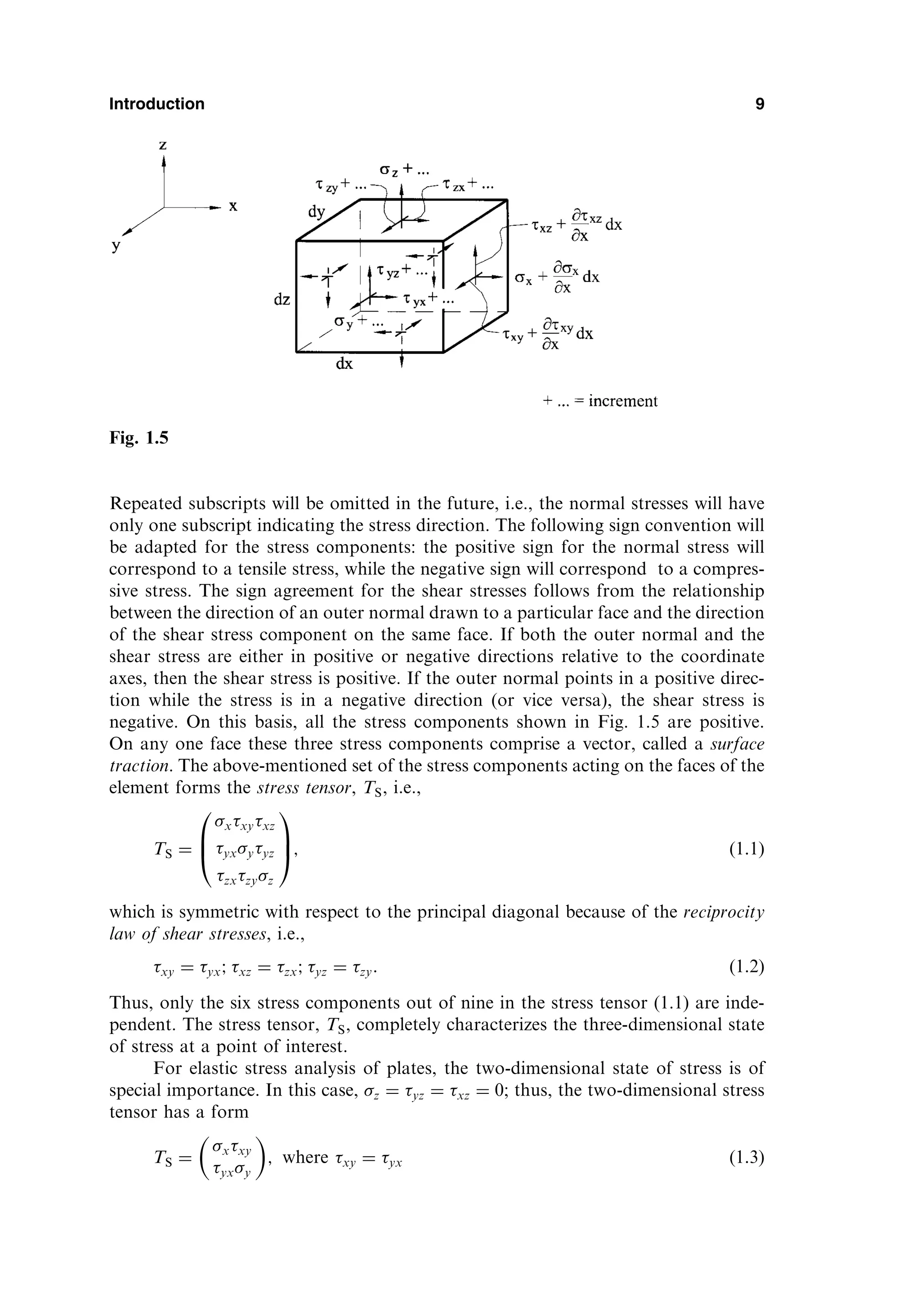
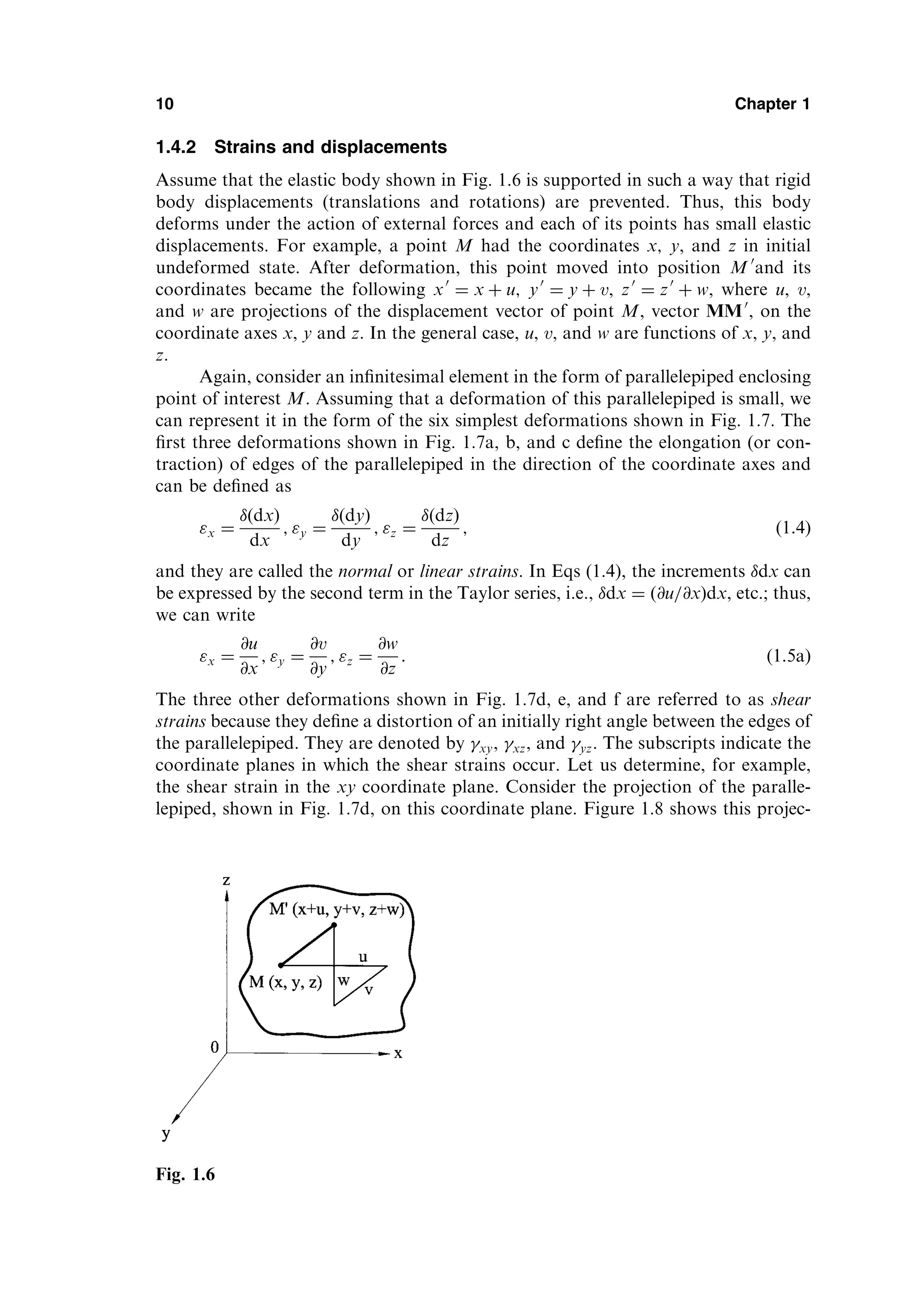
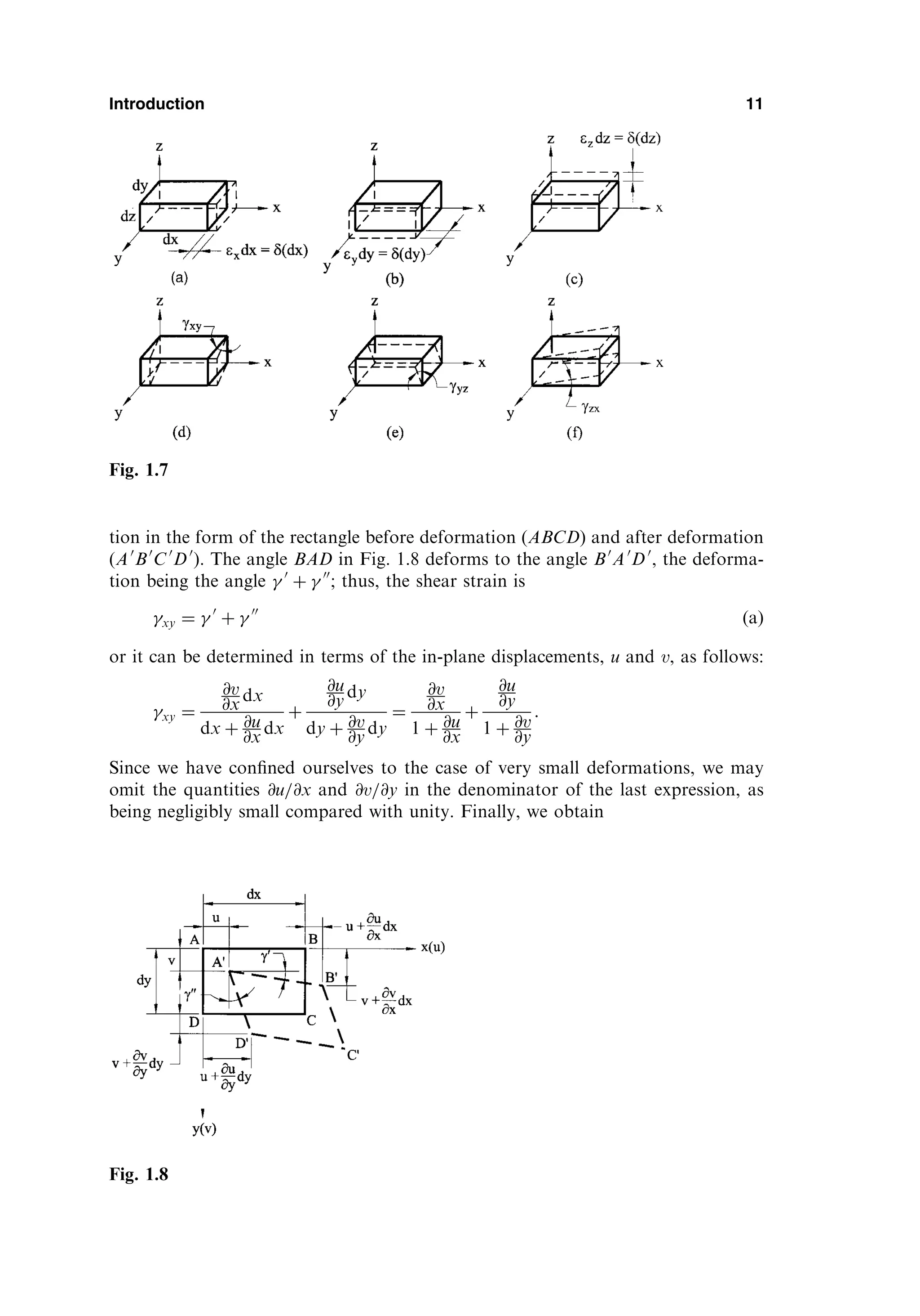
![xy ¼
@v
@x
þ
@u
@y
: ðbÞ
Similarly, we can obtain xz and yz. Thus, the shear strains are given by
xy ¼
@u
@y
þ
@v
@x
; xz ¼
@u
@z
þ
@w
@x
; yz ¼
@v
@z
þ
@w
@y
: ð1:5bÞ
Similar to the stress tensor (1.1) at a given point, we can define a strain tensor as
TD ¼
x
1
2
xy
1
2
xz
1
2
yx y
1
2
yz
1
2
zx
1
2
zy z
0
B
B
B
B
B
@
1
C
C
C
C
C
A
: ð1:6Þ
It is evident that the strain tensor is also symmetric because of
xy ¼ yx; xz ¼ zx; yz ¼ zy ð1:7Þ
1.4.3 Constitutive equations
The constitutive equations relate the stress components to strain components. For
the linear elastic range, these equations represent the generalized Hooke’s law. In the
case of a three-dimensional isotropic body, the constitutive equations are given by
[53].
x ¼
1
E
x y þ z
; y ¼
1
E
y x þ z
ð Þ
; z ¼
1
2
z y þ x
;
ð1:8aÞ
xy ¼
1
G
xy; xz ¼
1
G
xz; yz ¼
1
G
yz; ð1:8bÞ
where E, , and G are the modulus of elasticity, Poisson’s ratio, and the shear
modulus, respectively. The following relationship exists between E and G:
G ¼
E
2ð1 þ Þ
ð1:9Þ
1.4.4 Equilibrium equations
The stress components introduced previously must satisfy the following differential
equations of equilibrium:
@x
@x
þ
@xy
@y
þ
@xz
@z
þ Fx ¼ 0;
@y
@y
þ
@yx
@x
þ
@yz
@z
þ Fy ¼ 0;
@z
@z
þ
@zx
@x
þ
@zy
@y
þ Fz ¼ 0;
ð1:10Þ
12 Chapter 1](https://image.slidesharecdn.com/438696-250518120012-4586dedb/75/Thin-Plates-And-Shells-Theory-Analysis-And-Applications-1st-Theodor-Krauthammer-21-2048.jpg)
![where Fx; Fy; and Fz are the body forces (e.g., gravitational, magnetic forces). In
deriving these equations, the reciprocity of the shear stresses, Eqs (1.7), has been
used.
1.4.5 Compatibility equations
Since the three equations (1.10) for six unknowns are not sufficient to obtain a
solution, three-dimensional stress problems of elasticity are internally statically inde-
terminate. Additional equations are obtained to express the continuity of a body.
These additional equations are referred to as compatibility equations. In Eqs (1.5) we
have related the six strain components to the three displacement components.
Eliminating the displacement components by successive differentiation, the follow-
ing compatibility equations are obtained [53–55]:
@2
x
@y2
þ
@2
y
@x2
¼
@2
xy
@x@y
;
@2
y
@z2
þ
@2
z
@y2
¼
@2
yz
@y@z
; ð1:11aÞ
@2
z
@x2
þ
@2
x
@z2
¼
@2
xz
@x@z
;
@
@z
@yz
@x
þ
@xz
@y
@xy
@z
¼ 2
@2
z
@x@y
;
@
@x
@xz
@y
þ
@xy
@z
@yz
@x
¼ 2
@2
x
@y@z
; ð1:11bÞ
@
@y
@xy
@z
þ
@yz
@x
@xz
@y
¼ 2
@2
y
@x@z
:
For a two-dimensional state of stress (z ¼ 0, xz ¼ yz ¼ 0), the equilibrium condi-
tions (1.10) become
@x
@x
þ
@xy
@y
þ Fx ¼ 0;
@y
@y
þ
@yx
@x
þ Fy ¼ 0;
ð1:12Þ
and the compatibility equation is
@2
x
@y2
þ
@2
y
@x2
¼
@2
xy
@x@y
xz ¼ yz ¼ z ¼ 0
: ð1:13Þ
We can rewrite Eq. (1.13) in terms of the stress components as follows
@2
@x2
þ
@2
@y2
!
x þ y
¼ 0: ð1:14Þ
Introduction 13](https://image.slidesharecdn.com/438696-250518120012-4586dedb/75/Thin-Plates-And-Shells-Theory-Analysis-And-Applications-1st-Theodor-Krauthammer-22-2048.jpg)
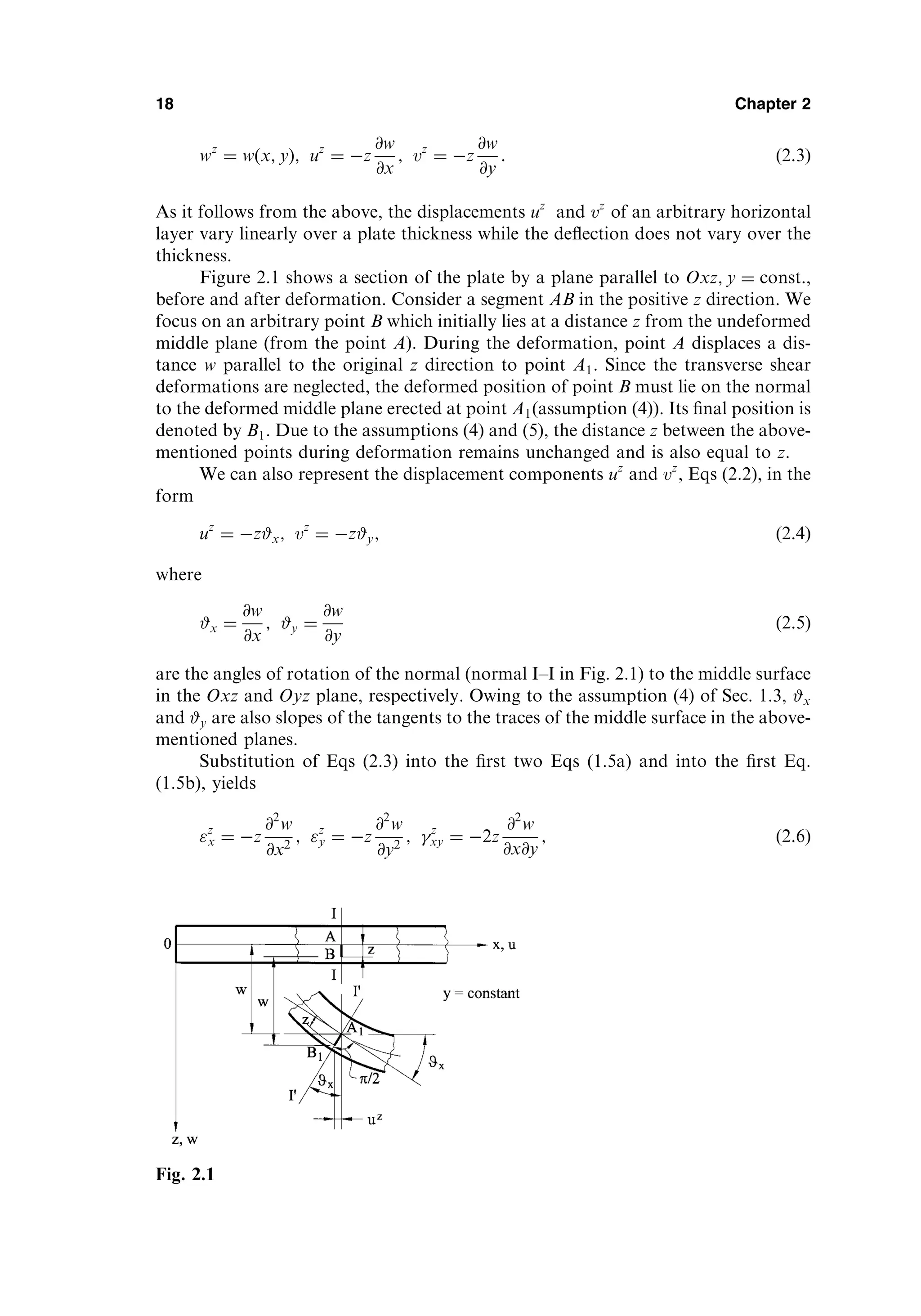
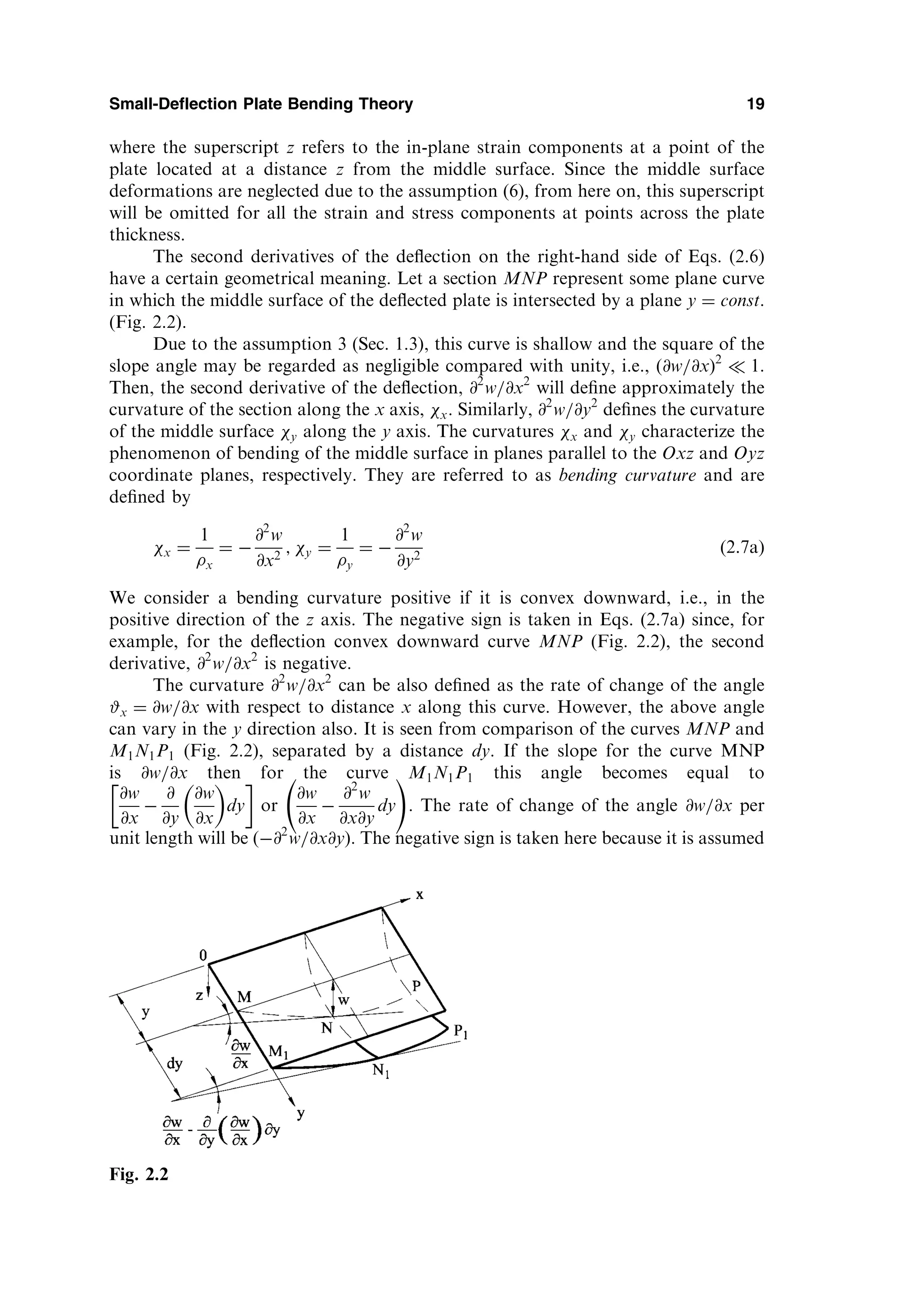
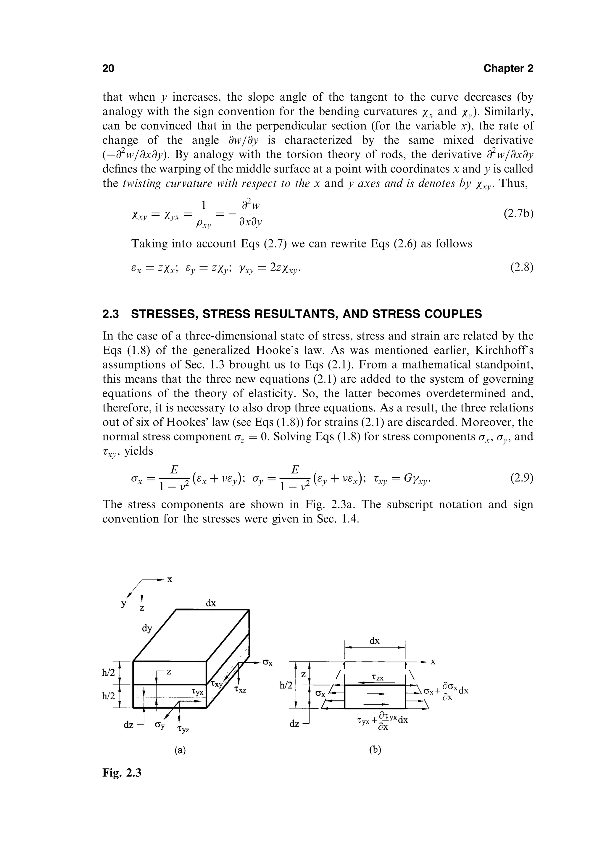
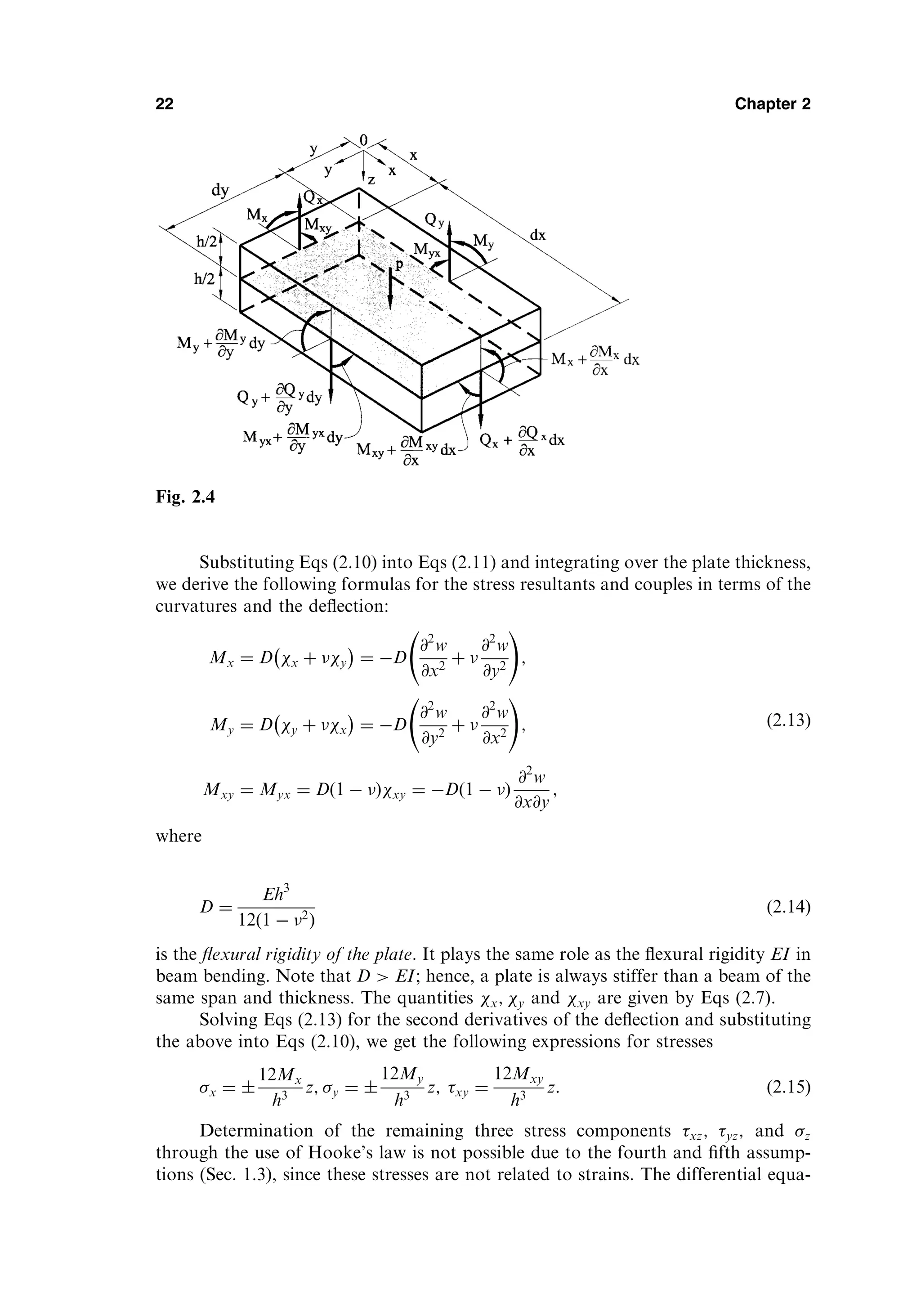
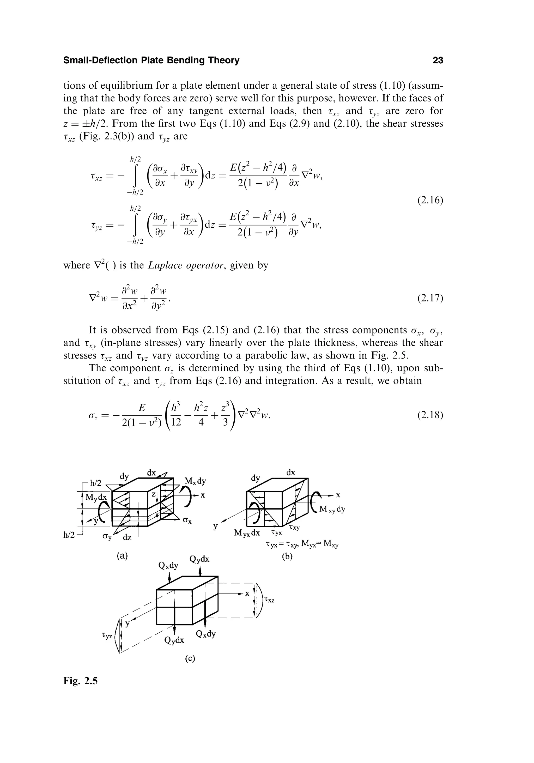
![Qy ¼
@Mxy
@x
þ
@My
@y
ð2:22bÞ
Here it has been taken into account that Mxy ¼ Myx: Substituting Eqs (2.22) into Eq.
(2.19), one finds the following:
@2
Mx
@x2
þ 2
@2
Mxy
@x@y
þ
@2
My
@y2
¼ pðx; yÞ: ð2:23Þ
Finally, introduction of the expressions for Mx; My; and Mxy from Eqs (2.13) into
Eq. (2.23) yields
@4
w
@x4
þ 2
@4
w
@x2
@y2
þ
@4
w
@y4
¼
p
D
: ð2:24Þ
This is the governing differential equation for the deflections for thin plate bending
analysis based on Kirchhoff’s assumptions. This equation was obtained by Lagrange
in 1811. Mathematically, the differential equation (2.24) can be classified as a linear
partial differential equation of the fourth order having constant coefficients [1,2].
Equation (2.24) may be rewritten, as follows:
r2
ðr2
wÞ ¼ r4
w ¼
p
D
; ð2:25Þ
where
r4
ð Þ
@4
@x4
þ 2
@4
@x2
@y2
þ
@4
@y4
ð2:26Þ
is commonly called the biharmonic operator.
Once a deflection function wðx; yÞ has been determined from Eq. (2.24), the
stress resultants and the stresses can be evaluated by using Eqs (2.13) and (2.15). In
order to determine the deflection function, it is required to integrate Eq. (2.24) with
the constants of integration dependent upon the appropriate boundary conditions.
We will discuss this procedure later.
Expressions for the vertical forces Qx and Qy, may now be written in terms of
the deflection w from Eqs (2.22) together with Eqs (2.13), as follows:
Qx ¼ D
@
@x
@2
w
@x2
þ
@2
w
@y2
!
¼ D
@
@x
ðr2
wÞ;
Qy ¼ D
@
@y
@2
w
@x2
þ
@2
w
@y2
!
¼ D
@
@y
ðr2
wÞ:
ð2:27Þ
Using Eqs (2.27) and (2.25), we can rewrite the expressions for the stress components
xz; yz; and z, Eqs (2.16) and (2.18), as follows
xz ¼
3Qx
2h
1
2z
h
2
#
; yz ¼
3Qy
2h
1
2z
h
2
#
;
Small-Deflection Plate Bending Theory 25](https://image.slidesharecdn.com/438696-250518120012-4586dedb/75/Thin-Plates-And-Shells-Theory-Analysis-And-Applications-1st-Theodor-Krauthammer-34-2048.jpg)
![action of the load acting on it irrespective of the neighboring rods. Let them now be
tied together in a solid slab (plate). If we load only one rod, then, deflecting, it will
carry along the adjacent rods, applying to their faces those shear forces which we
have designated here by Qx and Qy. These forces will cause rotation of the cross
section, i.e., twisting of the rod. This approximation of a plate with a grillage of rods
(or beams) is known as the ‘‘grillage, or gridwork analogy’’ [3].
2.5 BOUNDARY CONDITIONS
As pointed out earlier, the boundary conditions are the known conditions on the
surfaces of the plate which must be prescribed in advance in order to obtain the
solution of Eq. (2.24) corresponding to a particular problem. Such conditions
include the load pðx; yÞ on the upper and lower faces of the plate; however, the
load has been taken into account in the formulation of the general problem of
bending of plates and it enters in the right-hand side of Eq. (2.24). It remains to
clarify the conditions on the cylindrical surface, i.e., at the edges of the plate,
depending on the fastening or supporting conditions. For a plate, the solution of
Eq. (2.24) requires that two boundary conditions be satisfied at each edge. These
may be a given deflection and slope, or force and moment, or some combination of
these.
For the sake of simplicity, let us begin with the case of rectangular plate whose
edges are parallel to the axes Ox and Oy. Figure 2.6 shows the rectangular plate one
edge of which (y ¼ 0) is built-in, the edge x ¼ a is simply supported, the edge x ¼ 0 is
supported by a beam, and the edge y ¼ b is free.
We consider below all the above-mentioned boundary conditions:
(1) Clamped, or built-in, or fixed edge y ¼ 0
At the clamped edge y ¼ 0 the deflection and slope are zero, i.e.,
w ¼ 0jy¼0 and #y
@w
@y
¼ 0
y¼0
: ð2:33Þ
(2) Simply supported edge x ¼ a
At these edges the deflection and bending moment Mx are both zero, i.e.,
w ¼ 0jx¼a; Mx ¼ D
@2
w
@x2
þ
@2
w
@y2
!
¼ 0
x¼a
: ð2:34Þ
The first of these equations implies that along the edge x ¼ a all the derivatives
of w with respect to y are zero, i.e., if x ¼ a and w ¼ 0, then @w
@y ¼ @2
w
@y2 ¼ 0.
It follows that conditions expressed by Eqs (2.34) may appear in the following
equivalent form:
w ¼ 0jx¼a;
@2
w
@x2
¼ 0
x¼a
: ð2:35Þ
(3) Free edge y ¼ b
Suppose that the edge y ¼ b is perfectly free. Since no stresses act over this
edge, then it is reasonable to equate all the stress resultants and stress couples
occurring at points of this edge to zero, i.e.,
Small-Deflection Plate Bending Theory 27](https://image.slidesharecdn.com/438696-250518120012-4586dedb/75/Thin-Plates-And-Shells-Theory-Analysis-And-Applications-1st-Theodor-Krauthammer-36-2048.jpg)
![My ¼ 0 y¼b
; Qy ¼ 0 y¼b
; Myx ¼ 0 y¼b
ð2:36Þ
and this gives three boundary conditions. These conditions were formulated by
Poisson.
It has been mentioned earlier that three boundary conditions are too many to
be accommodated in the governing differential equation (2.24). Kirchhoff suggested
the following way to overcome this difficulty. He showed that conditions imposed on
the twisting moment and shear force are not independent for the presented small-
deflection plate bending theory and may be reduced to one condition only. It should
be noted that Lord Kelvin (Thomson) gave a physical explanation of this reduction
[4].
Figure 2.7a shows two adjacent elements, each of length dx belonging to the
edge y ¼ b. It is seen that, a twisting moment Myxdx acts on the left-hand element,
while the right-hand element is subjected to Myx þ @Myx=@x
dx
dx. These
moments are resultant couples produced by a system of horizontal shear stresses
yx. Replace them by couples of vertical forces Myx and Myx þ
@Myx
@x dx with the
28 Chapter 2
Fig. 2.6](https://image.slidesharecdn.com/438696-250518120012-4586dedb/75/Thin-Plates-And-Shells-Theory-Analysis-And-Applications-1st-Theodor-Krauthammer-37-2048.jpg)
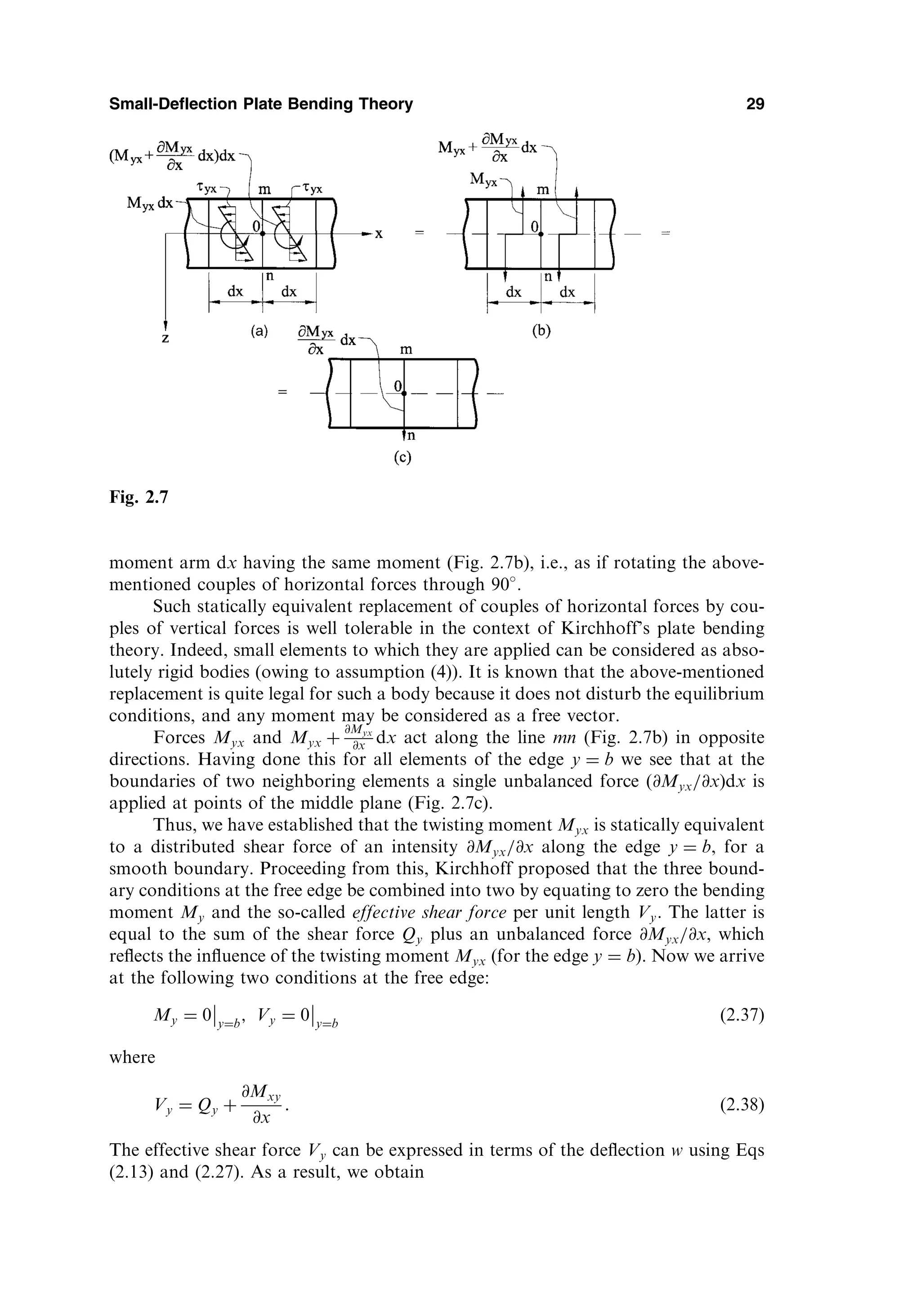
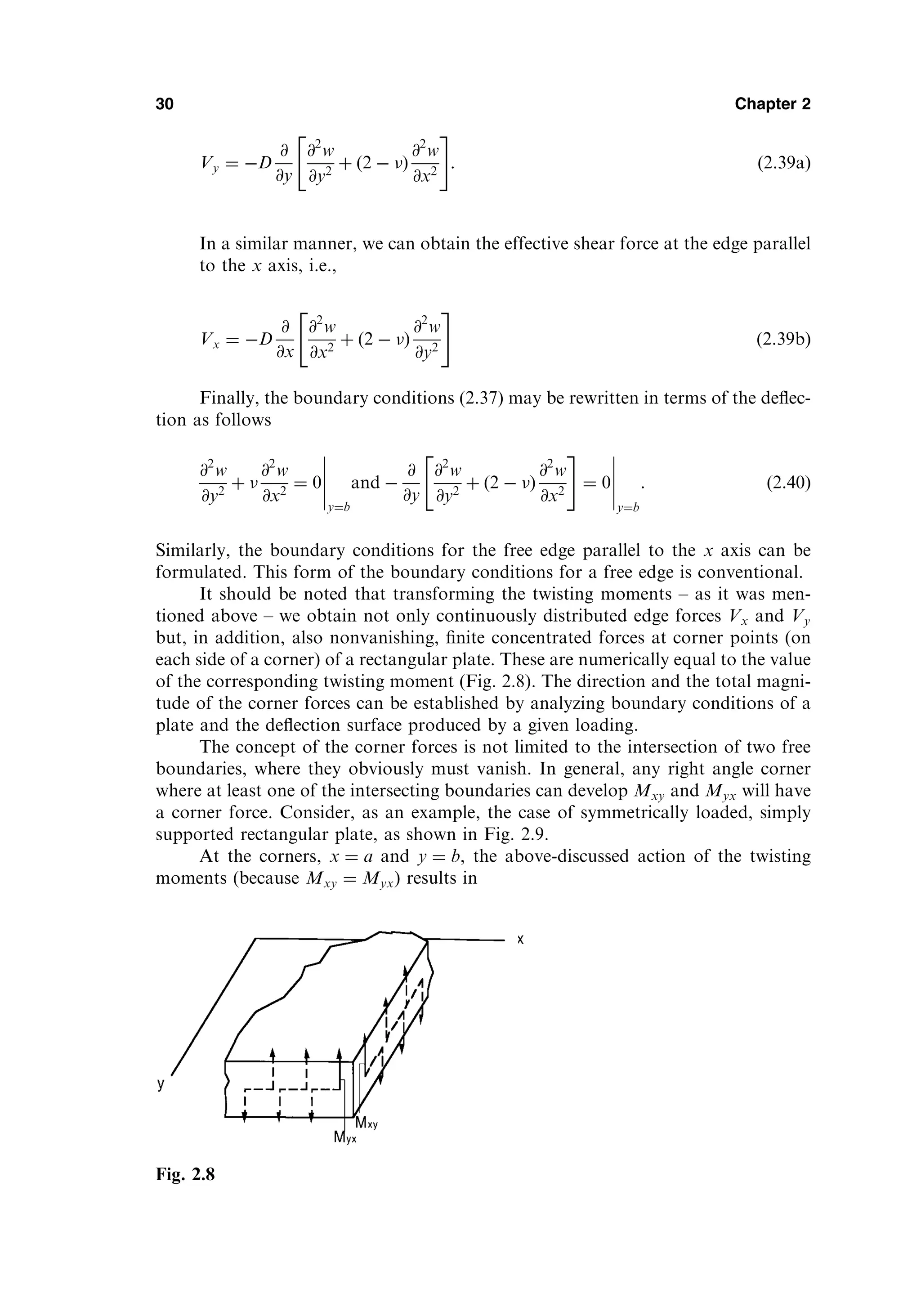
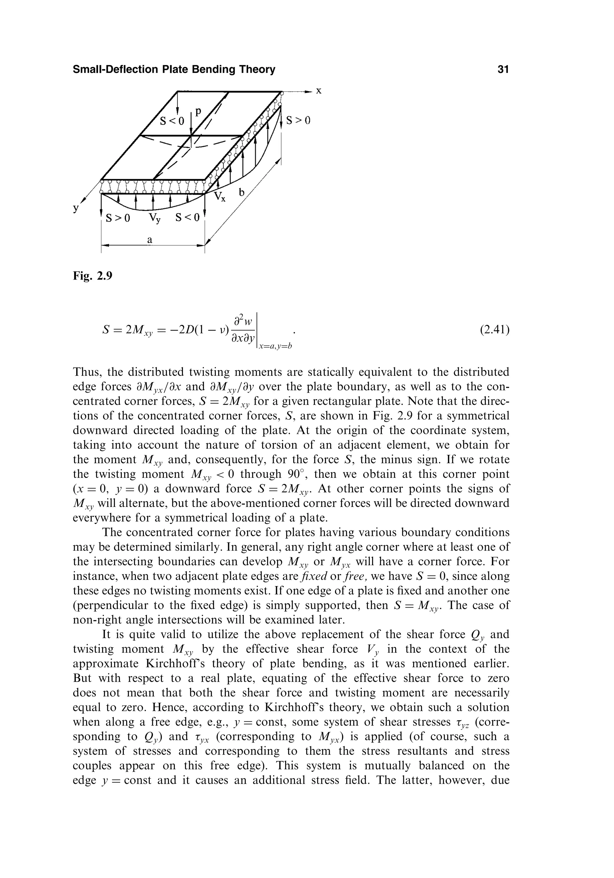
![to Saint-Venant’s principle, decays rapidly as we move away from this edge into
the interior of the plate. The above-mentioned additional stress field cannot be
determined by using the governing differential equation (2.24). Corrections can be
obtained using the plate bending equations with regard to the shear strains xz
and yz and will be discussed in Sec. 7.3. These corrections, as a rule, are neg-
ligible for solid isotropic plates.
(4) Edge x ¼ 0 supported by a beam
The boundary conditions of the type (2.33), (2.35), and (2.37) are called homogeneous
boundary conditions. Nonhomogeneous boundary conditions are commonly used in
many important engineering structures – for example, when a plate is supported by
an edge beam.
Assume that the cross section of the edge beam is symmetrical with respect to
the middle surface of the plate and the edge beam has flexural and torsional rigid-
ities. Since the edge beam and the plate are built monotonically (Fig. 2.10), they must
have the same displacements and slopes.
wb ¼ w x¼0
and #b ¼ # x¼0
or
@w
@x
b
¼
@w
@x x¼0
; ð2:42Þ
where the subscript b refers to the edge beam, and quantities relating to the plate
have no subscripts.
Consider an element dy of the edge beam as a free body, as shown in Fig. 2.10.
Equilibrium conditions of this element result in the following equations:
X
Fz ¼ 0: Qb Vxdy þ Qb þ
dQb
dy
dy ¼ 0
X
My ¼ 0: þ T þ Mxdy T þ
dT
dy
dy
¼ 0 or
Vx ¼
dQb
dy
ð0; yÞ; Mx ¼
dT
dy
ð0; yÞ ðaÞ
where T is the twisting moment in the beam.
As it follows from the beam theory [5]
32 Chapter 2
Fig. 2.10](https://image.slidesharecdn.com/438696-250518120012-4586dedb/75/Thin-Plates-And-Shells-Theory-Analysis-And-Applications-1st-Theodor-Krauthammer-41-2048.jpg)
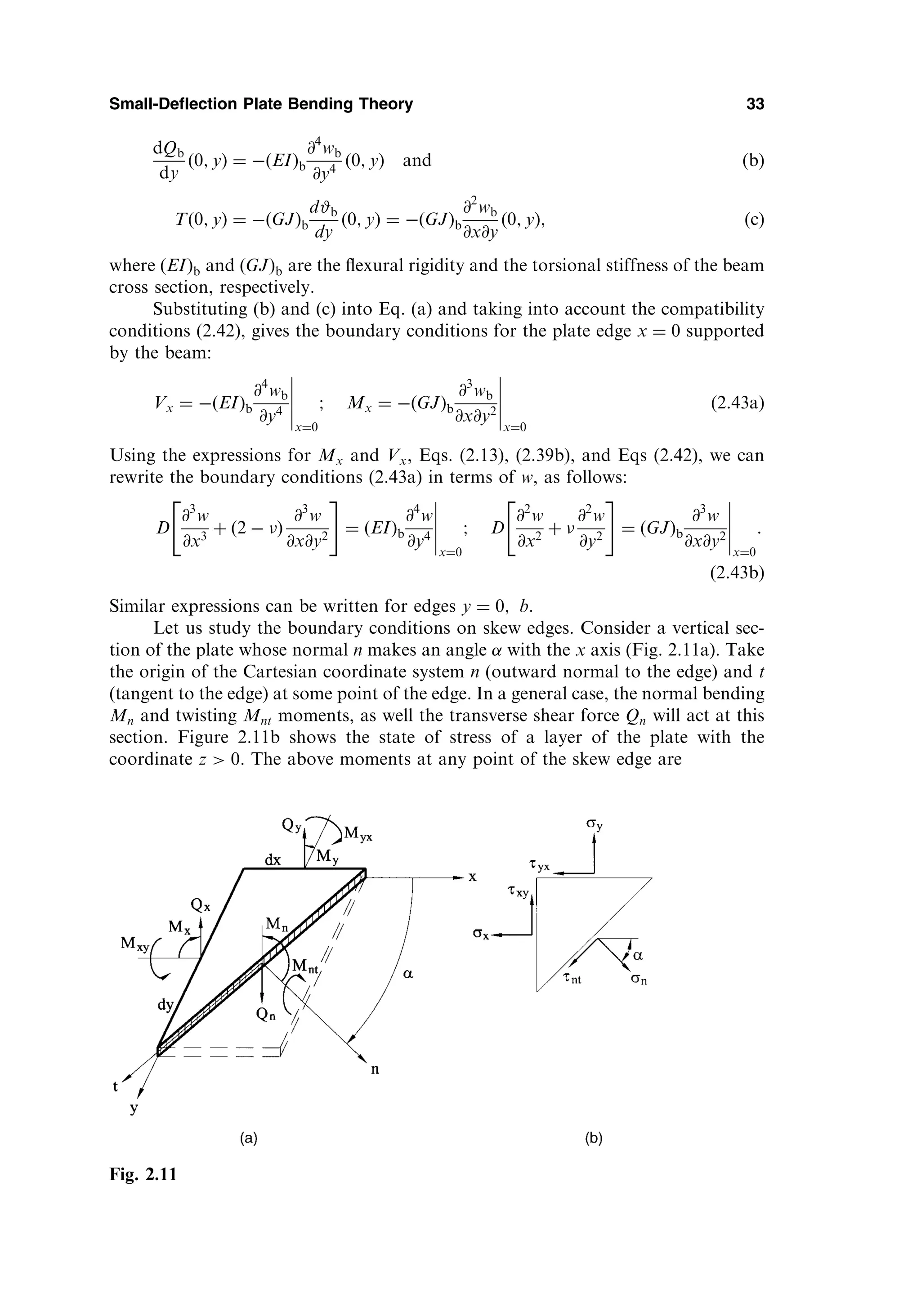
![Mn ¼
ð
h=2
h=2
nzdz; Mnt ¼
ð
h=2
h=2
ntzdz: ð2:44Þ
The relationship between the stress components shown in Fig. 2.11b is given by [6,7]
n ¼ x cos2
þ y sin2
þ 2xy cos sin ;
nt ¼ xy cos 2 ðx yÞ sin cos :
Substituting the above into Eqs (2.44), integrating over the plate thickness and
taking into account Eqs (2.11), one obtains the following relationships
Mn ¼ Mx cos2
þ My sin2
þ Mxy sin 2 ;
Mnt ¼ Mxy cos 2 ðMx MyÞ sin cos :
ð2:45Þ
The shear force Qn acting at a section of the edge having a normal n can be evaluated
from condition of equilibrium of the plate element shown in Fig. 2.11a, as follows:
Qnds Qxdy Qydx ¼ 0; from which
Qn ¼ Qx cos þ Qy sin :
ð2:46Þ
The effective shear force at a point of the skew edge can be determined similarly to
(2.38), i.e.,
Vn ¼ Qn þ
@Mnt
@t
; ð2:47Þ
where @=@t denotes a differentiation with respect to the tangent of the skew edge.
The boundary conditions discussed above for rectilinear edge can be general-
ized to some curvilinear edge. Let n and t be the outward normal making the angle
with the x axis and tangent to the curvilinear edge at a point of interest (Fig. 2.12).
Then the prescribed boundary conditions (2.33), (2.35), and (2.37), taking into
account (2.47), can be rewritten at an arbitrary point of the above curvilinear
edge, as follows:
34 Chapter 2
Fig. 2.12](https://image.slidesharecdn.com/438696-250518120012-4586dedb/75/Thin-Plates-And-Shells-Theory-Analysis-And-Applications-1st-Theodor-Krauthammer-43-2048.jpg)
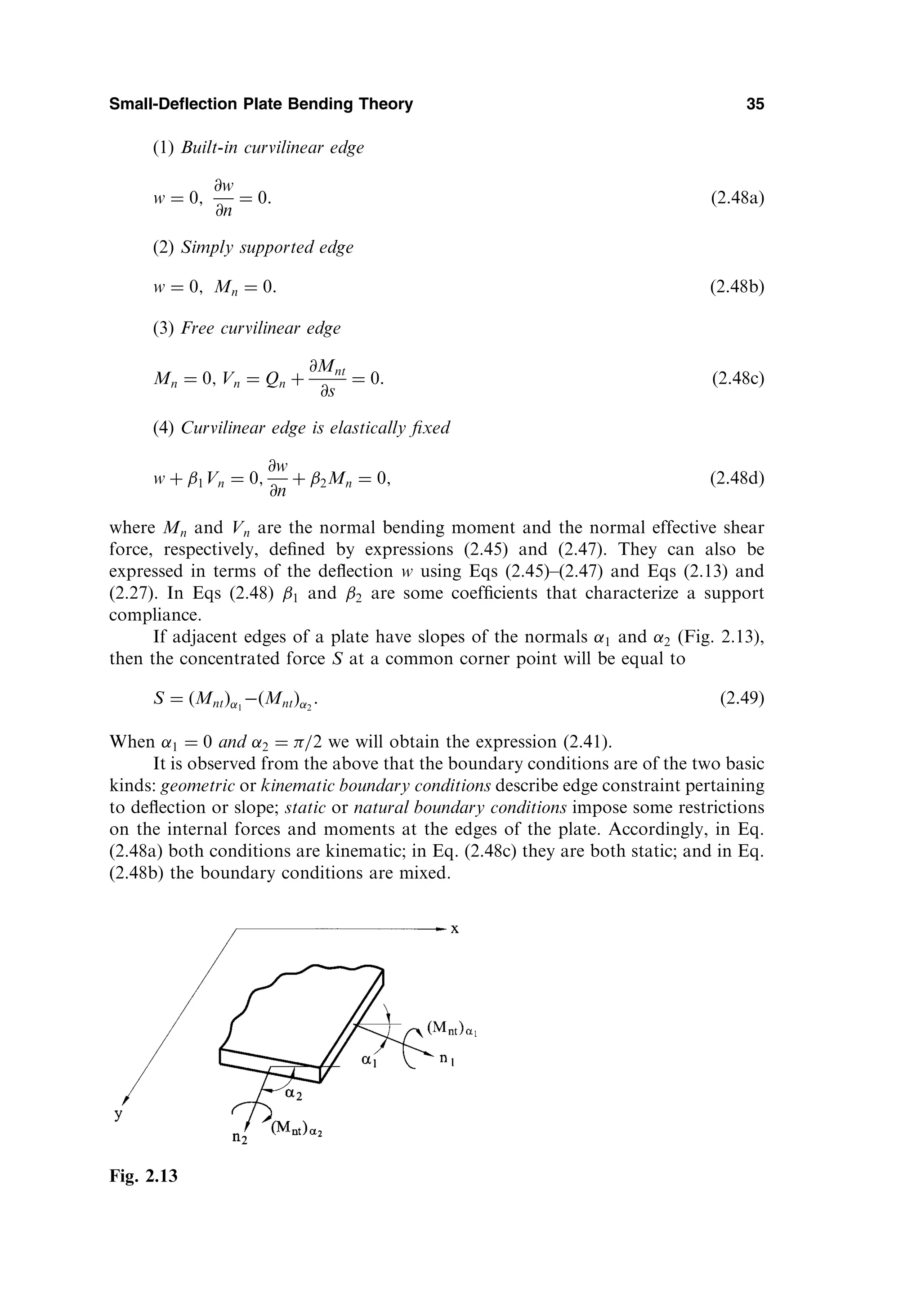
![2.6 VARIATIONAL FORMULATION OF PLATE BENDING PROBLEMS
It is known from the theory of elasticity that governing equations for stresses,
strains, and displacements can be represented in the differential form. However,
this is not a unique possible formulation of the problem for finding the stress–strain
field of an elastic body. The problem of determining stresses, strains, and displace-
ments can be reduced to some definite integral of one or another type of these
functions called functionals. Then, the functions themselves (stresses, strains, and
displacements) reflecting a real state of a body can be found from conditions of
extremum for this functional. The mathematical techniques of such an approach is
studied in the division of mathematics called the calculus of variation. Therefore,
some postulates and statements that formulate properties of these functionals in the
theory of elasticity are referred to as variational principles. The latter represent some
basic theorems expressed in the form of integral equalities connecting stresses,
strains, and displacements throughout the volume of a body and based on the
properties of the work done by external and internal forces. A variety of powerful
and efficient approximate methods for analysis of various linear and nonlinear pro-
blems of solid mechanics are based on the variational principles. Some of these
methods will be described further in Chapter 6.
2.6.1 Strain energy of plates
A functional is a scalar quantity depending on some function or several functions, as
from independent variables. The functional can be treated as a function of an infinite
number of independent variables. The subject matter of the calculus of variation is
searching of unknown functions fiðx; y; zÞ that give a maximum (minimum) or sta-
tionary value of a functional. For example,
¼
ð ð
V
ð
F f1ðx; y; zÞ; f2ðx; y; zÞ; . . . ; fnðx; y; zÞ; f 0
1 ðx; y; zÞ; . . . ;
f 0
n ðx; y; zÞ; x; y; z
dV:
The above-mentioned functions for which the functional is maximum (minimum) or
stationary are referred to as extremals of the given functional [8–11].
Let us consider a functional expressing the total potential energy of a deformed
elastic body and the loads acting on it. The total potential energy, , consists of the
strain energy of deformation (the potential of internal forces), U, and the potential
energy of external forces (the potential of external forces), , i.e.,
¼ U þ : ð2:50Þ
By convention, let us assume that the potential energy at the initial, undeformed
state, 0, is zero. Hence, the total energy presents a variation of the energy of
internal and external forces in the transition from initial to deformed states. The
potential energy of a body is measured by the work done by external and internal
forces when this body returns from its final to an initial position (where it was
mentioned above, 0 ¼ 0).
Our study is mainly limited to linearly elastic bodies that dissipate no energy
and have only one equilibrium configuration. We also require that loads keep the
36 Chapter 2](https://image.slidesharecdn.com/438696-250518120012-4586dedb/75/Thin-Plates-And-Shells-Theory-Analysis-And-Applications-1st-Theodor-Krauthammer-45-2048.jpg)
![same orientation in space as they move. Such loads are called conservative. A
mechanical system is called conservative if zero net work is done in carrying the
system around any closed path: that is, in arbitrary changing a configuration and
then restoring it. An extension of this study to nonlinear, or nonconservative, pro-
blems is possible.
First, let us set up an expression for the potential of the internal forces (strain
energy of deformation). This potential is equal to the negative work of the internal
forces, i.e., U ¼ Wi. Since the work done by the internal forces, Wi, is always
negative (because displacements always occur in the opposite direction with respect
to applied internal forces), the strain energy is positive.
The strain energy stored in an elastic body for a general state of stress is given
by [6,7]
U ¼
1
2
ð ð ð
V
xx þ yy þ zz þ xyxy þ xzxz þ yzyz
dV: ð2:51Þ
The integration extends over the entire body volume V. Based upon the assumptions
of Kirchhoff’s small-deflection plate bending theory, the stress components z; xz;
and yz may be omitted. Thus, introducing the generalized Hooke’s law, the above
expression reduces to the following form, involving only stresses and elastic con-
stants,
U ¼
ð ð ð
V
1
2E
2
x þ 2
y 2xy
þ
1 þ
E
2
xy
dV: ð2:52Þ
Substituting for the stress components from Eq. (2.10) into Eq. (2.52) and integrat-
ing it over the thickness of the plate, we obtain
U ¼
1
2
ð ð
A
D
@2
w
@x2
!2
þ
@2
w
@y2
!2
þ 2
@2
w
@x2
@2
w
@y2
þ 2ð1 Þ
@2
w
@x@y
!2
2
4
3
5dA ð2:53Þ
or alternatively
U ¼
1
2
ð ð
A
D
@2
w
@x2
þ
@2
w
@y2
!2
2ð1 Þ
@2
w
@x2
@2
w
@y2
@2
w
@x@y
!2
2
4
3
5
8
:
9
=
;
dA ð2:54Þ
where A is the area of the plate middle surface.
We can also rewrite the expression (2.53) for the strain energy in terms of the
bending and twisting moments, and the corresponding curvatures by the use of Eqs
(2.13). As a result, for plates of a constant thickness the strain energy is
U ¼
1
2
ð ð
A
Mxx þ Myy þ 2Mxyxy
dA: ð2:55Þ
Small-Deflection Plate Bending Theory 37](https://image.slidesharecdn.com/438696-250518120012-4586dedb/75/Thin-Plates-And-Shells-Theory-Analysis-And-Applications-1st-Theodor-Krauthammer-46-2048.jpg)
![We observe from Eqs (2.53) and (2.54) that the strain energy is a nonlinear (quad-
ratic) function of deformations. Hence, the principle of superposition is therefore not
valid for the strain energy.
The expressions (2.53) and (2.54) are valid for plates of constant and variable
thickness. It should be noted that the following integral
ð ð
A
@2
w
@x2
@2
w
@y2
@2
w
@x@y
!2
2
4
3
5dA ð2:56Þ
entering in Eq (2.54) is equal to zero for fixed supports and for simply supported
edges of plates, whose contour is traced by straight lines. This statement can be easily
proven by transforming the integral (2.56) over the plate surface into the line integral
over the plate boundary [3].
The potential of external forces, , is defined as the work done by external
forces through the corresponding displacements, assuming that these forces remain
unchanged during the deformation. Further, when a positive displacement occurs,
decreases, so the potential of the external forces is always negative and may be
evaluated as the product of these forces and the corresponding final displacement
components. Determine the potential, p, of the distributed load pðx; yÞ and con-
centrated Pi and Mj forces and moments applied to the middle surface of the plate as
follows:
p ¼
ð ð
A
pðx; yÞwdA þ
X
i
Piwi þ
X
j
Mj#j
2
4
3
5; ð2:57Þ
where wi and #j are the deflection and the slope of the normal at the point of
application of the ith force and jth moment in the plane of the action of this moment,
respectively.
In the expression (2.57) the potential of edge loads, , is not included. These
loads have potentials only if compatible boundary displacements are permitted. In
such cases, the potentials of the edge moments mn; mt and the transverse edge forces
Vn can be expressed as
¼
þ
Vnw þ mn
@w
@n
þ mnt
@w
@t
ds; ð2:58Þ
where @w=@n and @w=@t are the derivatives of w with respect to the outward normal
and the tangent directions, respectively, along the plate boundary to the boundary .
The total potential of the external loads applied to the plate surface and to its
boundary is
¼ p þ ; ð2:59Þ
where p and are given by the expressions (2.57) and (2.58).
Using expressions (2.50), (2.54), (2.57) and (2.58), we can write the total poten-
tial energy of the plate in bending in the Cartesian coordinates as follows
38 Chapter 2](https://image.slidesharecdn.com/438696-250518120012-4586dedb/75/Thin-Plates-And-Shells-Theory-Analysis-And-Applications-1st-Theodor-Krauthammer-47-2048.jpg)
![they are imagined to take place (i.e., hypothetical), with the actual loads acting at
their fixed values. The admissible virtual displacement produces an admissible
configuration of the body. It follows from the above that virtual displacements
cannot affect the equilibrium of the given system, when the full loads have been
applied. Neither external loads nor internal forces and moments are altered by a
virtual displacement [8–12, 14].
Now we can introduce the general variational principles of solid mechanics.
(a) The Principle of Conservation of Energy
This principle states that the strain energy stored in an elastic body is equal to the work
done by the applied external loads during the loading process, if we assume that there
are no thermal or inertial effects.
(b) The Principle of Virtual Work
The work done by actual forces through a virtual displacement of the actual con-
figuration is called virtual work. It is assumed that during the virtual displacements
all forces are held constant. The virtual work is designated by W.
The principle of virtual work is formulated as follows:
An elastic body is in equilibrium if and only if the total virtual work done by external
and internal forces is zero for any admissible virtual displacements, i.e.,
W ¼ Wi þ We ¼ 0 (2.62)
where Wi and We are the virtual works done by internal and external forces,
respectively. As mentioned earlier, Wi is negative. This principle was first pro-
posed by J. Bernoulli in 1771. It can be interpreted as follows: if a body is in
equilibrium then its resultant force and resultant couple are both zero; so, they
produce no work.
(c) The Principle of Minimum Potential Energy
The principle of minimum potential energy may be looked upon as a specialization
of the principle of virtual work (2.62). Indeed, the potential energy of the internal
forces is equal to the negative work of the internal forces, i.e., U ¼ Wi. On the
other hand, We ¼ . Therefore, we can write the equality (2.62), as follows:
W ¼ U ¼ 0; ð2:63Þ
where U þ ¼ ðU þ Þ ¼ (because can be treated as a differential of a
function) and is the variation in the total potential energy due to introducing
compatible virtual displacements and is given by Eq. (2.60) or Eq. (2.61). Finally, the
equality (2.63) can be written as
¼ 0: ð2:64Þ
This equality expresses the principle of minimum potential energy proposed by
Lagrange.
From calculus, an equality df ¼ 0 means that the function f has an extremum
(or a value corresponding to a point of inflection). It can be shown [9,10] that a
variation of the total potential energy during any admissible virtual displacement
(variation of the displacement) is positive for any stable configuration of equili-
40 Chapter 2](https://image.slidesharecdn.com/438696-250518120012-4586dedb/75/Thin-Plates-And-Shells-Theory-Analysis-And-Applications-1st-Theodor-Krauthammer-49-2048.jpg)
![brium. Hence, in this case, the total potential energy of a given system has a mini-
mum. From the uniqueness theorem [6,7], the problem of the theory of elasticity,
based on assumptions of small displacements and deformations defines only one
equilibrium configuration, and this configuration of equilibrium is stable. Thus, if
the small-deflection theory of an elastic body is being studied, then the potential
energy is a minimum in an equilibrium state. So, the principle of minimum potential
energy, proposed by Lagrange, can be formulated, as follows:
Among all admissible configurations of an elastic body, the actual configuration (that
satisfies static equilibrium conditions) makes the total potential energy, , stationary
with respect to all small admissible virtual displacements. For stable equilibrium, is a
minimum.
Notice that the above principle applies to a conservative system only.
It can be shown that the governing differential equation (2.24) and the bound-
ary conditions (2.48) can be deduced from Lagrange’s variational principle (2.64)
[3,8–12]. However, the key importance of the variational principles discussed above
is that they can be used to obtain approximate solutions of complicated problems of
solid mechanics, in particular, plate-shell bending problems. These are obtained
while avoiding mathematical difficulties associated with integration of differential
equations in partial derivatives. The corresponding methods, called variational meth-
ods and based on the above-mentioned principles, are discussed further in Chapter 6.
More complete information on the variational principles and their application in
mechanics is available in the literature [8–12].
PROBLEMS
2.1 Verify the result given by Eq. (2.18).
2.2 Derive the governing differential equation for deflections of a plate subjected to a
distributed moment load mxðx; yÞ and myðx; yÞ applied to the middle surface.
2.3 Show that at the corner of a polygonal simply supported plate, Mxy ¼ 0 unless the
corner is 90 .
2.4 If a lateral deflection w is a known function of x and y, what are the maximum slope
@w=@n and the direction of axis n with respect to the x axis in terms of @w=@x and
@w=@y?
2.5 Show that the sum of bending curvatures in any two mutually perpendicular directions,
n and t, at any point of the middle surface, is a constant, i.e.,
x þ y ¼ n þ t ¼ const:
2.6 Verify the expression given by Eq. (2.61).
2.7 Derive the expressions for the boundary quantities Mn; Mnt; and Vn in terms of the
deflection w at a regular (smooth) point of the curvilinear contour of the plate using:
(a) the local coordinates n and t where the coordinate n coincides with the direction of
the outward normal and t – with the tangent direction to the boundary; (b) the intrinsic
coordinates n and s, where s, is the arc length over the boundary.
Hint: use the following relations for part (b)
@n
@s
¼
1
t;
@t
@s
¼
1
n
where n and t are the unit vectors of the intrinsic coordinate system directed along the
outward normal and tangent to the boundary, respectively.
Small-Deflection Plate Bending Theory 41](https://image.slidesharecdn.com/438696-250518120012-4586dedb/75/Thin-Plates-And-Shells-Theory-Analysis-And-Applications-1st-Theodor-Krauthammer-50-2048.jpg)