29-mal heruntergeladen


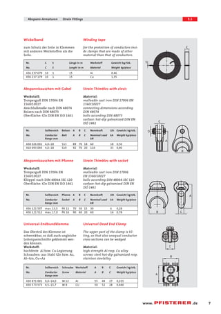
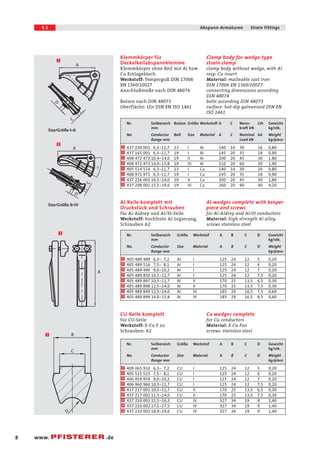
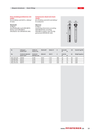
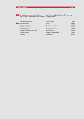

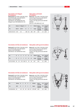
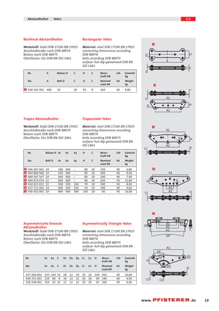
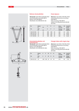
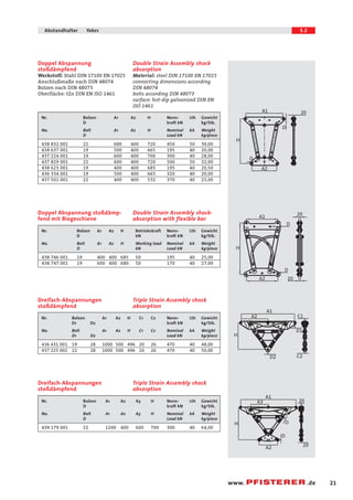
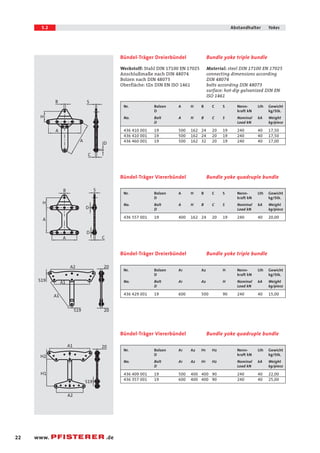


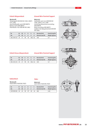
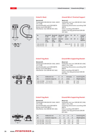
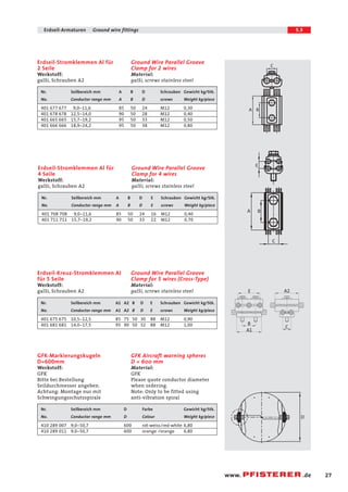

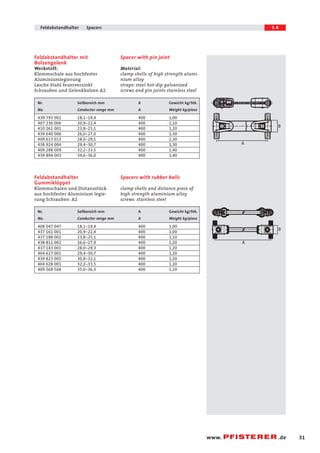

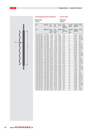

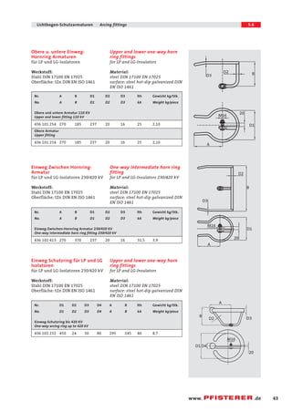
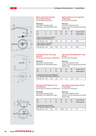
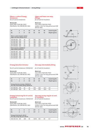
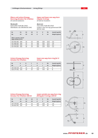
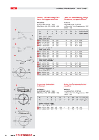
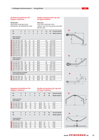
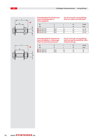


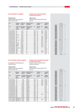
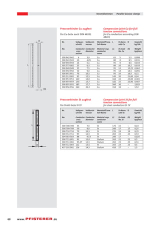


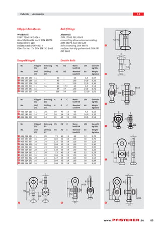
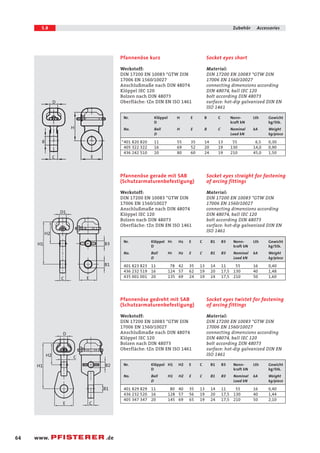
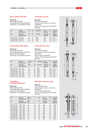
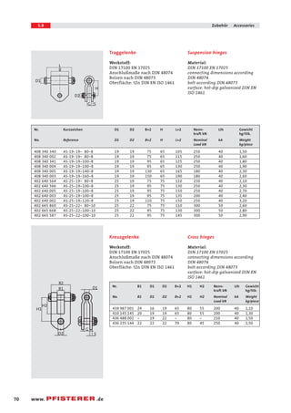
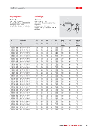
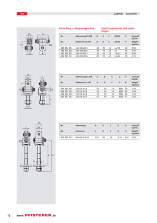
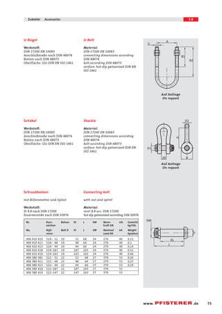
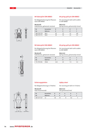


Das Dokument enthält technische Informationen und Spezifikationen über Freileitungsarmaturen für Mittel- und Hochspannungsnetze, einschließlich verschiedener Arten von Abspann- und Zugklemmen sowie deren Materialien und Maße. Es listet Produkte von Thorne & Derrick UK auf, die zur Installation und Wartung von Stromnetzen verwendet werden. Technische Parameter wie Nennlast, Gewicht und Materialeigenschaften sind ebenfalls enthalten.


